
IAN 331996_1907
INVERTER WELDER
INVERTNÁ ZVÁRAČKA
INVERTERSKI VARILNI APARAT
INVERTER-SCHWEISSGERÄT
INVERTNÍ SVÁREČKA
INVERTERES HEGESZTŐKÉSZÜLÉK
Operation and Safety Notes
Translation of the original instructions
Návod na obsluhu a bezpečnostné upozornenia
Originálny návod na obsluhu
Navodila za upravljanje in varnostna opozorila
Prevod originalnega navodila za uporabo
Bedienungs- und Sicherheitshinweise
Originalbetriebsanleitung
Návod k obsluze a bezpečnostní pokyny
Originální návod k obsluze
Kezelési és biztonsági hivatkozások
Az eredeti használati utasítás fordítása
GB
SK
SI
DE
CZ
HU
AT
CH
INVERTER WELDER PISG 120 A2
SK
SI
CZ
HU
331996_Inverter_Schweissgeraet_PISG_120_A2_cover_LB4.indd 3 05.12.19 15:44

GB
Before reading, unfold the page containing the illustrations and familiarise yourself with all
functions of the device.
HU
Olvasás előtt hajtsa ki az ábrát tartalmazó oldalt, és ezután ismerje meg a készülék
mindegyik funkcióját.
SI
Pred branjem odprite stran s slikami in se nato seznanite z vsemi funkcijami naprave.
CZ
Než začnete číst tento návod k obsluze, rozložte stránku s obrázky a seznamte se se všemi
funkcemi zařízení.
SK
Prv než začnete čítať tento návod, rozložte si stranu s obrázkami a potom sa oboznámte so
všetkými funkciami zariadenia.
DE AT CH
Klappen Sie vor dem Lesen die beiden Seiten mit den Abbildungen aus und machen Sie sich
anschließend mit allen Funktionen des Gerätes vertraut.
GB Operation and Safety Notes Page 5
HU Kezelési és biztonsági hivatkozások Oldal 23
SI Navodila za upravljanje in varnostna opozorila Stran 43
CZ Návod k obsluze a bezpečnostní pokyny Strana 61
SK Návod na obsluhu a bezpečnostné upozornenia Strana 79
DE / AT / CH Montage-, Bedienungs- und Sicherheitshinweise Seite 97
331996_Inverter_Schweissgeraet_PISG_120_A2_cover_LB4.indd 4 05.12.19 15:44

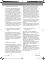
A
C1
C3
C2
C4
B
–
(schwarz)
+
(rot)
1
4
10
9
5
8 7
7
11
1 2
2
3
331996_Inverter_Schweissgeraet_PISG_120_A2_cover_LB4.indd 5 05.12.19 15:44

6 7 11
8
331996_Inverter_Schweissgeraet_PISG_120_A2_cover_LB4.indd 8 05.12.19 15:44

5GB
Table of contents
List of pictograms used .........................................................................Page 6
Introduction ..............................................................................................Page 7
Intended use ................................................................................................ Page 7
Package contents .........................................................................................Page 7
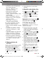
Parts description ..........................................................................................Page 7
Technical specifications .................................................................................Page 7
Safety instructions ..................................................................................Page 8
Potential hazards during electric arc welding ................................................... Page 10
Welding mask-specific safety instructions .........................................................Page 12
Environment with increased electrical hazard...................................................Page 13
Welding in tight spaces ................................................................................Page 14
Total of open circuit voltages .........................................................................Page 14
Using shoulder straps ...................................................................................Page 14
Protective clothing ........................................................................................Page 15
EMC Device Classification ............................................................................Page 15
Before use .................................................................................................Page 16
Fit welding mask ....................................................................................Page 16
Using the device ...................................................................................... Page 16
Welding .....................................................................................................Page 18
Maintenance and cleaning ................................................................... Page 18
Information about recycling and disposal ....................................... Page 19
EU Declaration of Conformity ..............................................................Page 19
Warranty and service information ....................................................Page 20
Warranty conditions ..................................................................................... Page 20
Warranty period and statutory claims for defects .............................................Page 20
Extent of warranty ........................................................................................Page 20
Processing of warranty claims ........................................................................Page 21
Service .......................................................................................................Page 21
331996_Inverter_Schweissgeraet_PISG_120_A2_content_LB4.indb 5 05.12.19 15:41

6 GB
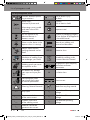
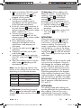
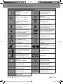
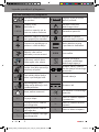
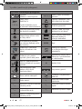
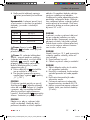
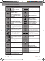
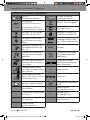
List of pictograms used
List of pictograms used
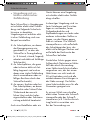
Caution! Read the operat-
ing instructions!
Risk of serious injury
or death.
1~50 Hz
Power input;
Number of phases and
Alternating current symbol
and rated value of the
frequency.
Caution!
Risk of electric shock!
Important note!
Do not dispose of any
electrical devices in
domestic waste!
Dispose of packaging properly.
Do not dispose of the appliance
in household waste!
Never use the device in the
open or when it’s raining!
Manual arc welding with
encased rod electrodes.
Electric shock from the
welding electrode can be
fatal!
IP21S Protection class.
Inhalation of welding fumes
can endanger your health.
Suitable for welding under
increased electrical hazard.
Welding sparks can cause
an explosion or fire.
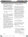
Single-phase static frequency
converter-transformer-
commutator.
Arc beams can damage
your eyes and injure your
skin.
H Insulation class.
Electromagnetic fields
can disrupt the function
of cardiac pacemakers.
Direct current.
Warning: Potential hazards!
Made from recycling material.
X % Duty cycle. U
0
Rated value of the open circuit
voltage
I
1 max
Greatest rated value
of the mains current
U
1
Rated value of the mains
voltage
I
2 max
Greatest rated value
of the welding current
U
2
Standardised operating
voltage
I
1 eff
Effective value of the
greatest mains current
331996_Inverter_Schweissgeraet_PISG_120_A2_content_LB4.indb 6 05.12.19 15:41

7GB
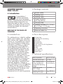
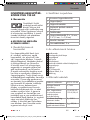
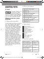
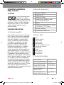
INVERTER WELDER
PISG 120 A2
Introduction
Congratulations!
You have purchased
one of our high-quality
products. Please familiarise yourself with
the product before setup or first use.
Please also read the safety instructions
carefully. This product must be set up or
used only by people who have been
trained to do so.
KEEP OUT OF THE REACH OF
CHILDREN!
Intended use
This welding device is ideal for welding
metals such as carbon steel, steel alloy,
other stainless steel, copper, aluminium,
titanium, etc. The product has a control
lamp, a heat protection display and a
cooling fan. In addition, it is fitted with
a carrying strap so that the product
can be lifted and moved safely. If it is
not handled properly the product can
be dangerous for individuals, animals
and property. Use the product only
as described and only for the specific
applications as stated. Keep these
instructions in a safe place. Ensure you
hand over all documentation when
passing the product on to anyone else.
Any use that differs to the intended
use as stated above is prohibited and
potentially dangerous. Damage or
injury caused by misuse or disregarding
the above warning is not covered by
the warranty or any liability on the part
of the manufacturer. The device is not
intended for commercial use.
Commercial use will void the guarantee.
Package contents
1 Inverter welder
1 Welding mask
2 Welding cables
1 Combi wire brush
with slag hammer
1 Carrying strap
5 Welding electrodes (2 x 1.6 mm;
2 x 2.0 mm; 1 x 2.5 mm)
1 Operating instructions
1 Extension cable 2 m
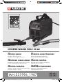
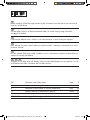
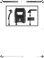
Parts description
1
Carrying strap
2
Control lamp for overheating
3
Rotary knob
4
Earth terminal
5
Electrode holder
6
Combi wire brush with slag hammer
7
Welding mask
8
Handle
9
ON/OFF switch
10
Power cable 2 m
11
Protective glass
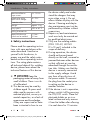
Technical specifications
Mains connection: 230 V~ 50 Hz
Nominal power input: 3.7 kW
Max. welding current
and the appropriate
standardised operating
voltage:
10 A/20.4 V -
120 A/24.8 V
Rated value of the
mains voltage:
U
1
:230V
Greatest rated value
of the mains current:
I
1max
: 25.2 A
Introduction
331996_Inverter_Schweissgeraet_PISG_120_A2_content_LB4.indb 7 05.12.19 15:41

8 GB
Maximum effective
input current:
I
1eff
: 13.8 A
Rated value of the
open circuit voltage:
U
0
: 70 V
Protection class: IP21S
Weight: approx. 3 kg
Duty cycle X: 30% at 40 °C
Falling characteristic
Material thicknesses
which can be welded:
1.5 mm -
3.0 mm
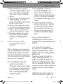
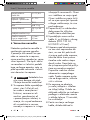
Safety instructions
Please read the operating instruc-
tions with care and observe the
notes described. Familiarise
yourself with the device, its
proper use and the safety notes
based on these operating instruc-
tions. The rating plate contains
all technical data of this welding
device; please learn about the
technical features of this device.
Keep the
packaging material away from
small children. There is a risk
of suffocation!
This device may be used by
children aged 16 years and
older, and by persons with
reduced physical, sensory or
mental capacities, or a lack of
experience and knowledge,
if they are supervised or have
been instructed in how to use
the device safely and under-
stand the dangers that may
arise when using it. Do not
allow children to play with the
device. Cleaning and day-to-
day maintenance must not be
performed by children without
supervision.
Repairs or/and maintenance
work must only be carried out
by qualified electricians.
Only use the welding cables
(PISG 120 A2, H01N2-
D1x10mm
2
) included in the
scope of delivery.
During operation, the device
should not be positioned
directly on the wall, covered or
jammed between other devices
so that sufficient air can be
absorbed through the ventila-
tion slats. Makes sure that the
device is correctly connected
to the supply voltage. Avoid
any form of tensile stress of
the power cable. Disconnect
the plug from the socket prior
to setting up the device in
another location.
If the device is not in operation,
always switch it off by pressing
the ON/OFF switch. Place the
electrode holder on an insu-
lated surface and only remove
it from the holder after allowing
it to cool down for 15 minutes.
Introduction / Safety instructions
331996_Inverter_Schweissgeraet_PISG_120_A2_content_LB4.indb 8 05.12.19 15:41

9GB
Pay attention to the condition
of the welding cable, electrode
holder and the earth terminal.
Wear and tear of the insulation
and the live parts can lead to
hazards and reduce the quality
of the welding work.
Arc welding creates sparks,
molten metal parts and
smoke. Therefore ensure that:
All flammable substances and/
or materials are removed from
the work station and its imme-
diate surrounding.
Ensure the work station is
ventilated.
Do not weld on containers,
vessels or tubes that contain
or contained flammable liquids
or gases.
Avoid any
form of direct contact with the
welding current circuit. The
open circuit voltage between
the electrode holder and earth
terminal can be dangerous,
there is a risk of electric shock.
Do not store or use the device
in a damp or wet environment
or in the rain. Protection rating
IP21S is applicable in this case.
Protect your eyes using the
appropriate protective glasses
(DIN level 9-10), which are
fastened to the supplied weld-
ing mask. Wear gloves and
dry protective clothing that are
free of oil and grease to pro-
tect the skin from exposure to
ultraviolet radiation of the arc.
Do not use
the welding power source to
defrost pipes.
Please note:
The light radiation emitted by
the electric arc can damage
eyes and cause burns to
the skin.
Arc welding creates sparks
and drops of melted metal.
The welded workpiece starts
to glow and remains hot
for a relatively long period.
Therefore, do not touch the
workpiece with bare hands.
Arc welding can cause
vapours to be release that
may be hazardous to health.
Be careful not to inhale these
vapours.
Protect yourself from the
harmful effects of the electric
arc and keep people that are
not involved in the work away
from the arc maintaining a
distance of at least 2 m.
ATTENTION!
During the operation of the
welding device, other consum-
ers may experience problems
Safety instructions
331996_Inverter_Schweissgeraet_PISG_120_A2_content_LB4.indb 9 05.12.19 15:41

10 GB
with the voltage supply
depending on the network
conditions at the connection
point. In case of doubt, please
contact your energy supply
company.
During the operation of the
welding device, other devices
may malfunction, e.g. hearing
aids, cardiac pacemakers, etc.
Potential hazards during
electric arc welding
There are a series of potential
hazards that can occur during
electric arc welding. It is there-
fore particularly important for the
welder to observe the following
rules to avoid endangering him/
herself and others and to prevent
damage to people and the
device.
Work on the voltage side,
e.g. on cables, plugs, sockets
etc., may only be carried
out by qualified electricians
according to national and
local regulations.
In the event of accidents,
disconnect the welding
device from the mains voltage
immediately.
If electrical contact voltages
occur, switch off the device
immediately and have it
checked by a qualified
electrician.
Always ensure good electrical
contacts on the welding
current side.
Always wear insulating gloves
on both hands during welding
work. These provide protection
from electrical shocks (no-load
voltage of the welding current
circuit), harmful radiations
(heat and UV radiation)
and incandescent metal and
splashes of slag.
Wear sturdy, insulating shoes.
The shoes should also insulate
when exposed to moisture.
Loafers are not suitable as
falling incandescent metal
droplets can cause burns.
Wear suitable protective cloth-
ing, no synthetic garments.
Do not look into the electric
arc without eye protection;
only use a welding mask with
the prescribed protective glass
as per DIN. In addition to light
and heat radiation, which
can dazzle or cause burns,
the electric arc also emits UV
radiation. Without suitable
protection the invisible ultravi-
olet radiation can cause very
painful conjunctivitis which
is not apparent until several
hours later. Furthermore, UV
Safety instructions
331996_Inverter_Schweissgeraet_PISG_120_A2_content_LB4.indb 10 05.12.19 15:41

11GB
radiation can cause burns with
sunburn-like effects on unpro-
tected parts of the body.
Any persons in the vicinity
of the electric arc or helpers
must also be informed of the
dangers and be equipped
with the necessary protective
equipment. If necessary, set up
protective walls.
Ensure an adequate supply
of fresh air whilst welding,
particularly in small spaces,
as it produces smoke and
harmful gases.
No welding work may be
carried out on containers that
have been used for storing
gases, fuels, mineral oils or
similar – even if they have
been empty for a long time
– as possible residues may
present a risk of explosion.
Special regulations apply in
rooms where there is a risk of
fire or explosion.
Welded joints that are subject
to heavy stress loads and are
required to comply with certain
safety requirements may only
be carried out by specially
trained and certified welders.
Examples of this are pressure
vessels, running rails, tow
bars, etc.
ATTENTION! Always connect
the earth terminal as close as
possible to the point of weld to
provide the shortest possible path
for the welding current from the
electrode to the earth terminal.
Never connect the earth terminal
to the housing of the welding
device! Never connect the earth
terminal to earthed parts far
away from the workpiece, e.g. a
water pipe in another corner of
the room. This could otherwise
damage the protective bonding
system of the room you are
welding.
Do not use the welding device
in the rain.
Do not use the welding device
in a moist environment.
Only place the welding device
on a level surface.
The output is rated at an
ambient temperature of 20°C.
The welding time can be
reduced at higher temperatures.
Risk of electric shock:
Electric shock from the
welding electrode can be
fatal. Do not weld in rain or
snow. Wear dry insulating
gloves. Do not touch the elec-
trodes with bare hands. Do not
wear wet or damaged gloves.
Safety instructions
331996_Inverter_Schweissgeraet_PISG_120_A2_content_LB4.indb 11 05.12.19 15:41

12 GB
Protect yourself from electric
shock with insulation against
the workpiece. Do not open
the device housing.
Danger from welding
fumes:
Inhalation of welding fumes
can endanger health.
Do not keep your head in the
fumes. Use the equipment in
open areas. Use extractors
to remove the fumes.
Danger from welding
sparks:
Welding sparks can cause
an explosion or fire. Keep
flammable substances away
from the welding location.
Do not weld next to flammable
substances. Welding sparks
can cause fires. Keep a fire
extinguisher close by and an
observer should be present to
be able to use it immediately.
Do not weld on drums or any
other closed containers.
Danger from arc beams:
Arc beams can damage your
eyes and injure your skin.
Wear a hat and safety goggles.
Wear hearing protection and
high, closed shirt collars.
Wear welding safety helmets
and make sure you use the
appropriate filter settings. Wear
complete body protection.
Danger from electro-
magnetic fields:
Welding current generates
electromagnetic fields.
Do not use if you have a
medical implant. Never wrap
the welding cable around your
body. Guide welding cables
together.
Welding mask-specific
safety instructions
With the help of a bright light
source (e.g. lighter) examine
the proper functioning of the
welding mask prior to starting
with any welding work.
Weld spatters can damage the
protective screen. Immediately
replace damaged or scratched
protective screens.
Immediately replace damaged
or highly contaminated or
splattered components.
The device must only be
operated by people over the
age of 16.
Safety instructions
331996_Inverter_Schweissgeraet_PISG_120_A2_content_LB4.indb 12 05.12.19 15:41

13GB
Please familiarise yourself
with the welding safety instruc-
tions. Also refer to the safety
instructions of your welding
device.
Always wear a welding mask
while welding. If it is not
used, you could sustain severe
lesions to the retina.
Always wear protective cloth-
ing during welding operations.
Never use the welding mask
without the protective screen.
Regularly replace the protec-
tive screen to ensure good
visibility and fatigue-proof
work.
Environment with
increased electrical
hazard
When welding in environments
with increased electrical hazard,
the following safety instructions
must be observed. Environments
with increased electrical hazard
may exist, for example:
In workplaces where the
space for movement is
restricted, such that the welder
is working in a forced posture
(e.g.: kneeling, sitting, lying)
and is touching electrically
conductive parts;
In workplaces which are
restricted completely or in
part in terms of electrical
conductivity and where there is
a high risk through avoidable
or accidental touching by the
welder;
In wet, humid or hot work-
places where the air humidity
or weld significantly reduces
the resistance of human skin
and the insulating properties
or effect of protective equip-
ment.
Even a metal conductor or
scaffolding can create an envi-
ronment with increased electrical
hazard.
In this type of environment,
you must use insulated surfaces
and intermediate layers, and in
addition you must wear gauntlet
gloves and
Headwear made of leather or
other insulating materials, in
order to insulate the body from
earth. The welding power source
must be located outside the work-
ing area or electrically conductive
surfaces and out of the welder’s
reach.
Additional protection against a
shock from the mains power in
Safety instructions
331996_Inverter_Schweissgeraet_PISG_120_A2_content_LB4.indb 13 05.12.19 15:41

14 GB
the event a fault can be provided
by using a fault-circuit interrupter,
which is operated with a leakage
current of no more than 30 mA
and covers all mains-powered
devices in close proximity. The
fault-circuit interrupter must be
suitable for all types of current.
There must be means of rapid
electrical isolation of the welding
power source or the welding cir-
cuit (e.g. emergency stop device)
which are easily accessible.
When using welding devices
under electrically dangerous
conditions, the output voltage
of the welding device must be
greater than 113 volt when idling
(peak value). Based on the output
voltage this welding device may
be used in these conditions.
Welding in tight spaces
When welding in tight spaces
this may pose a hazard through
toxic gases (risk of suffocation).
In tight spaces you may only
weld if there are trained individu-
als in the immediate vicinity who
can intervene if necessary. In this
case, before starting the welding
procedure, an expert must carry
out an assessment in order to
determine what steps are neces-
sary, in order to guarantee safety
at work and which precautionary
measures should be taken during
the actual welding procedure.
Total of open circuit
voltages
When more than one welding
power source is operated at the
same time, their open circuit
voltages may add up and lead to
an increased electrical hazard.
Welding power sources must
be connected in such a way
that the danger is minimised.
The individual welding power
sources, with their individual con-
trol units and connections, must
be clearly marked, in order to
be able to identify which device
belongs to which welding power
circuit.
Using shoulder straps
Welding must not take place
if the welding power source is
being carried e.g. with a shoul-
der strap.
This is intended to prevent:
The risk of losing your balance
if the lines or hoses which are
connected are pulled
Safety instructions
331996_Inverter_Schweissgeraet_PISG_120_A2_content_LB4.indb 14 05.12.19 15:41

15GB
The increased risk of an elec-
tric shock as the welder comes
into contact with the earth
if he/she is using a Class I
welding power source, the
housing of which is earthed
through its conductor.
Protective clothing
At work, the welder must
protect his/her whole body by
using appropriate clothing and
face protection against radia-
tions and burns. The following
steps must be observed:
Wear protective clothing
prior to welding work
Wear gloves.
Open windows or use fans
to guarantee air supply.
Wear safety goggles and
face mask.
Gauntlet gloves made of a
suitable material (leather) must
be worn on both hands. They
must be in perfect condition.
A suitable apron must be
worn to protect clothing from
flying sparks and burns. When
specific work, e.g. overhead
welding, is required, a protec-
tive suit must be worn and,
if necessary, even head
protection.
Protection against rays
andburns
Warn of the danger to the
eyes by hanging up a sign
saying “Caution! Do not look
into flames!”. The workplaces
must be shielded so that the
persons in the vicinity are
protected. Unauthorised
persons must be kept away
from welding work.
The walls in the immediate
vicinity of fixed workplaces
should neither be bright
coloured or shiny. Windows
up to head height must be
protected to prevent rays
from penetrating or reflecting
through them, e.g. by using
suitable paint.
EMC Device Classification
As per the standard
IEC 60974-10, this welding
device is a welding device with
class A electromagnetic compat-
ibility. Thus it complies with the
corresponding requirements for
commercial and domestic use. In
residential areas, it can be con-
nected to the public low-voltage
supply network.
Even if the welding device com-
plies with the emission limit values
Safety instructions
331996_Inverter_Schweissgeraet_PISG_120_A2_content_LB4.indb 15 05.12.19 15:41

16 GB
of the standard, arc welding
devices can still result in electro-
magnetic interferences in sensitive
systems and devices.
The operator
is responsible for malfunctions
that occur through the arc while
welding and must take suitable
protective measures. In doing so,
the operator must consider the
following:
– network, control, signal and
telecommunication lines
– computers and other micro-
processor-controlled devices
– TVs, radios and other playback
devices
– electronic and electrical safety
equipment
– people with cardiac pace-
makers or hearing aids
– measurement and calibration
devices
– interference immunity of other
equipment nearby
– the time at which the welding
work is carried out.
The following is recommended
to reduce possible interference
radiation:
– equip the mains connection
with a mains filter
– the welding device must be
regularly maintained and kept
in a good condition
– welding cables should be
completely uncoiled and run as
close to parallel with the floor
as possible
– devices and systems that are
compromised by the inter-
ference radiation must be
removed from the welding area
or shielded.
Before use
Take the device and accessories out
of the packaging and check them for
damage (e.g. transport damage).
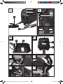
Fix the carrying strap
1
onto the
device (see Fig. C1–C4).
Connect the electrode holder
5
and
the earth terminal
4
to the welding
device.
Position an electrode in the clamps
of the electrode holder.
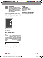
Fit welding mask
Fit the handle
8
onto the welding
mask
7
, as shown in Fig. A.
Fit the protective glass
11
on to the
welding mask
7
, as shown in
Fig.A.
The protective glass
10
must be
pushed in from the top.
Note: If you are not able to push the
protective glass
10
in fully, gently press
on the outside of the protective glass
10
.
Using the device
Note: The welding device is designed
for welding with electrodes.
Use the electrode holder clamps
without protruding bracket screws,
which meet the current safety
standards.
Safety instructions / Before use / Fit welding mask / Using the device
331996_Inverter_Schweissgeraet_PISG_120_A2_content_LB4.indb 16 05.12.19 15:41

17GB
Make sure that the ON/OFF switch
9
is set to position “O” (“OFF”)
or that the power cable
10
is not
plugged into the socket.
Connect the welding cable
according to its polarity and in
accordance with the specifications
of the electrode manufacturer.
To do this, connect the connector of
the earth terminal
4
(black) with the
relevant output on the inverter welder
(black, marked with “-”).
Connect the connector of the
electrode holder
5
(red) with the
relevant output on the inverter welder
(red, marked with “+”).
Put on appropriate protective
clothing in accordance with the
specifications and prepare your
workspace.
Connect the earth terminal
4
to the
workpiece.
Clamp the electrode into the elec-
trode holder
5
.
Switch the device on by setting the
ON/OFF switch to the
9
“I” (“ON”)
position.
Adjust the welding current using the
rotary knob
3
depending on the
electrode being used.
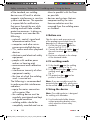
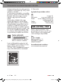
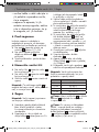
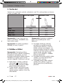
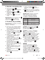
Note: See the following table for infor-
mation on the welding current to be used,
depending on the electrode diameter.
Ø Electrode Welding current
1.6 mm 40-55 A
2.0 mm 55-65 A
2.5 mm 65-80 A
3.2 mm 80-120 A
Attention: Do not bring the earth
terminal
4
and the electrode holder
5
/
electrodes into direct contact with one
another.
Attention: When welding with
electrodes (MMA – manual metal arc
welding – electrode welding), the
electrodeholder
5
and the earth
terminal
4
must be connected in
accordance with the specifications of
the welding wire to plus (+) or minus (-).
Hold the welding mask
7
in front
of the face and start the welding
procedure.
To stop the procedure, set the ON/
OFF switch
9
to “O” (“OFF”)
position.
ATTENTION!
When the thermal sensor is triggered,
the yellow control lamp
2
lights up.
In this case, it will not be possible to
continue welding. The device will
remain in operation so that the fan can
cool the device. As soon as the device
is ready for operation again, the yellow
control lamp
2
will switch off automati-
cally. The welding function can now be
used again.
ATTENTION!
Make sure that you do not rub the weld-
ing wire on the workpiece. Doing this
can damage the workpiece and make
it more difficult to ignite the arc. After
the arc is ignited, maintain the correct
gap from the workpiece. The distance
should be appropriate to the diameter
of the welding wire being used. When
welding maintain this gap as accurately
and consistently as possibly. The angle
between the welding wire and the direc-
tion of operation should be between
20° and 30°.
ATTENTION!
The welding clamp and welding wire
must be placed on the insulated bracket
after welding. Wait until the wire is
cooled before removing the welding
slag. To weld an intermittent weld seam
Using the device
331996_Inverter_Schweissgeraet_PISG_120_A2_content_LB4.indb 17 05.12.19 15:41

18 GB
again you must first remove the welding
slag at the welding position.
ATTENTION!
A voltage which is 10% below the rated
input voltage of the welding device can
have the following consequences:
The power to the device will reduce.
The arc stops or becomes unstable.
ATTENTION!
The arc radiation can lead to inflam-
mation of the eyes and skin burns.
Casting and welding slag can cause
eye injuries and burns.
Wear tinted safety goggles or a
protective mask.
The safety mask must meet the
EN175 safety standards.
It is essential that you only use the
welding cable which is included with
the delivery (10 mm
2
).
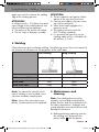
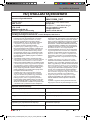
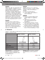
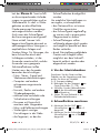
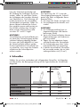
Welding
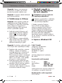
Choose between push and drag welding. The following section shows the impact of
the direction of movement on the properties of the weld seam:
Push welding Drag welding
Burn smaller larger
Weld seam width larger smaller
Weld bead flatter higher
Weld seam fault larger smaller
Note: You decide for yourself which
type of welding is most suitable, once
you have welded a sample piece.
Note: Once it has worn down com-
pletely, the electrode must be replaced.
Maintenance and
cleaning
Note: The welding device must be
regularly serviced and overhauled for
proper function and for compliance with
the safety requirements. Improper and
wrong operation may cause failures and
damage to the device.
Before performing cleaning work on
the welding tool, disconnect the
power cable
10
from the power
Using the device / Welding / Maintenance and cleaning
331996_Inverter_Schweissgeraet_PISG_120_A2_content_LB4.indb 18 05.12.19 15:41

19GB
outlet to ensure the tool is safely
isolated from the power supply.
Clean the exterior of the welding
device and its accessories regularly.
Use compressed air, cotton waste or
a brush to remove dirt and dust.
Note: The following kinds of mainte-
nance work must be performed only by
suitably-qualified personnel.
The current regulator, earthing
device, internal cables, the coupling
device of the welding torch and
adjusting screws must be serviced
regularly. Re-tighten loose screws
and replace rusty screws (replace-
ment M4x10 screws are available in
any commercial hardware store).
Check the insulation resistance levels
of the welding device regularly.
To do this use an appropriate
measuring device.
In case of a defect or a necessary
replacement of equipment parts,
please contact the appropriate
qualified personnel.
Information about
recycling and disposal
Don’t throw away – recycle
Please return this device, accesso-
ries and packaging to your local
recycling depot.
According to European Directive
2012/19/EU, used electrical devices
must be collected separately for envi-
ronmentally compatible recycling or
recovery. Please return this device to an
approved waste management company
or use your municipal waste collection
service. Please ensure you comply with
local regulations. If you have any ques-
tions, please contact your local authority
or waste management company.
EU Declaration of
Conformity
We,
C.M.C. GmbH
Responsible for documentation:
Dr Christian Weyler
Katharina-Loth-Str. 15
66386 St. Ingbert
Germany
hereby take sole responsibility for
declaring that the product
Inverter welder
Art. no.: 2249
Year of manufacture: 2020/18
IAN: 331996_1907
Model: PISG 120 A2
meets the basic safety requirements as
specified in the European Directives
EC low-voltage directive:
2014/35/EU
EC Guideline on Electromagnetic
Compatibility:
2014/30/EU
RoHS directive:
2011/65/EU+2015/863/EU
and the amendments to these Directives.
The object of the declaration described
above meets the requirements of
Directive 2011/65/EU of the European
Parliament and of the Council of
8June 2011 on the restriction of the
use of certain hazardous substances in
electrical and electronic equipment.
This conformity assessment is based on
the following harmonised standards:
... / Information about recycling and disposal / EU Declaration of Conformity
331996_Inverter_Schweissgeraet_PISG_120_A2_content_LB4.indb 19 05.12.19 15:41

20 GB
EU Declaration of Conformity / Warranty and service information
EN 60974-1:2012
EN 60974-10:2014/A1:2015
St. Ingbert, 01/10/2019
pp Dr Christian Weyler
– Quality Assurance –
Warranty and service
information
Warranty from Creative
Marketing & Consulting GmbH
Dear Customer,
The warranty for this equipment is
3years from the date of purchase. In the
event of product defects, you have legal
rights against the retailer of this product.
Your statutory rights are not affected in
any way by our warranty conditions,
which are described below.
Warranty conditions
The warranty period begins on the date
of purchase. Please retain the original
sales receipt. This document is required
as your proof of purchase.
Should this product show any defect
in materials or manufacture within
3years from the date of purchase, we
will repair or replace it – at our dis-
cretion – free of charge. This warranty
service requires that you retain proof of
purchase (sales receipt) for the defective
device for the three year period and that
you briefly explain in writing what the
fault entails and when it occurred.
If the defect is covered by our warranty,
we will repair and return your product
or send you a replacement. The original
warranty period is not extended when a
device is repair or replaced.
Warranty period and
statutory claims for
defects
The warranty period is not extended
by the guarantee. This also applies to
replaced and repaired parts. Any dam-
ages or defects detected at the time of
purchase must be reported immediately
after unpacking. Any incidental repairs
after the warranty period are subject to
a fee.
Extent of warranty
This device has been manufactured
according to strict quality guidelines and
carefully inspected before delivery.
The warranty applies to material
and manufacturing defects only. This
warranty does not extend to product
parts, which are subject to normal wear
and tear and can thus be regarded as
consumable parts, or for damages to
fragile parts, e.g. switches, rechargea-
ble batteries or parts made from glass.
This warranty is voided if the product
becomes damaged or is improperly
used or maintained. For proper use
of the product, all of the instructions
given in the operating instructions must
be followed precisely. If the operating
instructions advise you or warn you
against certain uses or actions, these
must be avoided in all circumstances.
331996_Inverter_Schweissgeraet_PISG_120_A2_content_LB4.indb 20 05.12.19 15:41
Seite wird geladen ...
Seite wird geladen ...
Seite wird geladen ...
Seite wird geladen ...
Seite wird geladen ...
Seite wird geladen ...
Seite wird geladen ...
Seite wird geladen ...
Seite wird geladen ...
Seite wird geladen ...
Seite wird geladen ...
Seite wird geladen ...
Seite wird geladen ...
Seite wird geladen ...
Seite wird geladen ...
Seite wird geladen ...
Seite wird geladen ...
Seite wird geladen ...
Seite wird geladen ...
Seite wird geladen ...
Seite wird geladen ...
Seite wird geladen ...
Seite wird geladen ...
Seite wird geladen ...
Seite wird geladen ...
Seite wird geladen ...
Seite wird geladen ...
Seite wird geladen ...
Seite wird geladen ...
Seite wird geladen ...
Seite wird geladen ...
Seite wird geladen ...
Seite wird geladen ...
Seite wird geladen ...
Seite wird geladen ...
Seite wird geladen ...
Seite wird geladen ...
Seite wird geladen ...
Seite wird geladen ...
Seite wird geladen ...
Seite wird geladen ...
Seite wird geladen ...
Seite wird geladen ...
Seite wird geladen ...
Seite wird geladen ...
Seite wird geladen ...
Seite wird geladen ...
Seite wird geladen ...
Seite wird geladen ...
Seite wird geladen ...
Seite wird geladen ...
Seite wird geladen ...
Seite wird geladen ...
Seite wird geladen ...
Seite wird geladen ...
Seite wird geladen ...
Seite wird geladen ...
Seite wird geladen ...
Seite wird geladen ...
Seite wird geladen ...
Seite wird geladen ...
Seite wird geladen ...
Seite wird geladen ...
Seite wird geladen ...
Seite wird geladen ...
Seite wird geladen ...
Seite wird geladen ...
Seite wird geladen ...
Seite wird geladen ...
Seite wird geladen ...
Seite wird geladen ...
Seite wird geladen ...
Seite wird geladen ...
Seite wird geladen ...
Seite wird geladen ...
Seite wird geladen ...
Seite wird geladen ...
Seite wird geladen ...
Seite wird geladen ...
Seite wird geladen ...
Seite wird geladen ...
Seite wird geladen ...
Seite wird geladen ...
Seite wird geladen ...
Seite wird geladen ...
Seite wird geladen ...
Seite wird geladen ...
Seite wird geladen ...
Seite wird geladen ...
Seite wird geladen ...
Seite wird geladen ...
Seite wird geladen ...
Seite wird geladen ...
Seite wird geladen ...
Seite wird geladen ...
Seite wird geladen ...
Seite wird geladen ...
-
 1
1
-
 2
2
-
 3
3
-
 4
4
-
 5
5
-
 6
6
-
 7
7
-
 8
8
-
 9
9
-
 10
10
-
 11
11
-
 12
12
-
 13
13
-
 14
14
-
 15
15
-
 16
16
-
 17
17
-
 18
18
-
 19
19
-
 20
20
-
 21
21
-
 22
22
-
 23
23
-
 24
24
-
 25
25
-
 26
26
-
 27
27
-
 28
28
-
 29
29
-
 30
30
-
 31
31
-
 32
32
-
 33
33
-
 34
34
-
 35
35
-
 36
36
-
 37
37
-
 38
38
-
 39
39
-
 40
40
-
 41
41
-
 42
42
-
 43
43
-
 44
44
-
 45
45
-
 46
46
-
 47
47
-
 48
48
-
 49
49
-
 50
50
-
 51
51
-
 52
52
-
 53
53
-
 54
54
-
 55
55
-
 56
56
-
 57
57
-
 58
58
-
 59
59
-
 60
60
-
 61
61
-
 62
62
-
 63
63
-
 64
64
-
 65
65
-
 66
66
-
 67
67
-
 68
68
-
 69
69
-
 70
70
-
 71
71
-
 72
72
-
 73
73
-
 74
74
-
 75
75
-
 76
76
-
 77
77
-
 78
78
-
 79
79
-
 80
80
-
 81
81
-
 82
82
-
 83
83
-
 84
84
-
 85
85
-
 86
86
-
 87
87
-
 88
88
-
 89
89
-
 90
90
-
 91
91
-
 92
92
-
 93
93
-
 94
94
-
 95
95
-
 96
96
-
 97
97
-
 98
98
-
 99
99
-
 100
100
-
 101
101
-
 102
102
-
 103
103
-
 104
104
-
 105
105
-
 106
106
-
 107
107
-
 108
108
-
 109
109
-
 110
110
-
 111
111
-
 112
112
-
 113
113
-
 114
114
-
 115
115
-
 116
116
-
 117
117


Parkside PISG 120 A2 Operation and Safety Notes
- Typ
- Operation and Safety Notes
- Dieses Handbuch eignet sich auch für
in anderen Sprachen
- slovenčina: Parkside PISG 120 A2
Verwandte Artikel
-
Parkside PISG 120 B3 Benutzerhandbuch
-
Parkside PISG 120 A2 Operation and Safety Notes
-
-
-
Parkside PISG 100 A1 Benutzerhandbuch
-
-
-
-
Parkside PISG 80 A2 Assembly, Operating And Safety Instructions, Translation Of The Original Instructions
-