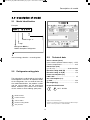
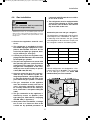
Dometic RML8230 Installationsanleitung
- Kategorie
- Fahrradzubehör
- Typ
- Installationsanleitung
Dieses Handbuch eignet sich auch für

REFRIGERAT
ION
8 SERIES
RML8230
Absorber refrigerator
Installation Manual
Absorber-Kühlschrank
Montageanleitung
EN
DE
title_16s_A4.fm Seite 1 Donnerstag, 16. Februar 2017 7:29 19

ENGLISH
Dometic Group is a customer-driven, world-leading provider of leisure products for the RV, automotive, truck and mari-
ne markets. We supply the industry and aftermarket with a complete range of air conditioners, refrigerators, awnings,
cookers, sanitation systems, lighting, mobile power equipment, comfort and safety solutions, windows, doors and other
equipment that make life more comfortable away from home.
Dometic Group supplies a wide range of workshop equipment for service and maintenance of built-in air conditioners.
Dometic Group also provides specially designed refrigerators for hotel rooms, offices, wine storage and transport and
storage of medical products.
Our products are sold in almost 100 countries and are produced mainly in wholly-owned production facilities around the
world.
DEUTSCH
Die Dometic Group ist ein kundenorientierter, weltweit führender Hersteller innovativer Komfortprodukte für den
Wohnwagen-, Reisemobil-, Lkw-, Pkw- und Bootsmarkt. Die Unternehmensgruppe beliefert dabei ebenso die Industrie,
wie den Nachrüstmarkt mit einem kompletten Sortiment von Klimaanlagen, Kühlgeräten, Markisen,
Beleuchtungssystemen, Kochgeräten, Komfort-Toiletten und Sanitärprodukten, Ausrüstungen für die mobile
Stromversorgung, Komfort- und Sicherheitslösungen, Fenstern, Türen und vielen weiteren Produkten, die das Leben
unterwegs angenehmer und bequemer machen. Darüber hinaus liefert die Dometic Group die nötige Werkstatt-
Ausrüstung für die Wartung und Reparatur von Fahrzeug-Klimaanlagen.
Die Dometic Group ist weiterhin Marktführer mit Spezialkühlschränken für Hotels, Büros und medizinische Einrichtungen
und produziert ebenso maßgeschneiderte Weinklimaschränke.
Die Produkte der Dometic Group werden in nahezu 100 Ländern der Welt verkauft und hauptsächlich in eigenen
Produktionsstätten hergestellt.
822 6102-20_RML8230_E_Umschlag_N1_Layout 1 16.07.2015 11:50 Seite 2

English
RML 8230
Installation instructions
Absorption refrigerator for recreation vehicles
EN
N 2
MBA 07/2015
Type C40 / 110
x-822 6102-20_EN_RML8230-Installation_N2_Layout 1 16.07.2015 11:08 Seite 1

2
© Dometic GmbH - 2015 - Subject to change without prior notice
Dometic GmbH
In der Steinwiese 16
D-57074 Siegen
www.dometic.com
x-822 6102-20_EN_RML8230-Installation_N2_Layout 1 16.07.2015 11:08 Seite 2

3
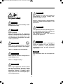
For your safety
Protect children:
When disposing of the old refrigerator,
detach all refrigerator doors and leave the
storage racks in the refrigerator. In this
way inadvertent entrappment and suffo-
cation is prevented.
WARNING!
Work on gas equipment, exhaust system
and electrical facilities must be carried
out by authorised personnel only.
Substantial damage to property and/or
injury to persons can arise through unpro-
fessional procedures.
WARNING!
Never open the absorber cooling unit! It is
under high pressure.
There is a danger of injury!
WARNING!
Never use an unshielded flame to check
gas bearing parts and pipes for leakage!
There is a danger of fire or explosion.
DANGER!
It is imperative that the operating pressu-
re corresponds to the data specified on
the rating plate of the appliance.
Any difference in values may result in
damage the appliance.
WARNING!
If the connection cable is damaged it
must be replaced by the Customer
Service at Dometic, or by respectively
qualified personnel, in order to prevent
any hazards.
CAUTION!
Pay attention to clean and residue-free
workmanship if silicone sealing com-
pound or similar is used .
There is a danger of fire if silicone threads
come into contact with hot parts or an
open flame.
WARNING!
The refrigerator must not be exposed to
rain.
CAUTION!
The appliance may be installed by autho-
rised personnel only!
WARNING!
x-822 6102-20_EN_RML8230-Installation_N2_Layout 1 16.07.2015 11:08 Seite 3

4
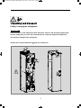
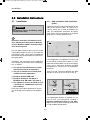
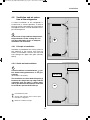
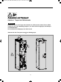
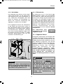
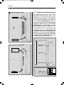
Lifting / carrying the refrigerator
Unpacking and transport
Never use parts on the refrigerator other than those shown in the illustration (particularly
not the cooling unit, gas lines and control panel) for carrying or lifting the refrigerator!
This prevents damage to the refrigerator.
Remove the transport protection (1) from the cooling unit.
CAUTION!
1
1
x-822 6102-20_EN_RML8230-Installation_N2_Layout 1 16.07.2015 11:08 Seite 4

5
1.0 General . . . . . . . . . . . . . . . . . . . . . . . . . . . . . . . . . . . . . . . . . . . . . . 6
1.1 Introduction . . . . . . . . . . . . . . . . . . . . . . . . . . . . . . . . . . . . . . . . . . . . . . . . . . . . . . . . . . . . . . . . 6
1.2 Guide to these installation instructions . . . . . . . . . . . . . . . . . . . . . . . . . . . . . . . . . . . . . . . . . . .6
1.3 Copyright protection . . . . . . . . . . . . . . . . . . . . . . . . . . . . . . . . . . . . . . . . . . . . . . . . . . . . . . . . . 6
1.4 Explanation of symbols used in this manual . . . . . . . . . . . . . . . . . . . . . . . . . . . . . . . . . . . . . . . 6
1.5 Warranty . . . . . . . . . . . . . . . . . . . . . . . . . . . . . . . . . . . . . . . . . . . . . . . . . . . . . . . . . . . . . . . . . . . 7
1.6 Limitation of liability . . . . . . . . . . . . . . . . . . . . . . . . . . . . . . . . . . . . . . . . . . . . . . . . . . . . . . . . . . 7
1.7 Declaration of conformity . . . . . . . . . . . . . . . . . . . . . . . . . . . . . . . . . . . . . . . . . . . . . . . . . . . . . . 7
1.8 Environmental notices . . . . . . . . . . . . . . . . . . . . . . . . . . . . . . . . . . . . . . . . . . . . . . . . . . . . . . . . 7
1.8.1 Disposal . . . . . . . . . . . . . . . . . . . . . . . . . . . . . . . . . . . . . . . . . . . . . . . . . . . . . . . . . . . . . . . . . . . . . . . . . . . 7
2.0 Safety instructions . . . . . . . . . . . . . . . . . . . . . . . . . . . . . . . . . . . . . . 8
2.1 Application according to regulations . . . . . . . . . . . . . . . . . . . . . . . . . . . . . . . . . . . . . . . . . . . . .8
2.2 User's responsibility . . . . . . . . . . . . . . . . . . . . . . . . . . . . . . . . . . . . . . . . . . . . . . . . . . . . . . . . . . 8
2.3 Working upon and checking the refrigerator . . . . . . . . . . . . . . . . . . . . . . . . . . . . . . . . . . . . . . . 8
2.4 Operating the refrigerator with gas . . . . . . . . . . . . . . . . . . . . . . . . . . . . . . . . . . . . . . . . . . . . . . 8
3.0 Description of model . . . . . . . . . . . . . . . . . . . . . . . . . . . . . . . . . . . . 9
3.1 Model identification . . . . . . . . . . . . . . . . . . . . . . . . . . . . . . . . . . . . . . . . . . . . . . . . . . . . . . . . . . 9
3.2 Refrigerator rating plate . . . . . . . . . . . . . . . . . . . . . . . . . . . . . . . . . . . . . . . . . . . . . . . . . . . . . . . 9
3.3 Technical data . . . . . . . . . . . . . . . . . . . . . . . . . . . . . . . . . . . . . . . . . . . . . . . . . . . . . . . . . . . . . . 9
4.0 Installation instructions . . . . . . . . . . . . . . . . . . . . . . . . . . . . . . . . . . 10
4.1 Installation . . . . . . . . . . . . . . . . . . . . . . . . . . . . . . . . . . . . . . . . . . . . . . . . . . . . . . . . . . . . . . . . . 10
4.1.1 Side installation with ventilation grilles . . . . . . . . . . . . . . . . . . . . . . . . . . . . . . . . . . . . . . . . . . . . . . . . . . . . 10
4.1.2 Rear installation . . . . . . . . . . . . . . . . . . . . . . . . . . . . . . . . . . . . . . . . . . . . . . . . . . . . . . . . . . . . . . . . . . . . . 11
4.1.3 Installation recess . . . . . . . . . . . . . . . . . . . . . . . . . . . . . . . . . . . . . . . . . . . . . . . . . . . . . . . . . . . . . . . . . . . . 11
4.1.4 Draught-proof installation . . . . . . . . . . . . . . . . . . . . . . . . . . . . . . . . . . . . . . . . . . . . . . . . . . . . . . . . . . . . . . 11
4.2 Ventilation and air extraction of the refrigerator . . . . . . . . . . . . . . . . . . . . . . . . . . . . . . . . . . . . 13
4.2.1 Principle of ventilation . . . . . . . . . . . . . . . . . . . . . . . . . . . . . . . . . . . . . . . . . . . . . . . . . . . . . . . . . . . . . . . . 13
4.2.2 Good and bad ventilation . . . . . . . . . . . . . . . . . . . . . . . . . . . . . . . . . . . . . . . . . . . . . . . . . . . . . . . . . . . . . 13
4.3 Installing the ventilation system . . . . . . . . . . . . . . . . . . . . . . . . . . . . . . . . . . . . . . . . . . . . . . . . . 14
4.3.1 Installation LS 230 . . . . . . . . . . . . . . . . . . . . . . . . . . . . . . . . . . . . . . . . . . . . . . . . . . . . . . . . . . . . . . . . . . . 15
4.4 Exhaust duct system . . . . . . . . . . . . . . . . . . . . . . . . . . . . . . . . . . . . . . . . . . . . . . . . . . . . . . . . 15
4.5 Securing the refrigerator . . . . . . . . . . . . . . . . . . . . . . . . . . . . . . . . . . . . . . . . . . . . . . . . . . . . . . 16
4.6 Gas installation . . . . . . . . . . . . . . . . . . . . . . . . . . . . . . . . . . . . . . . . . . . . . . . . . . . . . . . . . . . . . . 17
4.7 Electrical installation . . . . . . . . . . . . . . . . . . . . . . . . . . . . . . . . . . . . . . . . . . . . . . . . . . . . . . . . . . 18
4.7.1 Mains connection . . . . . . . . . . . . . . . . . . . . . . . . . . . . . . . . . . . . . . . . . . . . . . . . . . . . . . . . . . . . . . . . . . . . 18
4.7.2 Battery connection . . . . . . . . . . . . . . . . . . . . . . . . . . . . . . . . . . . . . . . . . . . . . . . . . . . . . . . . . . . . . . . . . . . 18
4.7.3 Terminal blocks . . . . . . . . . . . . . . . . . . . . . . . . . . . . . . . . . . . . . . . . . . . . . . . . . . . . . . . . . . . . . . . . . . . . . . 19
4.7.5 Wiring diagram . . . . . . . . . . . . . . . . . . . . . . . . . . . . . . . . . . . . . . . . . . . . . . . . . . . . . . . . . . . . . . . . . . . . . . 20
Table of contents
x-822 6102-20_EN_RML8230-Installation_N2_Layout 1 16.07.2015 11:08 Seite 5

6
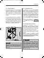
General
DANGER!
WARNING!
CAUTION!
CAUTION!
1.0 General
On installation of the appliance, the technical
and administrative regulations of the country
in which the vehicle will first be used must be
adhered to. Otherwise the refrigerator must be
installed as described in these instructions. In
Europe, for example, gas appliances, cable
routing, installation of gas cylinders, as well as
approval and checking for leaks must comply
with EN 1949 for liquid gas systems in vehi-
cles.
1.1 Introduction
Before you start installing the refrigerator,
please read the installation instructions
carefully.
These instructions provide you with the neces-
sary guidance for the proper installation of
your refrigerator. Observe in particular the
safety instructions. Observation of the
instructions and handling recommendations is
important for dealing with the refrigerator
safely and for protecting you from injury and
the refrigerator from damage. You must under-
stand what you have read before you carry out
a task.
Keep these instructions in a safe place
close to the refrigerator so they may be
referred to at any time.
1.2 Guide to these installation
instructions
The information, texts and illustrations in these
instructions are copyright protected and are
subject to industrial property rights.
No part of these instructions may be reprodu-
ced, copied or utilised in any other way wit-
hout written authorisation by Dometic GmbH,
Siegen.
1.3 Copyright protection
1.4 Explanation of symbols
used in this manual
Warning notices are identified by symbols. A
supplementary text gives you an explanation
of the degree of danger.
Observe these warning notices rigorously.
You will thus protect yourself and other
people from injury, and the appliance from
damage.
Warning notices
DANGER indicates an imminent hazardous
situation which, if not avoided, could result in
death or serious injury.
WARNING indicates a potentially hazardous
situation which, if not avoided, could result in
death or serious injury
WARNING indicates a potentially hazardous
situation which, if not avoided, could result in
death or serious injury
CAUTION (used without the safety alert sym-
bol) indicates a potentially hazardous situation
which, if not avoided, may result in damage to
the appliance.
x-822 6102-20_EN_RML8230-Installation_N2_Layout 1 16.07.2015 11:08 Seite 6

7
Information
i
1.7 Declaration of conformity
Dometic products meet the specified features
in accordance with the relevant European
standards.
The current Declaration of Conformity can be
requested directly from Dometic GmbH,
Siegen.
Ammonia (a natural compound of hydrogen
and nitrogen) is used in the cooling unit as a
coolant. Non-ozone-hazardous cyclopentane
is used as a propellant for manufacturing PU
foam insulation.
In order to ensure that the recyclable packa-
ging materials are re-used, they should be
sent to the customary local collection system.
The appliance should be transferred to a suit-
able waste disposal company that will ensure
re-use of the recyclable components and pro-
per disposal of the rest. For eco-friendly drai-
ning of the coolant from all absorber refrigera-
tion units, a suitable disposal plant should be
used.
1.8 Environmental notices
1.8.1 Disposal
Warranty arrangements are in accordance
with EC Directive 44/1999/CE and the normal
conditions applicable for the country concer-
ned. For warranty or other maintenance, plea-
se contact our customer services department.
Any damage due to improper use is not cover-
ed by the warranty. The warranty does not
cover any modifications to the appliance or
the use of non-original Dometic parts. The
warranty does not apply if the installation and
operating instructions are not adhered to and
no liability shall be entertained.
1.5 Warranty
All information and guidance in these opera-
ting instructions were prepared after taking
into consideration the applicable standards
and regulations as well as the current state of
the art. Dometic reserves the right to make
changes at any time which are deemed to be
in the interest of improving the product and
safety.
1.6 Limitation of liability
Dometic will assume no liability for damage in
the case of:
n non-observation of the operating instructi-
ons
n application not in accordance with the
regulations or provisions
n use of non-original spare parts
n modifications and interferences to the
appliance
INFORMATION gives you supplementary and
useful guidance when dealing with your refrige-
rator.
Environmental Tips
ENVIRONMENTAL TIPS gives you useful gui-
dance for saving energy and disposal of the
appliance.
General
x-822 6102-20_EN_RML8230-Installation_N2_Layout 1 16.07.2015 11:08 Seite 7

8
Safety instructions
2.0 Safety instructions
This refrigerator is designed for installation in
recreation vehicles such as caravans or
motorhomes. The appliance has been type-
approval tested for this application in accor-
dance with the EC Gas Directive.
The refrigerator is to be used solely for storing
foodstuffs.
2.1 Application according to
regulations
2.3 Working upon and checking
the refrigerator
Work on gas equipment, exhaust system
and electrical facilities must be carried
out by authorised personnel only.
Substantial damage to property and/or
injury to persons can arise through unpro-
fessional procedures.
WARNING!
Never use an unshielded flame to check
gas bearing parts and pipes for leakage!
There is a danger of fire or explosion.
DANGER!
Never open the absorber cooling unit! It is
under high pressure.
There is a danger of injury!
WARNING!
Anyone operating the refrigerator must be
familiar with the safe handling and understand
the advice in these operating instructions.
2.2 User's responsibility
It is imperative that the operating pressure
corresponds to the data specified on the
rating plate of the appliance. Compare the
operating pressure of the rating plate with the
data specified on the pressure reducing valve
of the liquid gas cylinder.
2.4 Operating the refrigerator
with gas
The refrigerator must not be exposed to
rain.
CAUTION!
x-822 6102-20_EN_RML8230-Installation_N2_Layout 1 16.07.2015 11:08 Seite 8

9
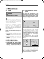
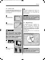
Fig. 1
2 3
4
5
1
0
manual energy selection + manual ignition
Example:
Refrigerator Mobile /
Mobile Absorption Refrigerator
"Large"
Model range "8"
RM L 8 2 3 0
0
The rating plate is to be found on the inside of
the refrigerator. It contains all important details
of the refrigerator. You can read off from this
the model identification, the product number
and the serial number. You will need these
details whenever you contact the customer
service centre or when ordering spare parts.
3.2 Refrigerator rating plate
Model number
Product number
Serial number
Electrical rating details
Gas pressure
2
1
3
4
5
Example
Description of model
3.0 Description of model
3.1 Model identification
Gross contents (litres)
Gross content (without freezer comp.)... 155.5
Freezer compartment .............................. 16.5
Dimensions (mm)
(H x W x D) ..............................1648x380x598
Electrical rating 230V (W) .................... 190
Electrical rating 12 V (W) ..................... 170
Power consumption (ca.)
kWh / 24h* .............................................. 3.5
Gas consumption (ca.)
g / 24h* ................................................... 480
Net weight (kg) ...................................... 37.0
3.3 Technical data
Inspection/Certification
Subject to technical changes.
*Average consumption measured at an average ambient tempe-
rature of 25°C in pursuance of ISO Standard.
10 R - 047358
E1
x-822 6102-20_EN_RML8230-Installation_N2_Layout 1 16.07.2015 11:08 Seite 9

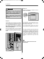
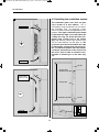
10
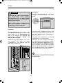
Fig. 3
Fig. 4
OK
min. 25 mm
Fig. 2
OK
Installation
4.0 Installation instructions
The unit and the exhaust duct system must be
in principle installed so that it is accessible for
maintenance work, can be easily installed and
dismantled and removed from the vehicle wit-
hout great effort.
Installation and connection of the appliance
must comply with the latest technical regulati-
ons, as follows:
n The electrical installation must comply
with national and local regulations.
n The gas installation must comply with
national and local regulations.
n European Standard EN 1949
n European Standards EN 60335-1,
EN 60335-2-24, EN 1648-1, EN 1648-2
n The appliance must be installed in such
a way that it is shielded from excessive
heat radiation.
Excessive heat impairs performance and rai-
ses the energy consumption of the refrigera-
tor!
4.1 Installation
Deviations from these installation instruc-
tions without prior notification of Dometic
result in Dometic GmbH's warranty obliga-
tions becoming void!
The appliance may be installed by autho-
rised personnel only!
WARNING!
i
4.1.1 Side installation with ventilation
grilles
If possible, do not install the refrigerator on the
side of the entrance door. An awning or a
caravan annex tent is often installed on this
side. This complicates evacuation of combu-
stion gases and heat through the ventilation
grilles (loss in cooling performance)!
If the refrigerator is installed on the same side
of the vehicle as the entrance door, it is desi-
rable that the door does not cover the refrige-
rator's vents. Otherwise ventilation could be
impaired which causes a loss in cooling per-
formance.
There must be a distance between the door
and the air vents of at least 25 mm! (Fig. 4).
If the door/grille distance is between 25 mm
and 45 mm, we recommend installing a
Dometic ventilation kit (
item no. 241 2985 -
01
) to achieve an optimal cooling performance
in high ambient temperatures.
x-822 6102-20_EN_RML8230-Installation_N2_Layout 1 16.07.2015 11:08 Seite 10

11
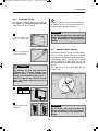
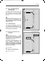
Fig. 5
Installation
4.1.2 Rear installation
Rear installation often causes an unfavourable
installation arrangement, as ideal ventilation
cannot always be assured (e.g. the ventilation
grilles are covered by installed accessories
such as bike racks!). The maximum cooling
performance of the aggregate is actually not
available.
An unfavourable method of rear installation is
to install the refrigerator lateral to the ventilati-
on grilles (Fig. 5). The air-heat recirculation is
very restricted which means that heat
exchangers (condenser, absorber) cannot be
adequately cooled. The optional method of an
additional air vent grille installed in the floor
also exhibits an insufficient air flow duct.
The maximum cooling performance is not
available! Do not apply this installation
method, as it does not provide proper ven-
tilation! Please refer to the description in
section 4.2 .
CAUTION!
The refrigerator must be installed draught-
proof in a recess. The floor of the recess must
be level, allowing the refrigerator to be pushed
easily into its correct position. The floor must
be substantial enough to bear the weight of
the appliance. Push the appliance far enough
into the recess until the front edge of the refri-
gerator casing is aligned with the front of the
recess. Allow a gap of 20 mm between the
back wall of the recess and the refrigeration
unit.
Ensure that the refrigerator
is installed level in the
recess.
4.1.3 Installation recess
Refrigerators in motorhomes, caravans or
other vehicles must be installed in a draught-
proof manner (EN 1949). This means that the
combustion air for the burner is not taken from
the living space and that exhaust fumes are
prevented from entering the living space.
Adequate sealing between the back of the
refrigerator and the vehicle interior has to be
provided.
Dometic strongly recommends carrying
this out using a flexible seal (in order to
simplify later removal and installation of the
unit for maintenance purposes.
4.1.4 Draught-proof installation
By no means use durable sealing com-
pounds, fitting foam or similar material to
realise draught-proof installation of the
refrigerator! Do NOT use any easily inflam-
mable materials for sealing (in particular
silicon sealing compound or similar). Risk
of fire! The device manufacturer's product
liability and warranty shall lapse if such
materials are used.
WARNING!
x-822 6102-20_EN_RML8230-Installation_N2_Layout 1 16.07.2015 11:08 Seite 11

12
Installation
Fig. 9
Fig. 7
Fig. 6
Fig. 8
1
1
2
2
1
The cavity in-between the outer vehicle wall
and refrigerator is completely isolated from the
vehicle interior. Intrusion of exhaust fumes into
the living space is prevented. Fumes will esca-
pe through the upper ventilation grille to the
outside. The draught-proof installation does
not require a special exhaust gas duct to be
used.
The refrigerator is later pushed into the instal-
lation recess from the front. Ensure that the
seals abut the case evenly.
This installation option facilitates the removal
and installation of the appliance for servicing.
Fasten the sealing lips to a stop bar on the rear
side (1), e.g. by gluing
Proposal 2
The lip seals (1) are installed at the bottom
and on each side in the installation recess (Fig.
6-8). A heat deflector plate (2) is installed in
the installation recess above the refrigerator.
Affix this plate to the caravan wall, do NOT
attach to the refrigerator!
Attach the deflector plate so that the heated
air escapes through the top ventilation grill into
the open air and no heat build-up can be pro-
duced.
Proposal 1
Pay attention to clean and residue-free
workmanship if silicone sealing com-
pound or similar is used elsewhere (e.g.
sealing of the ventilation grille frames).
There is a danger of fire if silicone threads
come into contact with hot parts or an
open flame.
WARNING!
Deviations require the consent of the
manufacturer!
i
x-822 6102-20_EN_RML8230-Installation_N2_Layout 1 16.07.2015 11:08 Seite 12

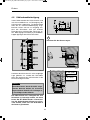
13
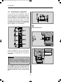
Installation
Ventilation is provided for the unit by means of
two apertures in the caravan wall. Fresh air
enters at the bottom, extracts the heat and
exits through the upper vent grille (chimney
effect).
Heat deflection plate
Air flow and reduction of the hollow space
behind the refrigerator
Minimum ventilation height
2
3
1
4.2.1 Principle of ventilation
Fig. 11
Cold air
build-up of heat
-
Ventilation
grille too low
In the event of high ambient temperatures,
full performance of the cooling unit can
only be achieved by means of adequate
ventilation and extraction.
A correct installation of the refrigerator is
essential for its correct operation, as due to
physical reasons heat builds up at the back of
the appliance which must be allowed to esca-
pe into the open air.
4.2 Ventilation and air extrac-
tion of the refrigerator
i
Avoid installations marked with the sym-
bol. Good cooling performance is not gua-
ranteed!
(Illustrations schematic)
i
-
4.2.2 Good and bad ventilation
The installation of a heat deflection plate (1)
between the refrigerator top edge and the
ventilation grille top edge is strictly requi-
red to guarantee the dissipation of the unit
heat and thus prevent heat build-up.
Fig. 10
1
Hot air
Cold air
+
1
min. 1590mm
3
x-822 6102-20_EN_RML8230-Installation_N2_Layout 1 16.07.2015 11:08 Seite 13

14
Installation
Fig. 12
2
Hot air
Cold air
+
1
Fig. 13
Cold air
1
2
-
Unit heat dissi-
pation too low!
4.3 Installing the ventilation system
The ventilation grilles must have an open
cross-section of at least 380cm². This is
achieved by using the Dometic LS 230 absor-
ber ventilation and air extraction system
which has been tested and approved for this
purpose. The upper ventilation grille should
be positioned as high as possible above the
cooling unit (Fig. 14). Install the lower ven-
tilation grille at floor level of the vehicle
(Fig. 14), allowing unburnt gas (heavier than
air) to escape directly into the open air. The
gas burner must be located above the edge
(1). Should this arrangement prove impossi-
ble, a ventilation aperture must be introdu-
ced by the manufacturer of the vehicle into
the recess floor in order to avoid the accu-
mulation of unburnt gas on the floor (Fig.
15).
1
Fig. 14
LS 230
Cooling unit
min. 1590mm
Cooling unit /
Condenser fins
LS 230
Fig. 15
Ventilation aperture
x-822 6102-20_EN_RML8230-Installation_N2_Layout 1 16.07.2015 11:08 Seite 14

15
Installation
Fig. 16
Cut two rectangles in the
exterior wall of the vehi-
cle.
1
Fig. 17
Seal the mounting frame
making it waterproof.
2
Fig. 18
Screw frame into positi-
on.
3
Fig. 19
Insert ventilation grille
and lock it.
4
4.3.1 Installation LS 230
To install the ventilation grilles, cut two rectan-
gles width a = 315 mm, height b = 373 mm,
in the outer wall of the vehicle.
b
a
14 x
Pay attention to clean and residue-free
workmanship if silicone sealing com-
pound or similar is used elsewhere (e.g.
sealing of the ventilation grille frames).
There is a danger of fire if silicone threads
come into contact with hot parts or an
open flame.
DANGER!
The exhaust gas duct system must be made in
such a manner as to achieve a complete
extraction of combustion products to the out-
side of living space. The flue gas is vented
directly through the upper grille. Do not use
any kind of aluminium flue pipe to lead the flue
gas out.
The T-piece (Fig. 21) must be aligned with the
exterior wall.
An installation other than described will
reduce the cooling capacity and jeopardi-
se the manufacturer's warranty/product
liability.
CAUTION!
4.4 Exhaust duct system
Fig. 20
45°
An installation other than described will
reduce the cooling capacity and jeopardi-
se the manufacturer's warranty/product
liability.
CAUTION!
Correct mounting of the lower ventilation gril-
le facilitates access to the connections and
functional parts during maintenance.
i
CAUTION!
2 Nm
max
100/min
max
x-822 6102-20_EN_RML8230-Installation_N2_Layout 1 16.07.2015 11:08 Seite 15

16
Installation
After the refrigerator is put in its final place,
secure the screws into the wall of the recess.
The screws must penetrate the casing of the
refrigerator.
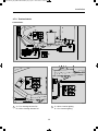
Fig. 23
Fig. 22
Fig. 24
In the sidewalls of the refrigerator, there are
eight plastic sleeves for securing the refrigera-
tor. The sidewalls or strips attached for secu-
ring the refrigerator must be prepared to hold
the screws firmly in place even when under
increased load (while the vehicle is moving).
Fastening screws and caps are supplied with
the refrigerator. Fastening screws (1) and caps
(2) are supplied with the refrigerator.
4.5 Securing the refrigerator
Always insert screws through the sleeves
provided as otherwise components laid in
foam, such as cables etc., could be dama-
ged.
The refrigerator must strictly be fastened
using eight screws (1) to ensure firm sea-
ting of the refrigerator. The cover caps can
only be inserted if a screw is in the socket
(3).
CAUTION!
Fig. 21
2
1
1
3
Note the dimensions.
i
17 mm (min)
(9,5 mm)
x-822 6102-20_EN_RML8230-Installation_N2_Layout 1 16.07.2015 11:08 Seite 16

17
Installation
4.6 Gas installation
Dometic refrigerators are equipped for a con-
nection pressure of 30 mbar. For connection
to a 50 mbar gas system, use Truma VDR
50/30 medium pressure controller.
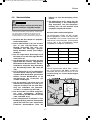
Connection pressure and gas categories
The refrigerators are operated using the gases
and inlet pressures stated below. The pressu-
re reducing valves between the gas cylinder
and refrigerator to be used must comply with
the categories stated in the following table.
Category Pressure in mbar GAS
I3B / P(30) 30 Butane
30 Propane
I3+ (28-30/37) 28-30 Butane
37 Propane
i
Fig. 25
SW 14
SW 17
1
* Qualified personnel are accredited experts who are
able, by virtue of their training and knowledge, to vouch
for the correct installation and implementation of the
leakage test.
The gas connection shall be carried out
by specialised personnel* only.
WARNING!
n Observe the regulations stated in secti-
on 4.1 .
n This refrigerator is provided for installa-
tion within liquid gas equipment in com-
pliance with EN1949 and must be run
exclusively on liquid gas (propane, buta-
ne) (no natural gas, town gas).
n A fixed, pre-set pressure regulator com-
plying with EN 12864 must be connected
to the liquid gas cylinder.
n The pressure regulator must concur with
the operating pressure specified on the
rating plate of the appliance. The opera-
ting pressure corresponds to the stan-
dard pressure of the country of specifi-
cation (EN 1949, EN 732).
n Only one connection pressure is permis-
sible for any one vehicle! A plate sho-
wing the permanent, clearly legible noti-
ce must be displayed in full view at the
point where the gas cylinder is installed.
n The gas connection to the appliance
must be installed securely and free of
stress using pipe connectors and must
be securely connected to the vehicle (a
hose connection is not permissible) (EN
1949).
n The gas connection to the appliance is
effected by means of (Ermeto-) olive
type fitting L8, DIN 2353-ST, complying
with EN 1949 (s. figure 23,1).
n After professional installation, a leakage
test as well as a flame test have to be
carried out by qualified personnel* in
conformity with EN 1949. A test certifica-
te has to be issued.
n The refrigerator must be equipped with a
shut-off valve allowing to cut the supply
line. Such a shut-off device must be rea-
dily accessible to the user.
x-822 6102-20_EN_RML8230-Installation_N2_Layout 1 16.07.2015 11:08 Seite 17

18
Installation
Fig. 26
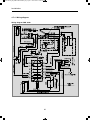
4.7.2 Battery connection
The machine's 12V connection cable is con-
nected (observing correct polarity) to a termi-
nal strip. The wiring for the 12V heating ele-
ment (refer to A, B wiring diagram connecti-
ons) must be direct and by the shortest possi-
ble route to the battery or electric generator.
Cable cross sections and cable lengths:
Motorcaravan & Caravan (inside)
6 mm
²
< 6 m
10 mm
²
> 6 m
Caravan (outside)
min 2,5 mm
²
(EN1648-1)
2,5mm²
In order to ensure that the 12V power supply is
shut off when stopping the engine (otherwise
the battery would discharge within a few
hours), perform the power supply to the 12V
heating element (connection A/B in wiring dia-
gram) in a way to have the 12V supply only live
while the vehicle ignition is switched on.
Provide a 20 A fuse to protect on-board 12V
circuit.
The connection C/D (interior light, cable
black/violet) must be permanently provided by
a 12V DC power supply to be protected by a
2A fuse.
If the appliance is installed in a caravan
the respective leads for the 12V+ and 12V-
connections A/B and C/D must not be
connected to each other on the caravan-
side (EN 1648-1).
CAUTION!
* Specialised personnel are accredited experts who are
able, by virtue of their training and knowledge, to vouch
for the correct installation. .
4.7 Electrical installation
n The electrical installation must be in
accordance with the national regulations
of the respective countries.
n The connection cables must be routed in
a way to prevent contact with hot com-
ponents of the unit/burner or with sharp
edges.
n Cable cross-sections must be large
enough to avoid performance degradati-
on of the refrigerator by high voltage
drop on the cable.
n Changes to the internal electrical instal-
lation or the connection of other electri-
cal components (e.g. external fan) to the
internal wiring of the appliance will ren-
der the E1/ CE admittance as well as any
claims from warranty and product liabili-
ty void!
4.7.1 Mains connection
n The power should be supplied by a pro-
perly grounded socket outlet or a groun-
ded non-detachable connection. Where
a socket outlet with mains supply is
used, the outlet must be freely accessi-
ble. We recommend leading the power
supply via a board-side fuse protection.
n Should the connection cable be dama-
ged, have it replaced by Dometic
Customer Services or by qualified per-
sonnel to avoid hazards.
The electrical installation shall be carried
out by qualified personnel* only.
WARNING!
x-822 6102-20_EN_RML8230-Installation_N2_Layout 1 16.07.2015 11:08 Seite 18
Seite wird geladen ...
Seite wird geladen ...
Seite wird geladen ...
Seite wird geladen ...
Seite wird geladen ...
Seite wird geladen ...
Seite wird geladen ...
Seite wird geladen ...
Seite wird geladen ...
Seite wird geladen ...
Seite wird geladen ...
Seite wird geladen ...
Seite wird geladen ...
Seite wird geladen ...
Seite wird geladen ...
Seite wird geladen ...
Seite wird geladen ...
Seite wird geladen ...
Seite wird geladen ...
Seite wird geladen ...
Seite wird geladen ...
Seite wird geladen ...
Seite wird geladen ...
Seite wird geladen ...
-
 1
1
-
 2
2
-
 3
3
-
 4
4
-
 5
5
-
 6
6
-
 7
7
-
 8
8
-
 9
9
-
 10
10
-
 11
11
-
 12
12
-
 13
13
-
 14
14
-
 15
15
-
 16
16
-
 17
17
-
 18
18
-
 19
19
-
 20
20
-
 21
21
-
 22
22
-
 23
23
-
 24
24
-
 25
25
-
 26
26
-
 27
27
-
 28
28
-
 29
29
-
 30
30
-
 31
31
-
 32
32
-
 33
33
-
 34
34
-
 35
35
-
 36
36
-
 37
37
-
 38
38
-
 39
39
-
 40
40
-
 41
41
-
 42
42
-
 43
43
-
 44
44


Dometic RML8230 Installationsanleitung
- Kategorie
- Fahrradzubehör
- Typ
- Installationsanleitung
- Dieses Handbuch eignet sich auch für
in anderen Sprachen
- English: Dometic RML8230 Installation guide
Verwandte Artikel
-
Dometic RMD8501, RMD8505, RMD8551, RMD8555 Installationsanleitung
-
-
-
-
Dometic RM 8501 Benutzerhandbuch
-
-
Dometic DVF Holding Tank Vent Filter Bedienungsanleitung
-
-