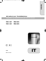
Dometic RMD8501, RMD8505, RMD8551, RMD8555 Installationsanleitung
- Typ
- Installationsanleitung

REFRIGERATION
REFRIGERATORS
RMD8501, RMD8505, RMD8551,
RMD8555
Absorber refrigerator
Installation Manual
Absorber-Kühlschrank
Montageanleitung
Réfrigérateur à absorption
Instructions de montage
Frigorifero ad assorbimento
Indicazioni di montaggio
EN
DE
FR
IT
title_16s_A4.fm Seite 1 Donnerstag, 16. Februar 2017 3:47 15


RMD 8501 RMD 8505
RMD 8551 RMD 8555
MBA 07/2012
N 2
Installation instructions
Absorption refrigerator for recreation vehicles
EN
English
289 0318-20_EN_RMD8xxx-Installation_N2.qxp 25.07.2012 10:05 Seite 1

2
© Dometic GmbH - 2012 - Subject to change without prior notice
Dometic GmbH
In der Steinwiese 16
D-57074 Siegen
www.dometic.com
289 0318-20_EN_RMD8xxx-Installation_N2.qxp 25.07.2012 10:05 Seite 2

1.0 General . . . . . . . . . . . . . . . . . . . . . . . . . . . . . . . . . . . . . . . . . . . . . . 4
1.1 Introduction . . . . . . . . . . . . . . . . . . . . . . . . . . . . . . . . . . . . . . . . . . . . . . . . . . . . . . . . . . . . . . . . 4
1.2 Guide to these operating instructions . . . . . . . . . . . . . . . . . . . . . . . . . . . . . . . . . . . . . . . . . . . .4
1.3 Copyright protection . . . . . . . . . . . . . . . . . . . . . . . . . . . . . . . . . . . . . . . . . . . . . . . . . . . . . . . . . 4
1.4 Explanation of symbols used in this manual . . . . . . . . . . . . . . . . . . . . . . . . . . . . . . . . . . . . . . . 4
1.5 Warranty . . . . . . . . . . . . . . . . . . . . . . . . . . . . . . . . . . . . . . . . . . . . . . . . . . . . . . . . . . . . . . . . . . . 5
1.6 Limitation of liability . . . . . . . . . . . . . . . . . . . . . . . . . . . . . . . . . . . . . . . . . . . . . . . . . . . . . . . . . . 5
1.7 Declaration of conformity . . . . . . . . . . . . . . . . . . . . . . . . . . . . . . . . . . . . . . . . . . . . . . . . . . . . . . 5
2.0 Safety instructions . . . . . . . . . . . . . . . . . . . . . . . . . . . . . . . . . . . . . . 6
2.1 Application according to regulations . . . . . . . . . . . . . . . . . . . . . . . . . . . . . . . . . . . . . . . . . . . . .6
2.2 User's responsibility . . . . . . . . . . . . . . . . . . . . . . . . . . . . . . . . . . . . . . . . . . . . . . . . . . . . . . . . . . 6
2.3 Working upon and checking the refrigerator . . . . . . . . . . . . . . . . . . . . . . . . . . . . . . . . . . . . . . . 6
2.4 Operating the refrigerator with gas . . . . . . . . . . . . . . . . . . . . . . . . . . . . . . . . . . . . . . . . . . . . . . 6
3.0 Description of model . . . . . . . . . . . . . . . . . . . . . . . . . . . . . . . . . . . . 7
3.1 Model identification . . . . . . . . . . . . . . . . . . . . . . . . . . . . . . . . . . . . . . . . . . . . . . . . . . . . . . . . . . 7
3.2 Refrigerator rating plate . . . . . . . . . . . . . . . . . . . . . . . . . . . . . . . . . . . . . . . . . . . . . . . . . . . . . . . 7
3.3 Technical data . . . . . . . . . . . . . . . . . . . . . . . . . . . . . . . . . . . . . . . . . . . . . . . . . . . . . . . . . . . . . . 8
4.0 Installation instructions . . . . . . . . . . . . . . . . . . . . . . . . . . . . . . . . . . 9
4.1 Installation . . . . . . . . . . . . . . . . . . . . . . . . . . . . . . . . . . . . . . . . . . . . . . . . . . . . . . . . . . . . . . . . . 9
4.1.1 Side installation . . . . . . . . . . . . . . . . . . . . . . . . . . . . . . . . . . . . . . . . . . . . . . . . . . . . . . . . . . . . . . . . . . . . . . 9
4.1.2 Rear installation . . . . . . . . . . . . . . . . . . . . . . . . . . . . . . . . . . . . . . . . . . . . . . . . . . . . . . . . . . . . . . . . . . . . . 10
4.1.3 Draught-proof installation . . . . . . . . . . . . . . . . . . . . . . . . . . . . . . . . . . . . . . . . . . . . . . . . . . . . . . . . . . . . . . 10
4.2 Installation recess . . . . . . . . . . . . . . . . . . . . . . . . . . . . . . . . . . . . . . . . . . . . . . . . . . . . . . . . . . . . 12
4.2.1 Installation in the recess . . . . . . . . . . . . . . . . . . . . . . . . . . . . . . . . . . . . . . . . . . . . . . . . . . . . . . . . . . . . . . . 12
4.3 Ventilation . . . . . . . . . . . . . . . . . . . . . . . . . . . . . . . . . . . . . . . . . . . . . . . . . . . . . . . . . . . . . . . . . 12
4.3.1 Ventilation and air extraction of the refrigerator . . . . . . . . . . . . . . . . . . . . . . . . . . . . . . . . . . . . . . . . . . . . . 12
4.3.2 Height of ventilation . . . . . . . . . . . . . . . . . . . . . . . . . . . . . . . . . . . . . . . . . . . . . . . . . . . . . . . . . . . . . . . . . . 13
4.4 Installing the ventilation system . . . . . . . . . . . . . . . . . . . . . . . . . . . . . . . . . . . . . . . . . . . . . . . . . 14
4.4.1 Installation LS300 . . . . . . . . . . . . . . . . . . . . . . . . . . . . . . . . . . . . . . . . . . . . . . . . . . . . . . . . . . . . . . . . . . . . 14
4.4.2 Installation roof exhaust R500 . . . . . . . . . . . . . . . . . . . . . . . . . . . . . . . . . . . . . . . . . . . . . . . . . . . . . . . . . . 14
4.5 Exhaust duct system . . . . . . . . . . . . . . . . . . . . . . . . . . . . . . . . . . . . . . . . . . . . . . . . . . . . . . . . 15
4.6 Securing the refrigerator . . . . . . . . . . . . . . . . . . . . . . . . . . . . . . . . . . . . . . . . . . . . . . . . . . . . . . 15
4.7 Insert the decor panel . . . . . . . . . . . . . . . . . . . . . . . . . . . . . . . . . . . . . . . . . . . . . . . . . . . . . . . . 16
4.8 Gas installation . . . . . . . . . . . . . . . . . . . . . . . . . . . . . . . . . . . . . . . . . . . . . . . . . . . . . . . . . . . . . . 17
4.9 Electrical installation . . . . . . . . . . . . . . . . . . . . . . . . . . . . . . . . . . . . . . . . . . . . . . . . . . . . . . . . . . 18
4.9.1 Mains connection . . . . . . . . . . . . . . . . . . . . . . . . . . . . . . . . . . . . . . . . . . . . . . . . . . . . . . . . . . . . . . . . . . . . 18
4.9.2 Battery connection . . . . . . . . . . . . . . . . . . . . . . . . . . . . . . . . . . . . . . . . . . . . . . . . . . . . . . . . . . . . . . . . . . . 19
4.9.3 Cable connections . . . . . . . . . . . . . . . . . . . . . . . . . . . . . . . . . . . . . . . . . . . . . . . . . . . . . . . . . . . . . . . . . . . 19
4.9.4 D+ and solar connection . . . . . . . . . . . . . . . . . . . . . . . . . . . . . . . . . . . . . . . . . . . . . . . . . . . . . . . . . . . . . . 21
4.9.5 Wiring diagrams . . . . . . . . . . . . . . . . . . . . . . . . . . . . . . . . . . . . . . . . . . . . . . . . . . . . . . . . . . . . . . . . . . . . . 22
3
Table of contents
289 0318-20_EN_RMD8xxx-Installation_N2.qxp 25.07.2012 10:05 Seite 3

4
General
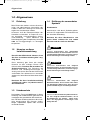
1.0 General
On installation of the appliance, the technical
and administrative regulations of the country
in which the vehicle will first be used must be
adhered to. Otherwise the refrigerator must be
installed as described in these instructions. In
Europe, for example, gas appliances, cable
routing, installation of gas cylinders, as well as
approval and checking for leaks must comply
with EN 1949 for liquid gas systems in vehi-
cles.
1.1 Introduction
The information, texts and illustrations in these
instructions are copyright protected and are
subject to industrial property rights.
No part of these instructions may be reprodu-
ced, copied or utilised in any other way wit-
hout written authorisation by Dometic GmbH,
Siegen, Germany.
1.3 Copyright protection
Before you start installing the refrigerator,
please read the installation instructions
carefully.
These instructions provide you with the neces-
sary guidance for the proper installation of
your refrigerator. Observe in particular the
safety instructions. Observation of the
instructions and handling recommendations is
important for dealing with the refrigerator
safely and for protecting you from injury and
the refrigerator from damage. You must under-
stand what you have read before you carry out
a task.
Keep these instructions in a safe place
close to the refrigerator so they may be
referred to at any time.
1.2 Guide to these installation
instructions
1.4 Explanation of symbols
used in this manual
Warning notices are identified by symbols. A
supplementary text gives you an explanation
of the degree of danger.
Observe these warning notices rigorously.
You will thus protect yourself and other
people from injury, and the appliance from
damage.
Warning notices
DANGER indicates an imminent hazardous
situation which, if not avoided, could result in
death or serious injury.
DANGER!
WARNING indicates a potentially hazardous
situation which, if not avoided, could result in
death or serious injury
WARNING!
CAUTION indicates a potentially hazardous
situation which, if not avoided, may result in
minor or moderate injury.
CAUTION!
CAUTION (used without the safety alert sym-
bol) indicates a potentially hazardous situation
which, if not avoided, may result in damage to
the appliance.
CAUTION!
289 0318-20_EN_RMD8xxx-Installation_N2.qxp 25.07.2012 10:05 Seite 4

5
General
All information and guidance in these opera-
ting instructions were prepared after taking
into consideration the applicable standards
and regulations as well as the current state of
the art. Dometic reserves the right to make
changes at any time which are deemed to be
in the interest of improving the product and
safety.
Dometic will assume no liability for damage in
the case of :
non-observation of the operating instructi-
ons
application not in accordance with the
regulations or provisions
use of non-original spare parts
modifications and interferences to the
appliance
effect of environmental influences, such as
- temperature fluctuations
- humidity
1.6 Limitation of liability
1.7 Declaration of conformity
Information
INFORMATION gives you supplementary and
useful guidance when dealing with your refrige-
rator.
Environmental Tips
ENVIRONMENTAL TIPS gives you useful gui-
dance for saving energy and disposal of the
appliance.
Warranty arrangements are in accordance
with EC Directive 44/1999/CE and the normal
conditions applicable for the country concer-
ned. For warranty or other maintenance, plea-
se contact our customer services department.
Any damage due to improper use is not cover-
ed by the warranty. The warranty does not
cover any modifications to the appliance or
the use of non-original Dometic parts. The
warranty does not apply if the installation and
operating instructions are not adhered to and
no liability shall be entertained.
1.5 Warranty
289 0318-20_EN_RMD8xxx-Installation_N2.qxp 25.07.2012 10:05 Seite 5

6
Safety instructions
2.0 Safety instructions
This refrigerator is designed for installation in
recreation vehicles such as caravans or
motorhomes. The appliance has been type-
approval tested for this application in accor-
dance with the EC Gas Directive.
The refrigerator is to be used solely for storing
foodstuffs.
2.1 Application according to
regulations
2.3 Working upon and checking
the refrigerator
Work on gas equipment, exhaust system
and electrical facilities must be carried
out by authorised personnel only.
Substantial damage to property and/or
injury to persons can arise through unpro-
fessional procedures.
WARNING!
Never use an unshielded flame to check
gas bearing parts and pipes for leakage!
There is a danger of fire or explosion.
DANGER!
Never open the absorber cooling unit! It is
under high pressure.
There is a danger of injury!
WARNING!
Anyone operating the refrigerator must be
familiar with the safe handling and understand
the advice in these operating instructions.
2.2 User's responsibility
It is imperative that the operating pressure
corresponds to the data specified on the
rating plate of the appliance. Compare the
operating pressure of the rating plate with the
data specified on the pressure reducing valve
of the liquid gas cylinder.
2.4 Operating the refrigerator
with gas
The refrigerator must not be exposed to
rain.
CAUTION!
289 0318-20_EN_RMD8xxx-Installation_N2.qxp 25.07.2012 10:05 Seite 6

7
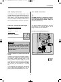
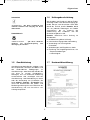
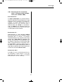
RM
8 5 0 1
1
5
D
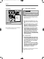
Refrigerator Mobile /
Mobile Absorption Refrigerator
1 = manual energy selection, automatic igni-
tion (MES)
5 = automatic and manual energy selection,
automatic ignition (AES)
Model range
5 = Width 523mm
Depth:
0 = Standard
5 = + 55mm
6 = + 65mm
Double door refrigerator
Example:
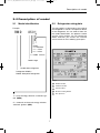
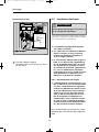
Model number
Product number
Serial number
Electrical rating details
Gas pressure
2
1
3
4
5
Description of model
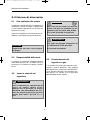
3.0 Description of model
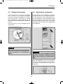
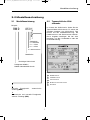
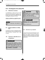
3.1 Model identification
The rating plate is to be found on the inside of
the refrigerator. It contains all important details
of the refrigerator. You can read off from this
the model identification, the product number
and the serial number. You will need these
details whenever you contact the customer
service centre or when ordering spare parts.
3.2 Refrigerator rating plate
Fig. 1
2
1
3
4
5
Example
289 0318-20_EN_RMD8xxx-Installation_N2.qxp 25.07.2012 10:05 Seite 7

8
Description of model
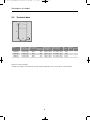
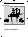
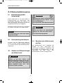
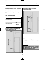
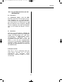
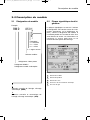
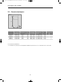
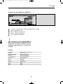
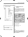
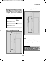
3.3 Technical data
Model Dimensions Gross capacity
Rating details
Consumption * Net Ignition
H x W x D (mm) with freezer compartment mains/battery electricity/gas weight Piezo Automat
Depth incl. door freezer com over 24hrs
Fig. 2
RMD 8xxx
H
W
D
RMD 8501
RMD 8505
RMD 8551
RMD 8555
1245x523x567
1245x523x567
1245x523x622
1245x523x622
160 lit.
160 lit.
190 lit.
190 lit.
40 kg
40 kg
41.5 kg
41.5 kg
30 lit.
30 lit.
35 lit.
35 lit.
190 W / 170 W
190 W / 170 W
190 W / 170 W
190 W / 170 W
•
•
•
•
ca.3,2 KWh / 380 g
ca.3,2 KWh / 380 g
ca.3,2 KWh / 380 g
ca.3,2 KWh / 380 g
Subject to technical changes.
*Average consumption measured at an average ambient temperature of 25°C in pursuance of ISO Standard.
289 0318-20_EN_RMD8xxx-Installation_N2.qxp 25.07.2012 10:05 Seite 8

9
Installation
4.0 Installation instructions
The unit and the exhaust duct system must be
in principle installed so that it is accessible for
maintenance work, can be easily installed and
dismantled and removed from the vehicle wit-
hout great effort.
Installation and connection of the appliance
must comply with the latest technical regulati-
ons, as follows:
The electrical installation must comply
with national and local regulations.
The gas installation must comply with
national and local regulations.
European Standards EN 1949
European Standards EN 60335-1,
EN 60335-2-24, EN 1648-1 , EN 1648-2
The appliance must be installed in such
a way that it is shielded from excessive
heat radiation.
Excessive heat impairs performance and rai-
ses the energy consumption of the refrigera-
tor!
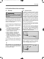
4.1 Installation
Deviations from these installation instructi-
ons without prior notification of Dometic
result in Dometic GmbH's warranty obliga-
tions becoming void!
The appliance may be installed by autho-
rised personnel only!
WARNING!
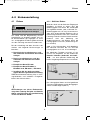
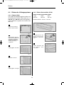
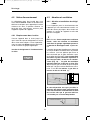
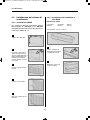
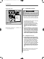
(Fig. 4 )The air vent grilles offer an unobstruc-
ted dissipation of heat and exhaust gas even
when the door is opened.
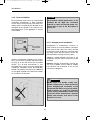
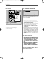
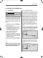
4.1.1 Side installation
If the appliance is installed on the same side of
the vehicle as the entrance door, it is desirable
that the door does not cover the refrigerator's
vents. (Fig. 3, Clearance door/ventilation grille
at least 25 mm). Otherwise ventilation could
be impaired which causes a loss in cooling
performance. Awnings are often placed at the
door side of a caravan. This complicates eva-
cuation of combustion gases and heat through
the ventilation grilles (loss in cooling perfor-
mance)!
(Fig. 3) The air vent grilles are blocked. There
must be a distance between the door and the
air vents of at least 25 mm!
If the door/grille distance is between 25 mm
and 45 mm, we recommend installing a
Dometic ventilation kit
(item no. 241 2985 -
00/0)
to achieve an optimal cooling perfor-
mance in high ambient temperatures.
Fig. 3
Fig. 4
Air vent grille not
blocked!
OK!
289 0318-20_EN_RMD8xxx-Installation_N2.qxp 25.07.2012 10:05 Seite 9

10
Installation
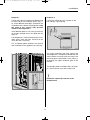
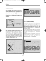
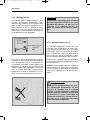
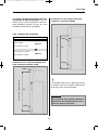
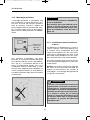
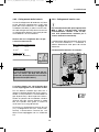
Another unfavourable method of rear installa-
tion is to install the air intake and exhaust gril-
les (Fig. 6) at the side wall of the recreation
vehicle. The air-heat recirculation is very
restricted which means that heat exchangers
(condenser, absorber) cannot be adequately
cooled. The optional method of an additional
air vent grille installed in the floor also exhibits
an insufficient air flow duct.
Fig. 5
Air vent grille
not blocked!
OK!
4.1.2 Rear installation
Rear installation often causes an unfavourable
installation arrangement, as ideal ventilation
cannot always be assured (e.g. the lower ven-
tilation grille is covered by the bumper or the
rear lights of the vehicle!). The maximum coo-
ling performance of the aggregate is actually
not available.
The maximum cooling performance is not
available! Do not apply this installation
method, as it does not provide proper ven-
tilation! Please refer to the description in
section 4.2.
CAUTION!
Fig. 6
4.1.3 Draught-proof installation
Refrigerators in motorhomes, caravans or
other vehicles must be installed in a draught-
proof manner (EN 1949). This means that the
combustion air for the burner is not taken from
the living space and that exhaust fumes are
prevented from entering the living space.
Adequate sealing between the back of the
refrigerator and the vehicle interior has to be
provided.
Dometic strongly recommends carrying this
out using a flexible seal (in order to simplify
later removal and installation of the unit for
maintenance purposes.
By no means use durable sealing com-
pounds, fitting foam or similar material to
realise draught-proof installation of the
refrigerator! Do NOT use any easily inflam-
mable materials for sealing (in particular
silicon sealing compound or similar). Risk
of fire! The device manufacturer's product
liability and warranty shall lapse if such
materials are used.
WARNING!
289 0318-20_EN_RMD8xxx-Installation_N2.qxp 25.07.2012 10:05 Seite 10

11
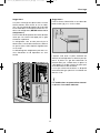
Installation
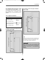
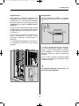
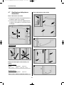
The lip seals (1) are installed at the bottom and
on each side in the installation recess (Fig. 7-
9). A heat deflector plate (2) is installed in the
installation recess above the refrigerator. Affix
this plate to the caravan wall, do NOT
attach to the refrigerator !
Insert deflector plate in such a way that the hot
air escapes through the air vent grille into the
open air.
The refrigerator is later pushed into the instal-
lation recess from the front. Ensure that the
seals abut the case evenly.
This installation option facilitates the removal
and installation of the appliance for servicing.
Abb. 8
Fig. 7
Fig. 9
1
1
2
2
Proposal 1
The cavity in-between the outer vehicle wall
and refrigerator is completely isolated from the
vehicle interior. Intrusion of exhaust fumes into
the living space is prevented. Fumes will esca-
pe through the upper ventilation grille to the
outside.
The draught-proof installation does not requi-
re a special exhaust gas duct to be used. .
Deviations require the consent of the
manufacturer!
Fig. 10
Fasten the sealing lips to a stop bar on the
rear side (1), e.g. by gluing.
1
Proposal 2
289 0318-20_EN_RMD8xxx-Installation_N2.qxp 25.07.2012 10:05 Seite 11

12
Installation
In the event of high ambient temperatures,
full performance of the cooling unit can
only be achieved by means of adequate
ventilation and extraction.
A correct installation of the refrigerator is
essential for its correct operation, as due to
physical reasons heat builds up at the back of
the appliance which must be allowed to esca-
pe into the open air.
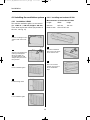
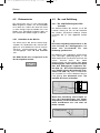
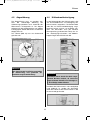
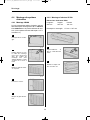
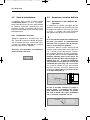
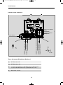
4.3.1 Ventilation and air extraction of
the refrigerator
4.3 Ventilation
Ventilation is provided for the unit by means of
two apertures in the caravan wall. Fresh air
enters at the bottom, extracts the heat and
exits through the upper vent grille (chimney
effect). The upper ventilation grille should
be positioned as high as possible above the
condenser (Fig. 13) . Install the lower ven-
tilation grille at floor level of the vehicle
(Fig. 16), allowing unburnt gas (heavier than
air) to escape directly into the open air. The
gas burner must be located above the edge
(1) .
Fig. 11
1
Fig. 12
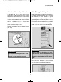
Should this arrangement prove impossible,
a ventilation aperture must be introduced
by the manufacturer of the vehicle into the
recess floor in order to avoid the accumula-
tion of unburnt gas on the floor.
ventilation aperture
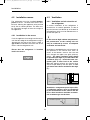
4.2.1 Installation in the recess
Push the appliance far enough into the recess
until the front edge of the refrigerator casing is
aligned with the front of the recess. Allow a
gap of 20 mm between the back wall of the
recess and the refrigeration unit.
Ensure that the refrigerator is installed
level in the recess.
The refrigerator must be installed draught-
proof in a recess . The floor of the recess must
be level, allowing the appliance to be pushed
easily into its correct position. The floor must
be substantial enough to bear the weight of
the appliance.
4.2 Installation recess
289 0318-20_EN_RMD8xxx-Installation_N2.qxp 25.07.2012 10:05 Seite 12

13
Installation
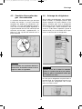
Fig. 14
Minimum height of ventilation
LS300
LS300
H
Installation of lower and upper ventilation
grilles LS300.
Correct mounting of the lower ventilation gril-
le facilitates access to the connections and
functional parts during maintenance.
An installation other than described will
reduce the cooling capacity and jeopardi-
se the manufacturer's warranty/product
liability.
CAUTION!
Minimum height of ventilation H
1.
☺☺☺☺☺☺
☺☺☺☺☺☺
Roof exhaust R500
1250 mm
Lower vent grille LS300
2.
☺☺☺☺
☺☺☺☺
Upper vent grille LS300
1400 mm
Lower vent grille LS300
Fig. 13
4.3.2 Height of ventilation
Minimum height of ventilation
R500
LS300
H
The ventilation grilles must have an open
cross-section of at least 400cm². This is
achieved by using the Dometic LS 300 absor-
ber ventilation and air extraction system
which has been tested and approved for this
purpose.
Installation of roof exhaust R500 and lower
ventilation grille LS300.
289 0318-20_EN_RMD8xxx-Installation_N2.qxp 25.07.2012 10:05 Seite 13

14
Installation
Fig. 21
Seal the installation
bays and screw them
to the vehicle roof.
1
Fig. 22
Place the hood in
postion and screw it
to the installation
bays.
2
Measurements of roof exhaust R 500
Length Width Height
595 mm 205 mm 150 mm
Roof cut out: 87mm X 507 mm
Fig. 20
4.4.2 Installing roof exhaust R 500
4.4 Installing the ventilation system
Fig. 15
Cut two rectangles in the
exterior wall of the vehi-
cle.
1
Fig. 16
Seal the mounting frame
making it waterproof
(
does not apply for
mounting frames with
integral seal)
and screw
into position.
2
Fig. 17
Insert ventilation grille.
3
Fig. 18
Install locking slider.
4
Fig. 19
Lock ventilation grille.
5
4.4.1 Installation LS300
To install the ventilation grilles, cut two rectan-
gles width b = 490 mm, height a 249 mm,
in the outer wall of the vehicle (for position of
the cuts, see Fig. 14).
b
a
14 x
289 0318-20_EN_RMD8xxx-Installation_N2.qxp 25.07.2012 10:05 Seite 14

15
The exhaust gas duct system must be made in
such a manner as to achieve a complete
extraction of combustion products to the out-
side of living space. The flue gas is vented
directly through the upper grille. Do not use
any kind of aluminium flue pipe to lead the flue
gas out.
The T-piece (Fig. 23) must be aligned with the
exterior wall.
An installation other than described will
reduce the cooling capacity and jeopardi-
se the manufacturer's warranty/product
liability.
CAUTION!
Installation
4.5 Exhaust duct system
After the refrigerator is put in its final place,
secure the screws into the wall of the recess.
The screws must penetrate the casing of the
refrigerator.
Fig. 24
Fig. 25
In the sidewalls of the refrigerator, there are
four plastic sleeves for securing the refrigera-
tor. The sidewalls or strips attached for secu-
ring the refrigerator must be prepared to hold
the screws firmly in place even when under
increased load (while the vehicle is moving).
Fastening screws and caps are supplied with
the refrigerator.
4.6 Securing the refrigerator
Always insert screws through the sleeves
provided as otherwise components laid in
foam, such as cables etc., could be dama-
ged.
CAUTION!
Fig. 23
45°
289 0318-20_EN_RMD8xxx-Installation_N2.qxp 25.07.2012 10:05 Seite 15

16
Installation
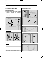
4.7 Insert the decor panel
Fig. 27
Fig. 28
Fig. 26
Fig. 29
1
2
Decor panel dimensions (frame) :
300 +/- 1 mm 507,5 +/- 1 mm max. 1.7 mm
Upper door
Height Width Thickness
907,4 +/- 1 mm 507,5 +/- 1 mm max. 1.7 mm
Lower door
Height Width Thickness
CAUTION!
3
4
2
1
Frameless decor panel
Decor panel with frame
Remove the lateral ledge (1) from the door
(ledge is attached, not screwed).
Shift decor panel (2) away from the door
and insert the new decor panel. Re-attach
ledge (1).
Fig. 30
1
Fig. 33
Fig. 31 Fig. 32
3
4
2
289 0318-20_EN_RMD8xxx-Installation_N2.qxp 25.07.2012 10:05 Seite 16

17
Installation
* Qualified personnel are accredited experts who are
able, by virtue of their training and knowledge, to vouch
for the correct installation and implementation of the lea-
kage test.
4.8 Gas installation
The gas connection shall be carried out
by qualified personnel* only.
WARNING!
Observe the regulations stated in secti-
on 4.1 .
This refrigerator is provided for installati
on within liquid gas equipment in com-
pliance with EN1949 and must be run
exclusively on liquid gas (propane, buta-
ne) (no natural gas, town gas).
A fixed, pre-set pressure regulator com-
plying with EN 12864 must be connected
to the liquid gas cylinder.
The pressure regulator must concur with
the operating pressure specified on the
rating plate of the appliance. The opera-
ting pressure corresponds to the stan-
dard pressure of the country of specifi-
cation (EN 1949, EN 732).
Only one connection pressure is permis
sible for any one vehicle! A plate sho-
wing the permanent, clearly legible noti-
ce must be displayed in full view at the
point where the gas cylinder is installed.
The gas connection to the appliance
must be installed securely and free of
stress using pipe connectors and must
be securely connected to the vehicle (a
hose connection is not permissible) (EN
1949).
The gas connection to the appliance is
effected by means of (Ermeto-) olive
type fitting L8, DIN 2353-ST, complying
with EN 1949 ( s. figure 34).
After professional installation, a leakage
test as well as a flame test have to be
carried out by qualified personnel* in
conformity with EN 1949. A test certifica-
te has to be issued.
The refrigerator must be equipped with a
shut-off valve allowing to cut the supply
line. Such a shut-off device must be
readily accessible to the user.
Dometic refrigerators are equipped for a con-
nection pressure of 30 mbar. For connection
to a 50 mbar gas system, use Truma VDR
50/30 medium pressure controller.
Connection pressure and gas categories
The refrigerators are operated using the gases
and inlet pressures stated below. The pressu-
re reducing valves between the gas cylinder
and refrigerator to be used must comply with
the categories stated in the following table.
Category Pressure in mbar GAS
I3B / P(30) 30 Butane
30 Propane
I3+ (28-30/37) 28-30 Butane
37 Propane
289 0318-20_EN_RMD8xxx-Installation_N2.qxp 25.07.2012 10:05 Seite 17

18
Installation
Gas connection
Fig. 34
SW 14
SW 17
CAUTION!
20 Nm
max
10 Nm
max
(Ermeto-) Olive type fitting L8,
(EN ISO 8434)
1
The electrical installation must be in
accordance with the national regulations
of the respective countries.
The connection cables must be routed in
a way to prevent contact with hot
components of the unit/burner or with
sharp edges.
Changes to the internal electrical instal-
lation or the connection of other electri-
cal components (e.g. external fan) to the
internal wiring of the appliance will ren-
der the e1/ CE admittance as well as any
claims from warranty and product liabili-
ty void!
* Specialised personnel are accredited experts who are
able, by virtue of their training and knowledge, to vouch
for the correct installation.
4.9 Electrical installation
The electrical installation shall be carried
out by qualified personnel* only.
WARNING!
4.9.1 Mains connection
The power should be supplied by a pro-
perly grounded socket outlet or a groun-
ded non-detachable connection. Where
a socket outlet with mains supply is
used, the outlet must be freely accessi-
ble.
Should the connection cable be dama-
ged, have it replaced by Dometic
Customer Services or by qualified per
sonnel to avoid hazards.
We recommend leading the power supply via
a board-side fuse protection.
289 0318-20_EN_RMD8xxx-Installation_N2.qxp 25.07.2012 10:05 Seite 18
Seite wird geladen ...
Seite wird geladen ...
Seite wird geladen ...
Seite wird geladen ...
Seite wird geladen ...
Seite wird geladen ...
Seite wird geladen ...
Seite wird geladen ...
Seite wird geladen ...
Seite wird geladen ...
Seite wird geladen ...
Seite wird geladen ...
Seite wird geladen ...
Seite wird geladen ...
Seite wird geladen ...
Seite wird geladen ...
Seite wird geladen ...
Seite wird geladen ...
Seite wird geladen ...
Seite wird geladen ...
Seite wird geladen ...
Seite wird geladen ...
Seite wird geladen ...
Seite wird geladen ...
Seite wird geladen ...
Seite wird geladen ...
Seite wird geladen ...
Seite wird geladen ...
Seite wird geladen ...
Seite wird geladen ...
Seite wird geladen ...
Seite wird geladen ...
Seite wird geladen ...
Seite wird geladen ...
Seite wird geladen ...
Seite wird geladen ...
Seite wird geladen ...
Seite wird geladen ...
Seite wird geladen ...
Seite wird geladen ...
Seite wird geladen ...
Seite wird geladen ...
Seite wird geladen ...
Seite wird geladen ...
Seite wird geladen ...
Seite wird geladen ...
Seite wird geladen ...
Seite wird geladen ...
Seite wird geladen ...
Seite wird geladen ...
Seite wird geladen ...
Seite wird geladen ...
Seite wird geladen ...
Seite wird geladen ...
Seite wird geladen ...
Seite wird geladen ...
Seite wird geladen ...
Seite wird geladen ...
Seite wird geladen ...
Seite wird geladen ...
Seite wird geladen ...
Seite wird geladen ...
Seite wird geladen ...
Seite wird geladen ...
Seite wird geladen ...
Seite wird geladen ...
Seite wird geladen ...
Seite wird geladen ...
Seite wird geladen ...
Seite wird geladen ...
Seite wird geladen ...
Seite wird geladen ...
Seite wird geladen ...
Seite wird geladen ...
Seite wird geladen ...
Seite wird geladen ...
Seite wird geladen ...
Seite wird geladen ...
Seite wird geladen ...
Seite wird geladen ...
-
 1
1
-
 2
2
-
 3
3
-
 4
4
-
 5
5
-
 6
6
-
 7
7
-
 8
8
-
 9
9
-
 10
10
-
 11
11
-
 12
12
-
 13
13
-
 14
14
-
 15
15
-
 16
16
-
 17
17
-
 18
18
-
 19
19
-
 20
20
-
 21
21
-
 22
22
-
 23
23
-
 24
24
-
 25
25
-
 26
26
-
 27
27
-
 28
28
-
 29
29
-
 30
30
-
 31
31
-
 32
32
-
 33
33
-
 34
34
-
 35
35
-
 36
36
-
 37
37
-
 38
38
-
 39
39
-
 40
40
-
 41
41
-
 42
42
-
 43
43
-
 44
44
-
 45
45
-
 46
46
-
 47
47
-
 48
48
-
 49
49
-
 50
50
-
 51
51
-
 52
52
-
 53
53
-
 54
54
-
 55
55
-
 56
56
-
 57
57
-
 58
58
-
 59
59
-
 60
60
-
 61
61
-
 62
62
-
 63
63
-
 64
64
-
 65
65
-
 66
66
-
 67
67
-
 68
68
-
 69
69
-
 70
70
-
 71
71
-
 72
72
-
 73
73
-
 74
74
-
 75
75
-
 76
76
-
 77
77
-
 78
78
-
 79
79
-
 80
80
-
 81
81
-
 82
82
-
 83
83
-
 84
84
-
 85
85
-
 86
86
-
 87
87
-
 88
88
-
 89
89
-
 90
90
-
 91
91
-
 92
92
-
 93
93
-
 94
94
-
 95
95
-
 96
96
-
 97
97
-
 98
98
-
 99
99
-
 100
100


Dometic RMD8501, RMD8505, RMD8551, RMD8555 Installationsanleitung
- Typ
- Installationsanleitung
in anderen Sprachen
Verwandte Artikel
-
Dometic ABSORPTION RMD 8555 Installationsanleitung
-
Dometic RMD 8501 Operating Instructions Manual
-
-
-
-
Dometic RMDT8501, RMDT8505, RMDT8551, RMDT8555 Installationsanleitung
-
-
-
-