Krone Camera Monitor System Bedienungsanleitung
- Typ
- Bedienungsanleitung

Enclose this document with the operating instructions of the
machine.
Supplement to operating
instructions
Document number: 150000893_03_en
Version: 03/05/2022
for accessories kit:
B288 – Camera Monitor System
Mowing technology

2Supplement to operating instructions 150000893_03_en
Contact
Maschinenfabrik Bernard Krone GmbH & Co. KG
Heinrich-Krone-Straße 10
48480 Spelle
Germany
Telephone main office + 49 (0) 59 77/935-0
Telefax main office + 49 (0) 59 77/935-339
Telefax spare parts warehouse na-
tional territory
+ 49 (0) 59 77/935-239
Telefax spare parts warehouse export + 49 (0) 59 77/935-359
Internet www.landmaschinen.krone.de
https://mediathek.krone.de/
For information on your KRONE machines, also refer to mykrone.green. After you have
registered, you can generate and manage your machines via the machine number so that you
can view the machine data. Via your personal account, you can also access all KRONE
Services.
Information for enquiries and orders
Year
Machine number
Type
Contact data of your dealer

Table of contents
Supplement to operating instructions 150000893_03_en 3
1 Information on this document ..................................................................................................4
1.1 Validity .........................................................................................................................................4
1.2 Re-ordering ..................................................................................................................................4
1.3 Further applicable documents......................................................................................................4
2 Safety ..........................................................................................................................................5
2.1 Meaning of the supplement to the operating instructions ............................................................5
3 Description of the machine.......................................................................................................6
3.1 Camera Monitor System ..............................................................................................................6
4 Start-up .......................................................................................................................................7
4.1 Connect the Camera Monitor System..........................................................................................7
5 Operation ....................................................................................................................................9
5.1 Operating the Camera Monitor System .......................................................................................9
6 Driving and transport ..............................................................................................................10
6.1 Prepare the machine for road travel ..........................................................................................10
7 Settings.....................................................................................................................................11
7.1 Configure/check the Camera Monitor System ...........................................................................11
8 Appendix...................................................................................................................................14
9 Index..........................................................................................................................................80

1 Information on this document
1.1 Validity
4 Supplement to operating instructions 150000893_03_en
1 Information on this document
1.1 Validity
This document is valid for:
Accessories kit: B288 – Camera Monitor System
Machine type: EasyCut F 320 EasyCut F 320 CR
EasyCut F 320 CV EasyCut F 320 M
EasyCut F 360 CR EasyCut F 360 CV
EasyCut F 360 M MT203-20 (EasyCut F 280 High-
land)
MT203-30 (EasyCut F 320 High-
land)
MT203-53 (EasyCut F 400 CV
Fold)
1.2 Re-ordering
You can request a replacement document if this document became completely or partly
unusable, or if you need it in a different language. Please specify the document number shown
on the cover page in your order. Alternatively, you can download the document online from
KRONE MEDIA https://media.mykrone.green.
1.3 Further applicable documents
To ensure that the machine is used safely and as intended, observe the following further
applicable documents.
• Operating instructions of the respective machine
• Instructions of the monitor manufacturer
• German Agricultural Society DLG test report 6301

Safety 2
Meaning of the supplement to the operating instructions 2.1
Supplement to operating instructions 150000893_03_en 5
2 Safety
WARNING
Risk of injury due to non-observance of relevant safety instructions
If the relevant safety instructions are not observed, persons may be seriously injured or killed.
In order to avoid accidents, the relevant safety instructions in the operating instructions
must be read and observed.
WARNING
Risk of injury due to non-observance of safety routines
If the relevant safety routines are not observed, persons may be seriously injured or killed.
In order to avoid accidents, the safety routines in the operating instructions must be read
and observed.
INFO
Depending on the machine type, the basic safety instructions can be found in the chapter
“Safety”, “Basic Safety Instructions” or in the chapter “Safety” of the machine operating
instructions.
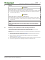
2.1 Meaning of the supplement to the operating instructions
The supplement to the operating instructions is an important document and a part of the
machine. It is aimed at the user and contains safety-relevant information.
If the supplement to the operating instructions is not observed, people may be seriously injured
or killed.
Read in full and observe the “Safety” chapter of the corresponding operating instructions
before using the machine for the first time,see Page4.
Before working, also read and observe the respective sections of the corresponding
operating instructions,see Page4.
Keep the supplement to the operating instructions ready to hand for the user of the machine.
Hand over the supplement to the operating instructions to subsequent users.

3 Description of the machine
3.1 Camera Monitor System
6 Supplement to operating instructions 150000893_03_en
3 Description of the machine
3.1 Camera Monitor System
For Germany only
WARNING
Risk of accident when using an unsuitable camera-monitor system
Camera-monitor systems which do not comply with the requirements of the manufacturer may
impair the operational safety of the machine and cause accidents.
üThe camera-monitor system described in this document is used.
To ensure safe operation on the machine side as well as on the tractor side, only use the
components (cameras, monitors, connection cables) which are described in this
document.
By giving the certification mark "DLG Approved" analogue to Part A and Part B, the DLG testing
commission considers the camera-monitor system an "appropriate measure" to replace the
guide for hitched work machines with a front end dimension exceeding ≤3.5m described in
leaflet published in the Verkehrsblatt from November 27th 2009.
DLG Test Center for Technology and Farm Inputs is a multiple accredited testing laboratory.
Among other things, it is accredited by the Federal Motor Transport Authority for field of vision
inspections. The camera-monitor system tested by the DLG reduces the restriction of the field of
vision caused by the exceeding of the front construction dimension to such an extent that an
exemption according to §70Road Traffic Approval Order (StVZO) exists or corresponding
conditions are dropped (e.g. accompanying persons).
When driving on roads,the DLG test report serves as a proof described above.

Start-up 4
Connect the Camera Monitor System 4.1
Supplement to operating instructions 150000893_03_en 7
4 Start-up
WARNING
Risk of injury due to failure to observe the operating instructions
If the operating instructions are not followed, people may be seriously injured or killed.
To avoid accidents, the operating instructions must be read and observed.
Observe the warnings in the respective chapter of the operating instructions.
4.1 Connect the Camera Monitor System
7
1
3
4
2
11
10
6
5
89
BEI000-095
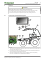
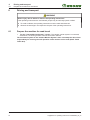
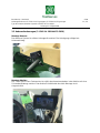
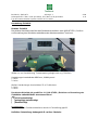
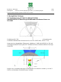
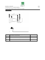
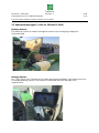
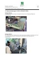
üThe monitor must be fixed within the driver’s cabin in such a way as to ensure the driver has
the monitor within the field of vision.
Be careful to ensure that none of the display instruments are covered and that the field of
vision of the driver is not obscured from the front.
Shut down and safeguard the machine, refer to the Safety chapter in the operating
instructions, “Shutting Down and Safeguarding the Machine”.

4 Start-up
4.1 Connect the Camera Monitor System
8 Supplement to operating instructions 150000893_03_en
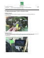
Monitor connection to the tractor
Connect the plug (10) of the cable (6) to the socket (CAM1) of the monitor (1).
Connect the plug (11) of the cable (6) to the socket (CAM2) of the monitor (1).
Connect the plug (2) of the cable (3) to the socket (POWER) of the monitor (1).
Connect the plug (4) of the cable (3) to the socket of 12 Volt of the monitor of the tractor (5).
Connection from Tractor to the machine
The Camera Monitor System is connected with the 13-pin connecting cable (8) included in the
delivery.
Connect the 13-pin plug of the connecting cable (8) with the 13-pin socket (9) of the
machine.
Connect the 13-pin plug of the connecting cable (8) with the 13-pin socket (7) of the tractor.
Lay the cable such that it is not allowed to rub, be tightened, pinched or otherwise come into
contact with other components, particularly when laid in corners.

Operation 5
Operating the Camera Monitor System 5.1
Supplement to operating instructions 150000893_03_en 9
5 Operation
WARNING
Risk of injury due to failure to observe the operating instructions
If the operating instructions are not followed, people may be seriously injured or killed.
To avoid accidents, the operating instructions must be read and observed.
Observe the warnings in the respective chapter of the operating instructions.
5.1 Operating the Camera Monitor System
• To operate the Camera Monitor System please refer to the instructions of the monitor
manufacturer.

6 Driving and transport
6.1 Prepare the machine for road travel
10 Supplement to operating instructions 150000893_03_en
6 Driving and transport
WARNING
Risk of injury due to failure to observe the operating instructions
If the operating instructions are not followed, people may be seriously injured or killed.
To avoid accidents, the operating instructions must be read and observed.
Observe the warnings in the respective chapter of the operating instructions.
6.1 Prepare the machine for road travel
ü For the "Camera Monitor System" version: The camera monitor system is connected,
switched on, functioning and the cameras have been cleaned.
The assistance system in the "Camera Monitor System" does not exempt the driver from
responsibility for ensuring the safe operation of the machine on the road (StVO - Road
Traffic Act).

Settings 7
Configure/check the Camera Monitor System 7.1
Supplement to operating instructions 150000893_03_en 11
7 Settings
WARNING
Risk of injury due to failure to observe the operating instructions
If the operating instructions are not followed, people may be seriously injured or killed.
To avoid accidents, the operating instructions must be read and observed.
Observe the warnings in the respective chapter of the operating instructions.
7.1 Configure/check the Camera Monitor System
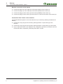
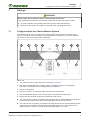
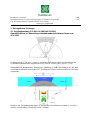
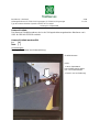
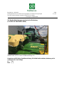
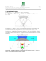
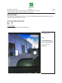
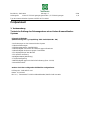
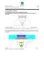
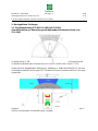
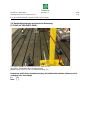
The defined field of view is composed of the direct field of view(6) and the camera field of
view(5). The camera-monitor system must be adjusted so that points(1) to(4) are visible on
the monitor on the left and right sides respectively.
2
3
4
1
5
4
3
2
1
566
KM001-349
üThe camera-monitor system has been connected, see Page7.
Shut down and safeguard the machine, refer to the Safety chapter in the operating
instructions, “Shutting Down and Safeguarding the Machine”.
Switch on the ignition.
Switch the monitor on, see the monitor manufacturer's instructions.
Call up the divided display mode, see the monitor manufacturer's instructions.
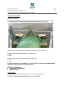
Ensure that the cameras are properly connected to the monitor.
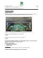
ÆThe cameras are properly connected if the right-hand side of the divided display shows the
picture from the right camera and the left-hand side that from the left camera.
ÆThe cameras are not properly connected if the right-hand side of the divided display shows
the picture from the left camera and the left-hand side that from the right camera. If the
display sides are reversed, change the plugs(CAM1/CAM2), see Page7.

7 Settings
7.1 Configure/check the Camera Monitor System
12 Supplement to operating instructions 150000893_03_en
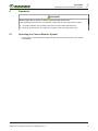
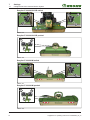
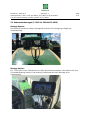
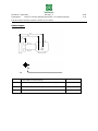
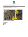
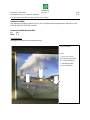
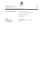
EasyCut F 320/360 CV/CR trailed
77
8
9
8
9
KM000-476
EasyCut F 320/360 CV/CR pushed
78
9
KM001-350
EasyCut F 320/360 M trailed
77
8
9
8
9
KM001-351
EasyCut F 320/360 M pushed
78
9
KM001-352

Settings 7
Configure/check the Camera Monitor System 7.1
Supplement to operating instructions 150000893_03_en 13
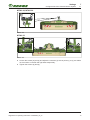
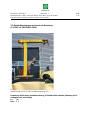
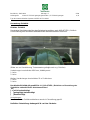
MT203-20, MT203-30
78
9
KM001-353
MT203-53
77
8
9
8
9
KM001-354
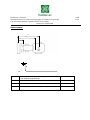
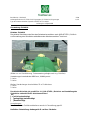
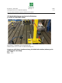
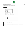
Loosen the screws(8) and(9) and adjust the cameras(7) so that points(1) to(4) are visible
on the monitor on the left and right sides respectively.
Tighten the screws(8) and(9).


Berichts-Nr.: 2202-043 Seite
Anbaugerät: Krone EC F320 CV/CR gezogen, EC F360 CV/CR gezogen 1 / 13
Typ des Kamera-Monitor-Systems: MOTEC KIT-1-VKMS
Geschäftsführer: Rudolf Hepp, Stefano Mastrogiovanni
Sitz der Organisation: Gau-Bickelheim
Amtsgericht Mainz HRB 40800
USt-IdNr.: DE114139855
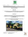
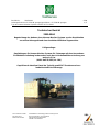
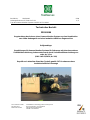
Technischer Bericht
2202-043
Begutachtung des Anbaus eines Kamera-Monitor-Systems an eine Kombination
aus einem Anbaugerät und einer landwirtschaftlichen Zugmaschine
Prüfgrundlage:
Empfehlungen für Kamera-Monitor-Systeme für Fahrzeuge mit einer besonderen
Sichtfeldeinschränkung insbesondere auch durch Vorbaumaßüberschreitung von
mehr als 3,5 m
(VkBl. Heft 23/2016, Nr. 180)
Geprüft nach aktuellem Stand der Technik gemäß FKT-Sonderausschuss
landwirtschaftliche Fahrzeuge

Berichts-Nr.: 2202-043 Seite
Anbaugerät: Krone EC F320 CV/CR gezogen, EC F360 CV/CR gezogen 2 / 13
Typ des Kamera-Monitor-Systems: MOTEC KIT-1-VKMS
Tabelle der Änderungen
Es wird korrigiert:
Es wird geändert:
Es wird hinzugefügt:
Es entfällt:
1
Geprüfte Gerätekombinationen
Vorbau-Kamera-Monitor-
System
MOTEC KIT-1-VKMS
Prüfungs-Nr.: 2018-00507 rev0
Datum: 22.10.2018, DLG e.V., Testzentrum
Technik und Betriebsmittel, 64823 Groß-
Umstadt.
Landwirtschaftliche
Zugmaschine
Anbaugerät(e)
Amtl. Kennzeichen:
EL YY833
-
Hersteller:
DEERE (USA)
KRONE Agriculture SE
Typ:
L003
EC F320 CV gezogene Version
EC F320 CR gezogene Version
EC F360 CV gezogene Version
EC F360 CR gezogene Version
Variante:
GD44
-
Handelsbezeichnung:
6170M
-
Identifizierungs-Nr.:
1L06170MTFK84172
Masch.-Nr. 993645

Berichts-Nr.: 2202-043 Seite
Anbaugerät: Krone EC F320 CV/CR gezogen, EC F360 CV/CR gezogen 3 / 13
Typ des Kamera-Monitor-Systems: MOTEC KIT-1-VKMS
Hinweis:
Dieser Bericht beinhaltet den Nachweis der Vorschriftsmäßigkeit des Anbaus eines Kamera-
Monitor-Systems bei einer Kombination aus einer lof-Zugmaschine und einem Anbaugerät.
In diesem Fall sind das Kamera-System am Anbaugerät und das Monitor-System an der
Zugmaschine montiert. Der Nachweis der Erfüllung der Anforderungen zum Kamera-Anbau
am Anbaugerät wurde beispielhaft mit dem beschriebenen Fahrzeug nachgewiesen.
Der Bericht kann als Arbeitsgrundlage bei Einzelbegutachtungen nach StVZO § 19 (2) von
Anbaugeräten mit Kamera-Systemen der beschriebenen Typen an anderen lof-
Zugmaschinentypen dienen.
Dabei sind folgende Hinweise zu beachten:
Die Sichtfeldprüfung erfolgt gemäß 2.5 der Prüfgrundlage. Die Prüfgrundlage dient dabei als
Ergänzung der Richtlinie zur Beurteilung des Sichtfelds selbstfahrender Arbeitsmaschinen.
Bezüglich der direkten Sicht des Fahrzeugführers sind daher weiterhin die Anforderungen
der Richtlinie zur Beurteilung des Sichtfelds selbstfahrender Arbeitsmaschinen zu erfüllen.
Die in der Prüfgrundlage veröffentlichte beispielhafte Zeichnung ist dahingehend
missverständlich und wurde bereits durch den „FKT-Sonderausschuss landwirtschaftliche
Fahrzeuge“ angepasst und soll bei der nächsten Überarbeitung und Veröffentlichung der
Empfehlung korrigiert werden. Bei der Durchführung der Sichtfeldmessung (Anlage 2.1 –
Ziffer 2.1) ist die korrigierte Zeichnung zu verwenden.
Die Prüfung der Anbauanforderungen erfolgt gemäß Ziffer 3 der Prüfgrundlage. Dabei sind
insbesondere der Anbau des Monitors und die Installation der Verbindungsleitungen gemäß
Montageanleitung zu prüfen.
Gemäß der Prüfgrundlage sind Anbauprüfungen nur in Verbindung mit dem Anbau
konkreter Typen von Anbaugeräten zulässig. Bei Fahrzeugbegutachtungen sind daher die
Typbezeichnungen der Anbaugeräte im Gutachten aufzunehmen, bzw. in Feld 22 der
Zulassungsbescheinigung einzutragen.
Erfüllt das Kamera-Monitor-System die Sichtfeldanforderungen in allen möglichen
Einstellungen des Anbaugeräts, muss keine Fahrposition definiert und angezeigt werden.
Ansonsten ist die zulässige Fahrstellung des Fahrzeugs oder des Anbaugeräts zur
Einhaltung des Sichtfelds zu definieren.
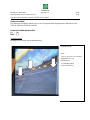
Die Fahrzeugfront (Anbaugerät) ist beidseitig durch rot-weiße retroreflektierende
Schrägschraffierung zu kennzeichnen.
Das geprüfte maximal zulässige Vorbaumaß beträgt 5,03 m.

Berichts-Nr.: 2202-043 Seite
Anbaugerät: Krone EC F320 CV/CR gezogen, EC F360 CV/CR gezogen 4 / 13
Typ des Kamera-Monitor-Systems: MOTEC KIT-1-VKMS
2
Anhänge
2.1
Prüfprotokoll
3
Anlagen
3.1
Montageanleitung und
Bedienungsanleitung

Berichts-Nr.: 2202-043 Seite
Anbaugerät: Krone EC F320 CV/CR gezogen, EC F360 CV/CR gezogen 5 / 13
Typ des Kamera-Monitor-Systems: MOTEC KIT-1-VKMS
4
Zusammenfassung und Auflagen
Die aufgeführten Installationen des geprüften Kamera-Monitor-Systems
entsprechen der Prüfgrundlage (siehe Hinweis unter Ziffer 1).
Dieser Bericht darf nur vom Auftraggeber und nur in vollem Wortlaut vervielfältigt
und weitergegeben werden. Eine auszugsweise Vervielfältigung und
Veröffentlichung des Berichtes ist nur nach schriftlicher Genehmigung zulässig.
Die Prüfung wurde durchgeführt gemäß den relevanten Anforderungen der
EN ISO/IEC 17025:2005
EN ISO/IEC 17020:2012
PRÜFLABOR
DLG TestService GmbH
ist vom Kraftfahrt-Bundesamt
als Technischer Dienst der Kategorie A, B und D benannt.
Bundesrepublik Deutschland unter Registrier-Nr.:
KBA-P 00020-19
Unterschriftsberechtigter
Qualitätskontrolle
Jürgen Goldmann
Stefano Mastrogiovanni
Groß-Umstadt, den 24.03.2022

Berichts-Nr.: 2202-043 Seite
Anbaugerät: Krone EC F320 CV/CR gezogen, EC F360 CV/CR gezogen 6 / 13
Typ des Kamera-Monitor-Systems: MOTEC KIT-1-VKMS
Anhang 2.1 Prüfprotokoll
Prüfprotokoll
1. Vorbemerkung
Technische Prüfung des Fahrzeuganbaus eines Vorbau-Kamera-Monitor-
Systems
Folgende Prüfinhalte:
(Nummerierung laut o.g. Empfehlung VkBl. Heft 23/2016 Nr. 180)
2. Anforderungen an das Kamera-Monitor-System
2.1 Basisanforderungen
2.2 Elektromagnetische Verträglichkeit
2.3 Beständigkeit von Monitor und Kamera gegen Vibrationen
2.4 Beständigkeit der Kamera gegen Chemikalien
2.5.2 Objektgröße auf dem Monitor
2.5.3 Optische Auflösung
2.6 Gegenlichttest („Blooming“)
2.7 Signalverzögerung
2.8 Beständigkeit gegen mechanische Belastung (Satz 1: IP69)
2.9 Ausfallsicherheit
wurden durch den vorliegenden Prüfbericht nachgewiesen:
Prüfungs-Nr.: 2018-00507 rev0
Datum: 22.10.2018
DLG e.V., Testzentrum Technik und Betriebsmittel, 64823 Groß-Umstadt.
Seite wird geladen ...
Seite wird geladen ...
Seite wird geladen ...
Seite wird geladen ...
Seite wird geladen ...
Seite wird geladen ...
Seite wird geladen ...
Seite wird geladen ...
Seite wird geladen ...
Seite wird geladen ...
Seite wird geladen ...
Seite wird geladen ...
Seite wird geladen ...
Seite wird geladen ...
Seite wird geladen ...
Seite wird geladen ...
Seite wird geladen ...
Seite wird geladen ...
Seite wird geladen ...
Seite wird geladen ...
Seite wird geladen ...
Seite wird geladen ...
Seite wird geladen ...
Seite wird geladen ...
Seite wird geladen ...
Seite wird geladen ...
Seite wird geladen ...
Seite wird geladen ...
Seite wird geladen ...
Seite wird geladen ...
Seite wird geladen ...
Seite wird geladen ...
Seite wird geladen ...
Seite wird geladen ...
Seite wird geladen ...
Seite wird geladen ...
Seite wird geladen ...
Seite wird geladen ...
Seite wird geladen ...
Seite wird geladen ...
Seite wird geladen ...
Seite wird geladen ...
Seite wird geladen ...
Seite wird geladen ...
Seite wird geladen ...
Seite wird geladen ...
Seite wird geladen ...
Seite wird geladen ...
Seite wird geladen ...
Seite wird geladen ...
Seite wird geladen ...
Seite wird geladen ...
Seite wird geladen ...
Seite wird geladen ...
Seite wird geladen ...
Seite wird geladen ...
Seite wird geladen ...
Seite wird geladen ...
Seite wird geladen ...
Seite wird geladen ...
Seite wird geladen ...
Seite wird geladen ...
-
 1
1
-
 2
2
-
 3
3
-
 4
4
-
 5
5
-
 6
6
-
 7
7
-
 8
8
-
 9
9
-
 10
10
-
 11
11
-
 12
12
-
 13
13
-
 14
14
-
 15
15
-
 16
16
-
 17
17
-
 18
18
-
 19
19
-
 20
20
-
 21
21
-
 22
22
-
 23
23
-
 24
24
-
 25
25
-
 26
26
-
 27
27
-
 28
28
-
 29
29
-
 30
30
-
 31
31
-
 32
32
-
 33
33
-
 34
34
-
 35
35
-
 36
36
-
 37
37
-
 38
38
-
 39
39
-
 40
40
-
 41
41
-
 42
42
-
 43
43
-
 44
44
-
 45
45
-
 46
46
-
 47
47
-
 48
48
-
 49
49
-
 50
50
-
 51
51
-
 52
52
-
 53
53
-
 54
54
-
 55
55
-
 56
56
-
 57
57
-
 58
58
-
 59
59
-
 60
60
-
 61
61
-
 62
62
-
 63
63
-
 64
64
-
 65
65
-
 66
66
-
 67
67
-
 68
68
-
 69
69
-
 70
70
-
 71
71
-
 72
72
-
 73
73
-
 74
74
-
 75
75
-
 76
76
-
 77
77
-
 78
78
-
 79
79
-
 80
80
-
 81
81
-
 82
82


Krone Camera Monitor System Bedienungsanleitung
- Typ
- Bedienungsanleitung
Verwandte Artikel
-
Krone Camera Monitor System Bedienungsanleitung
-
-
Krone BA EasyCut F 360 CV/CR Bedienungsanleitung
-
-
Krone BA EasyCut R 280 CR Bedienungsanleitung
-
Krone BA EasyCut R 320 CR Bedienungsanleitung
-
-