
Einbauanleitung / Installation Guide
0456010 PMC-Eight Goto Upgrade Kit – Losmandy G11

DE
Lieferumfang:
Explore Scientific PMC-8 Goto Upgrade Set
PMC-Eight Controller mit Halter
Zwei Schrittmotoren mit Gehäuse
Zwei Flexkupplungen für die direkte Verbindung der Schneckenwellen
Losmandy G11 RA Achsverlängerung
Zwei hochwertige serielle Motorkabel
Netzteil 240Volt/12Volt 3A
Montage- und Bedienungsanleitung per Download
Explore Scientific™ ExploreStars App per Download
ASCOM + INDI Treiber per Download
SOFTWARE DOWNLOAD:
https://www.explorescientific.de/Software-und-Downloads-fuer-PMC-Eight-System/
Erforderliches Werkzeug: Innensechskantschlüssel 5/32", 3/16", 7/64", 5/64", 1/16" (Zoll)
Bitte überprüfen Sie den Lieferumfang und lesen Sie die komplette Anleitung vor Beginn der
Installationsarbeiten sorgfältig durch.
GB
Scope of Delivery:
Explore Scientific Open GOTO PMC-8 upgrade kit
PMC-Eight controller box with mounting adapter
Two stepper motors with housing
Two flex couplers for direct connection to the worm blocks
Losmandy RA Extension
Two durable serial cables
AC adapter 240V / 12V 3A
Installation guide and user manual via download
Explore Scientific™s free ExploreStars software via download
ASCOM + INDI Driver via download
SOFTWARE DOWNLOAD
https://explorescientificusa.com/pages/software-and-downloads-for-pmc-eight-system
Necessary tools: Hex Wrench 5/32", 3/16", 7/64", 5/64", 1/16"
Please check the scope of delivery and read the complete manual carefully before starting
the installation work.

Arbeitsschritte / Working steps:
1. DE: Entfernen der alten Motoren, soweit vorhanden.
GB: Remove old motor drives if they are present.

2. DE: Entfernen der Schneckenwellen-Abdeckung und der Lagerböcke.
GB: Remove worm cover and and worm assembly.

3. DE: Enfernen der DEC Einheit und der Scheckenrad-Abdeckung.
GB: Remove Dec Assembly and Main gear cover.
4. DE: Enfernen Scheckenrad Einheit und der Abdeckung.
GB: Remove Main gear Assembly and Main gear plate.

5. DE: Einfräsen einer Längsnut in die Motorplatte (13x23x3,6mm).
GB: Machining the elongated groove at the motor plate(13x23x3,6mm) .

6. DE: RA Einheit montieren und die Schnecke mit dem Hauptgetriebe verbinden.
ACHTUNG: Dies ist ein kritischer Arbeitsschritt. Das Schneckengetriebe darf nur und
muss aber ein geringes Spiel haben und sich 360 Grad leicht und gleichmäßig drehen.
Sie müssen das Lager von Hand vorspannen und gleichzeitig die Schrauben leicht
andrehen, während Sie die Schnecke drehen das Scheckenspiel fortwährend
überprüfen.
GB: Assemble RA and Mess the worm to the Main gear.
ATTENTION: This step is the critical, the mess of the worm need to have no lash and
rotate 360 deg extremely smooth you need to preload the bearing by hand an at the
same time tite the screws lightly as you check the mess and rotating the worm.
7. DE: RA Achsverlängerung installieren.
GB: Installation of the RA Extension .


8. DE: Zusammenbau der DEC Einheit genauso wie die RA Einheit. Achten Sie
besonders auf eine exakte Einstellung des Schneckenspiels. Lieber etwas mehr Spiel
zulassen als zu wenig !
GB: Assembly the Dec same way as the RA pay attention of the worm Mess. Better to
set a little more backlash than too little.

9. DE: Verwenden Sie jeweils zwei 6-32 x ½” Innensechskantschrauben zur Befestigung
der Motoreinheit and der Grundplatte des Schneckengetriebes. Die Motoreinheit mit
Flexkupplung muss sich leicht auf die Schneckenwelle aufschieben lassen und die
beiden Wellen dürfen keinen Versatz aufweisen.
GB: Using Two 6-32 x ½” socket cap screw on each axis to install the motors. The
coupler need to slip into the worm without pressing on the coupler spring system and
the two shafts must not be offset.
10. DE: Beachten Sie besonders, dass die Flexkupplungen nicht an der Innenwand der
Schneckenabdeckung schleift. Außerdem stellen Sie sicher, dass sich die Motor- und
Schneckenwelle fast vollständig in der Kupplung befinden, ohne die Kupplung zu
belasten. Ziehen Sie alle vier Gewindestifte der Flexkupplung gleichmäßig an und
achten Sie darauf, dass die Gewindestifte auf der abgeflachten Seite auf Motor- und
der Schneckenwelle sitzt.
GB: Note, if you install the coupler make sure it doesn´t hit the inside wall of the
worm cover. Make also sure the coupler is almost all the way inside the worm without
stressing the coupler. Tighten all four set screws and pay attention the set screws sits
on the flat side of the motor and worm shaft.

11. DE: Prüfen Sie vor der endgültigen Montage der Gehäuseabdeckungen der
Schneckenwellen, dass die Flexkupplungen darunter wirklich ausreichend Platz
finden und frei laufen. Evtl. muss das störende Material auch weggefräst werden,
damit das Innenmaß ca. 21,7mm beträgt.
GB: Before the final assembly of the worm shaft housing covers, again check that
there is sufficient space underneath for the flexible coupling and that it runs freely. It
may also be necessary to mill away the disturbing material to reach an inner spacing
of 21,7mm.

12. DE: Nach dem erfolgreichen Testlauf, können alle Abdeckungen montiert werden.
GB: After successful testing the unit, install all covers.
13. DE: Verbinden Sie die Motorkabel mit der PMC-Eight Controller Box und nehmen die
Montierung in Betrieb.
GB: Connect the motor cables to the PMC-Eight Controller Box and put the mount
into operation.
SERVICE:
DE: Bei Fragen zum Produkt oder zu Reklamationen wenden Sie sich bitte zunächst an das
Service Center, vorzugsweise per E-Mail.
GB: Please contact the service centre first for any questions regarding the product or claims,
preferably by e-mail.
Germany / Austria
E-Mail: service@explorescientific.de
Telephone*: +49 28 72 80 74 310
Explore Scientific GmbH
Kundenservice
Gutenbergstr. 2
46414 Rhede
Germany

Great Britain / Republic of Ireland
e-mail: service@bresseruk.com
Telephone*: +44 1342 837 098
Bresser UK Ltd
Customer Service Explore Scientific
Unit 1 starborough Farm,
Starborough Road, Nr Marsh Green,
Edenbridge, Kent TN8 5RB
Great Britain
France / Belgium
e-mail: [email protected]
Téléphone*: 00 800 6343 7000
Bresser France SARL
Service après-vente Explore Scientific
Pôle d’Activités de Nicopolis
260, rue des Romarins
83170 Brignoles
France
Netherlands / Belgium
e-mail: [email protected]
Teléfono*: +31 528 23 24 76
Folux B.V.
Klantenservice Explore Scientific
Smirnoffstraat 8
7903 AX Hoogeveen
Nederlands
Spain / Italy / Portugal
e-mail: [email protected]e
Teléfono*: +34 91 67972 69
Bresser Iberia SLU
Servicio al Cliente Explore Scientific
c/Valdemorillo,1 Nave B
P.I. Ventorro del cano
28925 Alcorcón Madrid
España
March 2019
-
 1
1
-
 2
2
-
 3
3
-
 4
4
-
 5
5
-
 6
6
-
 7
7
-
 8
8
-
 9
9
-
 10
10
-
 11
11
-
 12
12
-
 13
13
Explore Scientific 0456010 Bedienungsanleitung
- Typ
- Bedienungsanleitung
- Dieses Handbuch eignet sich auch für
in anderen Sprachen
Verwandte Artikel
-
Explore Scientific Upgrade-Kit PMC-Eight Goto for Losmandy G11 Bedienungsanleitung
-
 Explore Scientific 0456100 Bedienungsanleitung
-
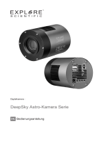 Explore Scientific Deep Sky Astro Camera 7.1MP Bedienungsanleitung
-
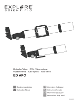 Explore Scientific ED APO 102mm f/7 Alu FCD-100 Alu HEX Bedienungsanleitung
-
 Explore Scientific 0116925 Bedienungsanleitung
-
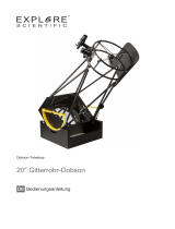 Explore Scientific Ultra Light 20'' Dobson 500mm f/3.6 GENERATION II Bedienungsanleitung
-
 Explore Scientific 0721010 Bedienungsanleitung


