
Bedienungsanleitung
Operation Manual
Innovation,
die bewegt!
4174
H0 Hebelspannwerk,
einzeln
H0 Tensioning lever,
single
1. Wichtige Hinweise / Important information ........................................................ 2
2. Einbau / Mounting ............................................................................................. 2

2
DE EN
1. Wichtige Hinweise
Bitte lesen Sie vor der ersten Anwendung des Produktes
bzw. dessen Einbau diese Bedienungsanleitung auf-
merksam durch. Bewahren Sie diese auf, sie ist Teil des
Produktes.
1.1 Sicherheitshinweise
Vorsicht:
Verletzungsgefahr!
Aufgrund der detaillierten Abbildung des Originals bzw.
der vorgesehenen Verwendung kann das Produkt Spit-
zen, Kanten und abbruchgefährdete Teile aufweisen. Für
die Montage sind Werkzeuge nötig.
1.2 Das Produkt richtig verwenden
Dieses Produkt ist bestimmt:
- Zum Einbau in Modelleisenbahnanlagen und Dioramen.
- Zum Anschluss an einen Modellbahntransformator
(z. B. Art. 5200) bzw. an eine Modellbahnsteuerung mit
zugelassener Betriebsspannung.
- Zum Betrieb in trockenen Räumen.
Jeder darüber hinausgehende Gebrauch gilt als nicht be-
stimmungsgemäß. Für daraus resultierende Schäden haftet
der Hersteller nicht.
1.3 Packungsinhalt überprüfen
Kontrollieren Sie den Lieferumfang auf Vollständigkeit:
- Hebelspannwerk, einzeln
- Anleitung
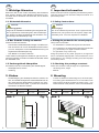
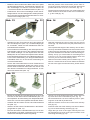
2. Einbau
- Zur Befestigung des Hebelspannwerkes müssen die
drei dem Artikel beiliegenden Kunststoffaufnahmen an
den nebenstehend abgebildeten Positionen am Turm-
mast montiert werden (Abb. 1). Maße der Positionen
entnehmen Sie bitte der Tabelle.
Spur Pos. 1 Pos. 2 Pos. 3
H0 16,9 mm 75,7 mm 87,7 mm
1. Important information
Please read this manual completely and attentively before
using the product for the first time. Keep this manual. It is
part of the product.
1.1 Safety instructions
Caution:
Risk of injury!
Due to the detailed reproduction of the original and the
intended use, this product can have peaks, edges and
breakable parts. Tools are required for installation.
1.2 Using the product for its correct purpose
This product is intended:
- For installation in model train layouts and dioramas.
- For connection to an authorized model train transformer
(e. g. item 5200) or a digital command station.
- For operation in dry rooms only.
Using the product for any other purpose is not approved
and is considered inappropriate. The manufacturer is not
responsible for any damage resulting from the improper
use of this product.
1.3 Checking the package contents
Check the contents of the package for completeness:
- Tensioning lever, single
- Manual
2. Mounting
- In order to fasten the tensioning lever, the three plas-
tic locating parts attached have to be mounted to the
tower mast to the three positions as shown in fig. 1. For
measurements of the positions, refer to the table below.
Gauge Pos. 1 Pos. 2 Pos. 3
H0 16.9 mm 75.7 mm 87.7 mm
Abb. 1 Abb. 2
Fig. 1 Fig. 2
Pos. 2
Pos. 3
Pos. 1
Kerbe 1
Kerbe 2
Kerbe 3
Kerbe 4
Kerbe 5
ungekürzt

3
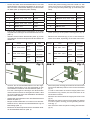
- Kürzen Sie dazu die Kunststoffaufnahmen mit Hilfe
eines Messers oder Seitenschneiders an der Nut, die
dem von Ihnen verwendeten Masttyp und der Position
am Mast (Abb. 2) entspricht (siehe Tabelle).
Kerbe Artikel Position
1H0 Art. 4115, 4160, 4162 oben
2H0 Art. 4115, 4160, 4162 unten
3H0 Art. 4116, 4161, 4163 oben
4H0 Art. 4116, 4161, 4163, unten
5H0 Art. 4117 oben
ungekürzt H0 Art. 4117 unten
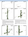
- Führen Sie die beiliegenden Drahtstücke in die dafür
vorgesehenen Öffnungen der Kunststoffaufnahmen ein
(Abb. 3).
- Winkeln Sie die beiden Drahtenden (Abb. 4) je nach
verwendetem Turmmast entsprechend den Maßen der
Tabelle ab.
Spur Artikel Position Maß
H0
4115, 4160, 4162 oben 7,0 mm
unten 9,0 mm
4116, 4161, 4163 oben 10,0 mm
unten 14,0 mm
4117 oben 13,0 mm
unten 18,0 mm
Abb. 3 Abb. 4
Fig. 3 Fig. 4
Maß
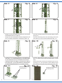
- Stecken Sie die Kunststoffaufnahme mit den abge-
winkelten Drahtenden voran wie dargestellt an den
verschiedenen Positionen auf den Mast auf (Abb. 5).
Für das nachfolgende Umbiegen der Drahtenden
müssen diese zunächst so weit gekürzt werden, dass
sie ohne Probleme hinter das Winkelblech des Mastes
geführt werden können.
- Winkeln Sie die Drahtenden hinter dem Winkelblech des
Mastes ab (Abb. 6).
- Biegen Sie die Drahtenden von hinten so um das Win-
kelblech herum, dass die Kunststoffaufnahme eng am
Mast anliegt (Abb. 7).
- Montieren Sie dementsprechend auch die beiden ande-
ren Kunststoffaufnahmenm (Abb. 8).
- Shorten the plastic locating parts with a knife or a side
cutter at the notch corresponding to the type of mast
you are using and the position (fig. 2) at the mast (see
table).
Notch Item Position
1H0 items 4115, 4160, 4162 top
2H0 items 4115, 4160, 4162 bottom
3H0 items 4116, 4161, 4163 top
4H0 items 4116, 4161, 4163, bottom
5H0 item 4117 top
unshortened H0 item 4117 bottom
- Insert the attached wire pieces into the desig-
nated openings of the plastic locating parts (fig. 3).
- Bend the two wire ends (fig. 4) acc. to the measure-
ments of the table, depending on the tower mast used.
Gauge Item Position Dimension
H0
4115, 4160, 4162 top 7.0 mm
bottom 9.0 mm
4116, 4161, 4163 top 10.0 mm
bottom 14.0 mm
4117 top 13.0 mm
bottom 18.0 mm
- Mount the plastic locating parts with the bent wire ends
first onto the different positions of the mast as illustrated
(fig. 5).
In order to bend them around the angle plate of the
mast without any problem, the wire ends have to be
shortened as needed.
- Bend the wire ends behind the angle plate of the mast
(fig. 6)
- Bend the wire ends around the angle plate from behind
so that the plastic locating part is tight-fitting with the
mast (fig. 7)
- Now mount the other two plastic locating parts likewise
(fig. 8).

4
Befestigungsbohrung
Fastening bore
Positionierungsbohrung
Positioning bore
Abb. 11 Abb. 12
Fig. 11 Fig. 12
Abb. 5 Abb. 6
Fig. 5 Fig. 6
Abb. 7 Abb. 8
Fig. 7 Fig. 8
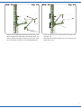
- Hängen Sie den Befestigungswinkel an der unteren
Kunststoffaufnahme ein (Abb. 9).
- Hängen Sie das Hebelspannwerk wie dargestellt in die
zuvor montierten Aufnahmen am Mast ein (Abb. 10).
Abb. 9 Abb. 10
Fig. 9 Fig. 10
- Schieben Sie den Turmmast vorsichtig vom Grundträger he-
runter (Abb. 11). Um Beschädigungen zu vermeiden sollten
Sie den Metallmast dazu am Kunststoffsockel anfassen.
- Positionieren Sie den Grundträger an der gewünschten Stelle auf
Ihrer Anlage (Abb. 12). Der richtige Abstand zur Gleismitte kann
mit Hilfe der Mastpositionslehre Art. 4197, bestimmt werden.
- Hook the mounting bracket into the lower plastic locating
part (fig. 9).
- Hook the tensioning lever into the locating parts at the
mast which you have mounted beforehand (fig. 10).
- Carefully slide down the mast from the ground socket
(fig. 11). Please touch only the plastic base, not the
mast.
- Place the ground socket at the desired spot on your
layout (fig. 12). You can find the correct distance to the
track centre by using the mast position gauge item 4197.

5
- Markieren Sie mit Hilfe eines Stiftes oder einer Spitze
die Schraubenpositionen. Anschließend entfernen Sie
den Grundträger und bohren mit einem Bohrer mit
1,2 mm Durchmesser die ermittelte Position vor (Abb. 13).
- Positionieren Sie nun den Grundträger erneut und be-
festigen diesen mit den beiliegenden Senkkopfschrau-
ben und einem Kreuzschlitz-Schraubendreher z. B. Art.
4199 auf Ihrer Anlage (Abb. 14).
Abb. 13 Abb. 14
Fig. 13 Fig. 14
- Schieben Sie den Turmmast mit der T-Nut wieder auf
den Grundträger auf (Abb. 15). Um Beschädigungen
zu vermeiden, sollten Sie den Metallmast dazu am
Kunststoffsockel anfassen.
- Die erforderliche Gesamtlänge des abzuspannenden
Fahrdrahtes ergibt sich aus dem Abstand zwischen
dem letzten Ausleger vor dem Spannwerk und dem
Mittelpunkt der am Isolator des Spannwerkes befind-
lichen Befestigungsöse plus einem Biegezuschlag von
6 mm bei der Verwendung von fertig konfektionierten
Fahrdrähten bzw. von 12 mm bei der Verwendung von
Universal-Fahrdrähten.
- Kürzen Sie anschließend den unteren Fahrdraht wie
nebenstehend dargestellt. Sollte sich in dem 42 mm
breiten Bereich zwischen dem Ende des unteren und
des oberen Fahrdrahtes ein Hänger befinden, so ent-
fernen Sie diesen bitte (Abb. 16).
Abb. 15 Abb. 16
Fig. 15 Fig. 16
- Biegen Sie mit Hilfe der Ösen-Biegezange H0 Art. 4198
eine Öse an das obere Ende des Fahrdrahtes (Abb. 17).
- Wir empfehlen die Verwendung des Abspannfahrdrah-
tes H0 Art. 4144 mit seinen parallel verlaufenden Enden.
- Schieben Sie den Isolator auf das untere Fahrdraht ende
auf (Abb. 18).
- Stecken Sie das untere Fahrdrahtende in die Befesti-
gungshülse ein (Abb. 19).
- Die Öse des oberen Fahrdrahtendes wird, wie in Abb.
20 dargestellt, in die dafür vorgesehene Öse am oberen
Isolator des Hebelspannwerkes eingehängt.
42 mm
- Mark the position of the screw with a pencil. Then re-
move the ground socket and pre-drill the determined
position with a core of ca. Ø 1.2 mm diam. (fig. 13).
- Put the ground socket back onto your model railway and
fasten it with the enclosed screws and a screwdriver,
e. g. item 4199 (fig. 14).
- Slide the mast with the t-groove back onto the ground
socket (fig. 15). Please touch only the plastic base, not
the mast.
The required total length of the catenary wire is deter-
mined by the distance between the last bracket in front
of the tensioning assembly and the central point of the
eye hook fastened to the insulator of the tensioning as-
sembly. On top you should allow for a bending bonus
of 6 mm if you use custom-made catenary wires and
12 mm if you use universal catenary wires.
- Please cut the lower catenary wire as shown in fig. 16. If
there is a vertical wire in the 42 mm wide area between
the end of the upper and the lower wire, please remove
it.
- Use the eye hook bending pliers item 4198 to bend an
eye hook at the end of the catenary wire. (fig. 17).
We recommend the use of the catenary wire for span-
ning item 4144 with its parallel ends.
- Slide the insulator onto the end of the lower catenary
wire (fig. 18).
- Insert the lower end of the catenary wire into the fasten-
ing core of the tensioning assembly (fig. 19).
- Hinge the eye hook of the upper catenary wire into
the designated eye hook at the upper insulator of the
tensioning assembly (fig. 20).

6
Abb. 17 Abb. 18
Fig. 17 Fig. 18
Abb. 19 Abb. 20
Fig. 19 Fig. 20
- Ziehen Sie den Ausleger vorsichtig aus dem Mast her-
aus (Abb. 21).
- Im Auslieferungszustand sind die Hebelspannwerke an
der linken Seite des Abspannmastes vormontiert. Möch-
ten Sie mit dem Hebelspannwerk zur anderen Seite des
Mastes abspannen, so müssen Sie die Position des
Auslegers ändern
Schieben Sie den Mast vorsichtig aus dem Grundträger,
drehen ihn um 180° und schieben ihn dann wieder auf
den Grundträger (Abb. 22).
Abb. 21 Abb. 22
Fig. 21 Fig. 22
- Carefully pull the beam out of the mast (fig. 21).
- In state of delivery the tensioning assembly is mounted
onto the left side of the mast. If you want to use the ten-
sioning assembly on the right side, you have to change
the position of the beam.
- Slide the mast carefully out of the base socket, turn it
around by 180° and slide it back onto the base socket
(fig. 22).

7
Abb. 23 Abb. 24
Fig. 23 Fig. 24
- Stecken Sie die Befestigungsstege des Auslegers in die
dafür vorgesehenen Öffnungen des Mastes (Abb. 23).
- Ziehen Sie den Ausleger vorsichtig nach unten (Abb.
24). Fassen Sie ihn dazu an den Kunststoffteilen an.
- Insert the bracket into the designated openings of the
mast (fig. 23).
- Pull down the bracket carefully (fig. 24). Hold it by the
plastic parts only.

Modellbauartikel, kein Spielzeug! Nicht geeignet für
Kinder unter 14 Jahren! Anleitung aufbewahren!
Model building item, not a toy! Not suitable for children
under the age of 14 years! Keep these instructions!
Ce n’est pas un jouet! Ne convient pas aux enfants de moi-
ns de 14 ans! Conservez cette notice d’instructions!
Não é um brinquedo! Não aconselhável para menores de
14 anos! Conservar o manual de instruções!
Modelbouwartikel, geen speelgoed! Niet geschikt voor
kinderen onder 14 jaar! Gebruiksaanwijzing bewaren!
Articolo di modellismo, non è un giocattolo! Non adatto
a bambini al di sotto dei 14 anni! Conservare istruzioni per
l’uso!
Artículo para modelismo ¡No es un juguete! No
recomendado para menores de 14 años! Conserva las
instrucciones de servicio!
DE
EN
FR
NL
IT
ES
PT
Made in Europe
Viessmann
Modelltec
hnik GmbH
Bahnhofstraße 2a
D - 35116 Hatzfeld-Reddighausen
+49 6452 9340-0
www.viessmann-modell.de
8
Änderungen vorbehalten. Keine Haftung für Druckfehler
und Irrtümer.
Die aktuelle Version der Anleitung finden Sie auf der Viess-
mann Homepage unter der Artikelnummer.
Subject to change without prior notice. No liability for
mistakes and printing errors.
You will find the latest version of the manual on the Viess-
mann website using the item number.
92056
Stand 03/sw
03/2022
Ho/Kf
Notizen Notes
-
 1
1
-
 2
2
-
 3
3
-
 4
4
-
 5
5
-
 6
6
-
 7
7
-
 8
8


in anderen Sprachen
- English: Viessmann 4174 Owner's manual
Verwandte Artikel
-
Viessmann 4164 Bedienungsanleitung
-
-
-
-
-
-
-
-
-