Viessmann 4173 Bedienungsanleitung
- Kategorie
- Kaffeezubehör
- Typ
- Bedienungsanleitung

Bedienungsanleitung
Operation Manual
Innovation,
die bewegt!
Radspannwerk, einzeln
Tensioning pulley, single
1. Wichtige Hinweise / Important information ................................................ 2
2. Einbau / Mounting ...................................................................................... 2
3. Gewährleistung / Warranty ........................................................................ 6

2
DE EN
1. Wichtige Hinweise
Bitte lesen Sie vor der ersten Anwendung des
Produktes bzw. dessen Einbau diese Bedienungs-
anleitung aufmerksam durch. Bewahren Sie diese
auf, sie ist Teil des Produktes.
1.1 Sicherheitshinweise
Vorsicht:
Verletzungsgefahr!
Aufgrund der detaillierten Abbildung des Originals
bzw. der vorgesehenen Verwendung kann das Pro-
dukt Spitzen, Kanten und abbruchgefährdete Teile
aufweisen. Für die Montage sind Werkzeuge nötig.
1.2 Das Produkt richtig verwenden
Dieses Produkt ist bestimmt:
- Zur Montage an Turmmasten, Rohrauslegern
und Quertragwerken, z. B. Art. 4115 – 4117 (H0),
4215 – 4217 (TT) oder 4315 – 4317 (N).
- Zur Verwendung in trockenen Räumen.
Jeder darüber hinausgehende Gebrauch gilt als
nicht bestimmungsgemäß. Für daraus resultierende
Schäden haftet der Hersteller nicht.
1.3 Packungsinhalt überprüfen
Kontrollieren Sie den Lieferumfang auf Vollstän-
digkeit:
- Radspannwerk, zweigeteilt
- 3 Drähte
- 3Kunststoaufnahmen
- Kunststohalterung
- 2 Isolatoren
- Anleitung
2. Einbau
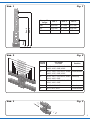
1. Zur Befestigung des Radspannwerkes müssen
diedreibeiliegendenKunststoaufnahmenan
den in Abb. 1 gekennzeichneten Positionen
montiert werden.
2. KürzenSiedieKunststoaufnahmenmitHilfe
eines Messers an der Nut, die dem von Ihnen
verwendeten Masttyp und der Position ent-
spricht (Abb. 2).
3. Führen Sie die beiliegenden Drahtstücke in die
dafürvorgesehenenÖnungenderKunststo-
aufnahmen ein (Abb. 3).
4. Winkeln Sie die beiden Drahtenden je nach
verwendetem Mast entsprechend der Tabelle
in Abb. 4 ab.
1. Important information
Please read this manual completely and attentively
before using the product for the rst time. Keep this
manual. It is part of the product.
1.1 Safety instructions
Caution:
Risk of injury!
Due to the detailed reproduction of the original
and the intended use, this product can have
peaks, edges and breakable parts. Tools are
required for installation.
1.2 Using the product for its correct purpose
This product is intended:
- For installation on headspan masts, suspended
box girders or spanbridges, e. g. items 4115 – 4117
(H0), 4215 – 4217 (TT) or 4315 – 4317 (N).
- For use in dry rooms only.
Using the product for any other purpose is not
approved and is considered inappropriate. The
manufacturer is not responsible for any damage
resulting from the improper use of this product.
1.3 Checking the package contents
Check the contents of the package for complete-
ness:
- Catenary tensioning mast, splitted
- 3 wires
- 3 plastic fasteners
- Plastic holder
- 2 insulators
- Manual
2. Mounting
1. To fasten the tensioning mast, mount the three
enclosed plastic fasteners to the marked posi-
tions (g. 1).
2. Shorten the plastic fasteners with a knife at the
groove, so that they corresponds to the type of
mast you are using and the position (g. 2).
3. Insert the supplied wire pieces into the provided
openings of the plastic fasteners (g. 3).
4. Depending on the used mast, angle the two wire
ends according to the table in g. 4.

3
Fig. 1
Abb. 1
Pos. 1
Pos. 2
Pos. 3
Spurgröße
Gauge Pos. 1 Pos. 2 Pos. 3
H0 16,9 mm 75,7 mm 87,7 mm
TT 13,2 mm 54,1 mm 62,8 mm
N 8,0 mm 42,5 mm 49,0 mm
Fig. 3
Abb. 3
Fig. 2
Abb. 2
Kerbe
Notch
für Artikel
for item Position
1
4115, 4160, 4162, 4215, 4260,
4262, 4315, 4360, 4362
oben/top
2
4115, 4160, 4162, 4215, 4260,
4262, 4315, 4360, 4362
unten/bottom
3
4116, 4161, 4163, 4216, 4261,
4316, 4361, 4363
oben/top
4
4116, 4161, 4163, 4216, 4261,
4316, 4361, 4363
unten/bottom
54117, 4217, 4317 oben/top
64117, 4217, 4317 unten/bottom
Kerbe/Notch 1
Kerbe/Notch 2
Kerbe/Notch 3
Kerbe/Notch 4
Kerbe/Notch 5
Kerbe/Notch 6

4
Fig. 5
Abb. 5
x
Fig. 4
Abb. 4
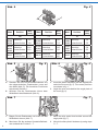
Mast Position Maß
(mm)
H0
4115
4160
4162
oben/top
unten/bottom
6,5
9,0
4116
4161
4163
oben/top
unten/bottom
10,0
12,0
4117 oben/top
unten/bottom
13,0
17,5
Mast Position Maß
(mm)
TT
4215
4260
4262
oben/top
unten/bottom
6,0
7,5
4216
4261
4263
oben/top
unten/bottom
8,5
11,0
4217 oben/top
unten/bottom
11,0
14,0
Mast Position Maß
(mm)
N
4315
4360
4362
oben/top
unten/bottom
4,0
5,5
4316
4361
4363
oben/top
unten/bottom
5,8
8,2
4317 oben/top
unten/bottom
7,4
10,4
Fig. 6
Abb. 6
Fig. 7
Abb. 7
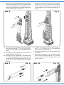
5. Stecken Sie die Kunststoffaufnahmen mit
den abgewinkelten Drahtenden voran auf
den Mast (Abb. 5). Die korrekten Positionen
entnehmen Sie Abb. 1.
6. Winkeln Sie die Drahtenden hinter dem
Winkelblech des Mastes ab (Abb. 6).
7. Biegen Sie die Drahtenden von hinten um das
Winkelblech herum (Abb. 7).
8. MontierenSiedieanderenKunststoaufnah-
men anhand der Punkte 3 – 7.
5. Insert the plastic fasteners with the angled wire
ends into the mast (g. 5). The correct positions
are shown in g. 1.
6. Angle the wire ends behind the angle plate of
the mast (g. 6).
7. Bend the wire ends from behind around the
angle plate (g. 7).
8. Mount the other plastic fasteners by using steps
3 – 7.

5
Fig. 8
Abb. 8
Fig. 9
Abb. 9 Fig. 10
Abb. 10
1
2 3
9. HängenSiedasRadspannwerkindieKunststo-
halterung ein (Abb. 8, Schritt 1). Stecken Sie es
indieKunststoaufnahmenamMast(Abb.8,
Schritt 2) und drücken es vorsichtig nach unten,
bis es einrastet (Abb. 8, Schritt 3).
10. Kürzen Sie den abzuspannenden Fahrdraht so
weit, dass er ca. H0, TT: 2 – 2,5 cm, N: 0,8 –
1,2 cm vor den Rädern des Radspannwerkes
endet.
11. Schieben Sie die Isolatoren auf die gekürzten
Fahrdrahtenden auf (Abb. 9).
12. Stecken Sie die gekürzten Fahrdrahtenden
in die Befestigungshülsen des Spannwerkes
ein (Abb. 10). Bei Bedarf können Sie die Ver-
bindung mit einem Tropfen Sekunden-kleber
xieren.
9. Mount the tensioning mast into the plastic
holder (g. 8, step 1). Insert it into the plastic
fasteners at the mast (g. 8, step 2) and push
it down slightly, until it snaps into place (g. 8,
step 3).
10. Shorten the tensioning wire so that it ends ca.
H0, TT: 2 – 2.5 cm, N: 0.8 – 1.2 cm before the
wheels of the tensioning mast.
11. Slide the insulators onto the shortened wire
ends (g. 9).
12. Insert the shortened wire ends into the mounting
sleeve of the tensioning mast (g. 10). If neces
-
sary, you can fasten the connection with a small
amount of glue.

Modellbauartikel, kein Spielzeug! Nicht geeignet für
Kinder unter 14 Jahren! Anleitung aufbewahren!
Model building item, not a toy! Not suitable for children
under the age of 14 years! Keep these instructions!
Ce n’est pas un jouet! Ne convient pas aux enfants de moi-
ns de 14 ans! Conservez cette notice d’instructions!
Não é um brinquedo! Não aconselhável para menores de
14 anos! Conservar o manual de instruções!
Modelbouwartikel, geen speelgoed! Niet geschikt voor
kinderen onder 14 jaar! Gebruiksaanwijzing bewaren!
Articolo di modellismo, non è un giocattolo! Non adatto
a bambini al di sotto dei 14 anni! Conservare istruzioni per
l’uso!
Artículo para modelismo ¡No es un juguete! No
recomendado para menores de 14 años! Conserva las
instrucciones de servicio!
DE
EN
FR
NL
IT
ES
PT
Made in Europe
Viessmann
Modelltec
hnik GmbH
Bahnhofstraße 2a
D - 35116 Hatzfeld-Reddighausen
+49 6452 9340-0
www.viessmann-modell.de
6
98940
Stand 03/sw
06/2021
Ho/Kf
3. Gewährleistung
Jeder Artikel wurde vor Auslieferung auf volle
Funktionalität geprüft. Der Gewährleistungszeitraum
beträgt 2 Jahre ab Kaufdatum. Tritt in dieser Zeit ein
FehleraufundSiendendieFehlerursachenicht,
nehmen Sie bitte Kontakt mit uns auf (service@
viessmann-modell.com). Senden Sie uns den Artikel
zur Kontrolle bzw. Reparatur bitte erst nach Rück-
sprache zu. Wird nach Überprüfung des Artikels ein
Herstell- oder Materialfehler festgestellt, wird er kos-
tenlos instandgesetzt oder ausgetauscht. Von der
Gewährleistung und Haftung ausgeschlossen sind
Beschädigungen des Artikels sowie Folgeschäden,
die durch unsachgemäße Behandlung, Nichtbeach-
ten der Bedienungsanleitung, nicht bestimmungsge-
mäßenGebrauch,eigenmächtigenEingri,bauliche
Veränderungen, Gewalteinwirkung, Überhitzung u.
ä. verursacht werden.
3. Warranty
Each model is tested as to its full functionality prior
to delivery. The warranty period is 2 years starting
on the date of purchase. Should a fault occur during
this period please contact our service department
([email protected]). Please send
the item to the Viessmann service department for
check and repair only after consultation. If we nd
a material or production fault to be the cause of the
failure, the item will be repaired free of charge or
replaced. Expressively excluded from any warranty
claims and liability are damages of the item and
consequential damages due to inappropriate han-
dling, disregarding the instructions of this manual,
inappropriate use of the model, unauthorized dis-
assembling, construction modications and use of
force, overheating and similar.
Änderungen vorbehalten. Keine Haftung für Druck-
fehler und Irrtümer.
DieaktuelleVersionderAnleitungndenSieauf
der Viessmann Homepage unter der Artikelnummer.
Subject to change without prior notice. No liability for
mistakes and printing errors.
You will nd the latest version of the manual on the
Viessmann website using the item number.
-
 1
1
-
 2
2
-
 3
3
-
 4
4
-
 5
5
-
 6
6


Viessmann 4173 Bedienungsanleitung
- Kategorie
- Kaffeezubehör
- Typ
- Bedienungsanleitung
in anderen Sprachen
- English: Viessmann 4173 Owner's manual
Verwandte Artikel
-
Viessmann 4174 Bedienungsanleitung
-
-
-
-
-
-
-
-
-