SBC In-wall-kits for 5,7"/7", 10.4" & 12.1" MB-Panels Bedienungsanleitung
- Typ
- Bedienungsanleitung

Saia-Burgess Controls AG
Bahnhofstrasse 18, 3280 Murten, Switzerland
T +41 26 580 30 00, F +41 26 580 34 99
www.saia-pcd.com
26-889_ENG-GER-FRA04_Manual-PCD7D457-IWSx_Word-2016-01-12.docx © Saia-Burgess Controls AG – January 2016
Page 1 / 12
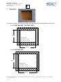
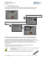
Short overview / Kurzer Überblick / Rapide vue d’ensemble
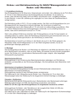
Mounting instructions for “In-wall mounting kit” for
SBC Web Panels MB 5.7”, 10.4’’ and 12.1’’.
Montageanweisung für das „Unterputzmontagekit“ des
SBC Web Panels MB Panels 5.7”, 10.4’’ und 12.1’’.
Instructions de montage pour le „kit pour montage encastré » des pupitres
SBC Web Panels MB 5.7”, 10.4’’ et 12.1’’.
E
D
F
5
4
1
2
3
6
Clic !

Saia-Burgess Controls AG
Bahnhofstrasse 18, 3280 Murten, Switzerland
T +41 26 580 30 00, F +41 26 580 34 99
www.saia-pcd.com
26-889_ENG-GER-FRA04_Manual-PCD7D457-IWSx_Word-2016-01-12.docx © Saia-Burgess Controls AG – January 2016
Page 2 / 12
The in-wall mounting kits for building the PCD7.D457-IWS2, PCD7.D410-IWS and PCD7.D412-IWS into a
solid wall or hollow wall comprises:
Quantity
Name
1
Complete built-in box (Material: steel)
1 Set
Containing:
× 4 Centring screws M4 × 30 Torx*
× 4 Plastic wall plugs D7 × L30
× 4 Pan-Head chipboard screws D5 × L35 Torx*
+ for 5.7” only:
× 1 Front plate
× 1 Adapter housing
1
Mounting instruction
The kit PCD7.D457-IWS2 is available for PCD7.D457xxxx MB panels series.
The kit PCD7.D410-IWS is available for PCD7.D410xxxx MB panels series.
The kit PCD7.D412-IWS is available for PCD7.D412xxxx MB panels series.
* Torx screwdriver is not supplied with the kit.
Die PCD7.D457-IWS2, PCD7.D410-IWS und PCD7.D412-IWS Montagesets für den Einbau in Vollwände
oder „Hohlwände“ bestehen aus:
Anzahl
Bezeichnung
1
Einbaugehäuse (Material: Stahl)
1 Set
bestehend aus:
× 4 Zentrierschrauben M4 × 30 Torx*
× 4 Kunststoffdübel D7 × L30
× 4 Pan-Head Spanplattenschrauben D5 × L35 Torx*
+ für 5.7“ nur:
× 1 Frontplatte
× 1 Adapterblech
1
Montageanweisung
Das Kit PCD7.D457-IWS2 ist gültig für PCD7.D457xxxx MB Panel Serien.
Das Kit PCD7.D410-IWS ist gültig für PCD7.D410xxxx MB Panel Serien.
Das Kit PCD7.D412-IWS ist gültig für PCD7.D412xxxx MB Panel Serien.
* Torx-Schraubendreher wird nicht mit dem Kit mitgeliefert.
Les kits pour montage encastré pour mur plein ou pour mur creux PCD7.D457-IWS2, PCD7.D410-IWS et
PCD7.D412-IWS se composent de :
Quantité
Désignation
1
Boîtier d’encastrement complet. ( Matériel : acier)
1 Set
se composant de :
× 4 Vis de centrage latéral M4 × 30 Torx*
× 4 chevilles plastique D7 × L30
× 4 vis autotaraudeuses tête cylindrique D5 × L35 Torx*
+ uniquement pour les 5.7’’ :
× 1 plaque frontale
× 1 plaque d’adaptation
1
Instructions de montage
Le kit PCD7.D457-IWS2 est valable pour la série de MB panel PCD7.D457xxxx
Le kit PCD7.D410-IWS est valable pour la série de MB panel PCD7.D410xxxx
Le kit PCD7.D412-IWS est valable pour la série de MB panel PCD7.D412xxxx
* Le tournevis Torx n’est pas livré avec le kit
D
F
E

Saia-Burgess Controls AG
Bahnhofstrasse 18, 3280 Murten, Switzerland
T +41 26 580 30 00, F +41 26 580 34 99
www.saia-pcd.com
26-889_ENG-GER-FRA04_Manual-PCD7D457-IWSx_Word-2016-01-12.docx © Saia-Burgess Controls AG – January 2016
Page 3 / 12
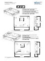
Drawing of the built-in box for the kit
PCD7.D410-IWS / D457-IWS2
Zeichnung des Einbaugehäuses für das
Kit PCD7.D410-IWS / D457-IWS2
Dessin du boîtier d’encastrement du kit
PCD7.D410-IWS / D457-IWS2
65 mm
75mm
R15
207 mm
267 mm
65 mm
75mm
R15
Dia 30mm
305 mm
251 mm
Drawing of the built-in box for the kit
PCD7.D412-IWS
Zeichnung des Einbaugehäuses für das
Kit PCD7.D412-IWS
Dessin du boîtier d’encastrement du kit
PCD7.D412-IWS
D
F
E
***************************************************************************

Saia-Burgess Controls AG
Bahnhofstrasse 18, 3280 Murten, Switzerland
T +41 26 580 30 00, F +41 26 580 34 99
www.saia-pcd.com
26-889_ENG-GER-FRA04_Manual-PCD7D457-IWSx_Word-2016-01-12.docx © Saia-Burgess Controls AG – January 2016
Page 4 / 12
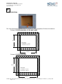
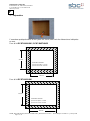
1 - Preparation
The opening made in the wall or partition-wall must have the following dimensions in mm.
For kit PCD7.D410-IWS / PCD7.D457-IWS2
For kit PCD7.D412-IWS
E
Minimum depth:
for solid wall = 75 mm
for hollow wall = 65 mm
211 mm
270 mm
309 mm
254 mm
Minimum depth:
for solid wall = 75 mm
for hollow wall = 65 mm

Saia-Burgess Controls AG
Bahnhofstrasse 18, 3280 Murten, Switzerland
T +41 26 580 30 00, F +41 26 580 34 99
www.saia-pcd.com
26-889_ENG-GER-FRA04_Manual-PCD7D457-IWSx_Word-2016-01-12.docx © Saia-Burgess Controls AG – January 2016
Page 5 / 12
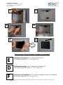
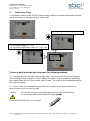
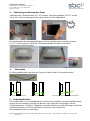
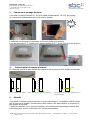
2 - Cable entry, fixing
The Ethernet cable and the 24 VDC power supply cable are normally inserted through the
top or the bottom or through the back of the case
The box is built-in into the wall using one of the following methods:
A – Screwing into the wall (left side and right side). You can choose the type of fixations
(M4 Centring screws or/and Pan-Head chipboard screws). These screws and wall plugs
are supplied with the kit. Other screws may be used. The length of the screws depends on
the support material.
B - Glue or filler in small quantity around the box (mortar, quick-drying cement etc.)
before to mount the box into the wall.
Careful: - Do not use too much expanding foam as this might distort the box.
- Do not put glue/filler round about the eight springs.
Check that the built-in box is horizontal.
× 4 Centring screws M4 × 30 Torx
×
4 Plastic wall plugs D7
×
L30
× 4 Pan-Head chipboard screws D5 × L35 Torx

Saia-Burgess Controls AG
Bahnhofstrasse 18, 3280 Murten, Switzerland
T +41 26 580 30 00, F +41 26 580 34 99
www.saia-pcd.com
26-889_ENG-GER-FRA04_Manual-PCD7D457-IWSx_Word-2016-01-12.docx © Saia-Burgess Controls AG – January 2016
Page 6 / 12
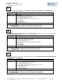
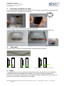
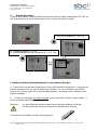
3 - Connecting, assembling the panel
Connect the Ethernet cable (RJ-45) and the 24 VDC power supply cable to the panel (the
power connector is supplied with the panel).
Put the panel in front of the box and fixe it by pressing.
For 5.7” panels, first mount those 2 parts before and fix them using the fixation set:
4 - Earth cable
An earth cable should be mounted between the panel and the wall kit.
Panel> earth cable> box Panel> protective earth cable Panel> earth cable> box> protective earth cable
5 - Safety
This product must not be connected to a domestic mains supply. It must be installed by
qualified personnel (knowledge of standards, current rules and safety regulations).
Any work on this product (assembly, connecting and disassembling) must be carried out
whilst not connected to a domestic mains supply.
Clip !

Saia-Burgess Controls AG
Bahnhofstrasse 18, 3280 Murten, Switzerland
T +41 26 580 30 00, F +41 26 580 34 99
www.saia-pcd.com
26-889_ENG-GER-FRA04_Manual-PCD7D457-IWSx_Word-2016-01-12.docx © Saia-Burgess Controls AG – January 2016
Page 7 / 12
1 - Vorbereitung
Die vorzunehmende Wandaussparung hat die in mm angegebene Grösse vorzuweisen
Für das Kit PCD7.D410-IWS / PCD7.D457-IWS2
Für das Kit PCD7.D412-IWS
Mindesttiefe:
für Vollwand = 75 mm
für Hohlwand = 65 mm
211 mm
270 mm
309 mm
254 mm
Mindesttiefe:
für Vollwand = 75 mm
für Hohlwand = 65 mm
D

Saia-Burgess Controls AG
Bahnhofstrasse 18, 3280 Murten, Switzerland
T +41 26 580 30 00, F +41 26 580 34 99
www.saia-pcd.com
26-889_ENG-GER-FRA04_Manual-PCD7D457-IWSx_Word-2016-01-12.docx © Saia-Burgess Controls AG – January 2016
Page 8 / 12
2 - Kabeleinführung, Fixierung
Das Ethernet-Kommunikationskabel sowie das 24 VDC Versorgungskabel werden
normalerweise durch die Ober-, Unter- oder Rückseite des Gehäuses eingeführt.
Die Anbringung des Einbaugehäuses in der Wand erfolgt folgendermaßen:
A- Fixierung durch Verschraubung in die Wand (rechts oder links). Die Typen der
Schrauben (M4 Zentrierschrauben oder/und Pan-Head Spanplattenschrauben) können
beliebig sein. Diese Schrauben und Dübel werden mit dem Kit mitgeliefert.
Andere Schrauben können benutzt werden. Die Länge der Schrauben hängt vom
Hilfsmaterial ab.
B- Auffüllen oder Abdichten des Gehäuses mit geringen Mengen Mörtel,
schnellabbindendem Zement oder Ähnlichem.
Achtung: - Bitte verwenden Sie keinen Bauschaum. Dies könnte zur Verformung des
Gehäuses führen.
- Setzen Sie keinen Mörtel, Zement direkt an die acht Federn.
Achten Sie darauf, dass das Einbaugehäuse waagrecht angebracht ist.
x 4 Zentrierschrauben M4 x 30 Torx
×
4 Kunststoffdübel D7
×
L30
×
4 Pan-Head Spanplattenschrauben D5
×
L35 Torx

Saia-Burgess Controls AG
Bahnhofstrasse 18, 3280 Murten, Switzerland
T +41 26 580 30 00, F +41 26 580 34 99
www.saia-pcd.com
26-889_ENG-GER-FRA04_Manual-PCD7D457-IWSx_Word-2016-01-12.docx © Saia-Burgess Controls AG – January 2016
Page 9 / 12
3 - Verbindung und Montage des Panel.
Verbinden des Ethernet-Kabels (RJ-45) und des Versorgungskabels 24 VDC an das
Panel (der Stromversorgungsstecker wird mit dem Panel mitgeliefert).
Das Bedienpanel korrekt gegenüber dem Gehäuse positionieren und dann pressen.
Für 5.7” Panels müssen zuerst die 2 Befestigungsteile montiert und mit dem
Befestigungsset fixiert werden.
4 - Massekabel
Ein Massekabel sollte zwischen das Panel und dem Einbau Kit montiert werden.
Panel> Massekabel> Gehäuse Panel> Schutzerdekabel Panel> Massekabel> Gehäuse> Schutzerdekabel
5 - Sicherheitshinweise
Das Produkt darf nur von qualifiziertem Personal an das elektrische Hausinstallationsnetz
angeschlossen werden (Kenntnis der Normen, der geltenden Vorschriften und der
Sicherheitsregeln). Sämtliche Tätigkeiten mit und an diesem Produkt (Montage, Anschluss
und Abmontierung) sind ohne jeglichen Anschluss an das elektrische
Hausinstallationsnetz vorzunehmen.
Clip !

Saia-Burgess Controls AG
Bahnhofstrasse 18, 3280 Murten, Switzerland
T +41 26 580 30 00, F +41 26 580 34 99
www.saia-pcd.com
26-889_ENG-GER-FRA04_Manual-PCD7D457-IWSx_Word-2016-01-12.docx © Saia-Burgess Controls AG – January 2016
Page 10 / 12
1 - Préparation
L’ouverture pratiquée dans le mur (plein ou creux) doit avoir les dimensions indiquées
en mm.
Pour le kit PCD7.D410-IWS / PCD7.D457-IWS2
Pour le kit PCD7.D412-IWS
F
Profondeur minimum:
pour un mur plein = 75 mm
pour un mur creux = 65 mm
211 mm
270 mm
309 mm
254 mm
Profondeur minimum:
pour un mur plein = 75 mm
pour un mur creux = 65 mm

Saia-Burgess Controls AG
Bahnhofstrasse 18, 3280 Murten, Switzerland
T +41 26 580 30 00, F +41 26 580 34 99
www.saia-pcd.com
26-889_ENG-GER-FRA04_Manual-PCD7D457-IWSx_Word-2016-01-12.docx © Saia-Burgess Controls AG – January 2016
Page 11 / 12
2 - Arrivée des câbles
L’arrivée du câble de communication Ethernet ainsi que le câble d’alimentation 24 VDC se
fait normalement soit par le haut soit par le bas ou par le fond de la cavité.
La tenue du boîtier d’encastrement dans le mur peut se faire par:
A - Fixation par vissage dans l’épaisseur du mur (côté droit et côté gauche). La type de vis
(vis de centrage ou/et vis auto-taraudeuses) est libre. Ces vis et chevilles sont livrées
avec le kit. D’autres types de vis peuvent être utilisées. La longueur des vis dépende du
type de matériau.
B - Collage ou bourrage, en petite quantité, autour du boîtier (mortier, ciment rapide …)
avant le montage du boîtier dans le mur.
Attention: - ne pas utiliser de mousse expansive qui pourrait déformer le boîtier.
- Ne pas mettre de mortier ou ciment à proximité des 8 ressorts
Contrôler l’horizontalité du boîtier d’encastrement
× 4 Vis de centrage M4 × 30 Torx
×
4 Chevilles plastque D7
×
L30
×
4 vis autotaraudeuses tête cylindrique D5
×
L35 Torx

Saia-Burgess Controls AG
Bahnhofstrasse 18, 3280 Murten, Switzerland
T +41 26 580 30 00, F +41 26 580 34 99
www.saia-pcd.com
26-889_ENG-GER-FRA04_Manual-PCD7D457-IWSx_Word-2016-01-12.docx © Saia-Burgess Controls AG – January 2016
Page 12 / 12
3 - Connexion et montage du panel.
Connecter le câble Ethernet (RJ-45) et le câble d’alimentation. 24 VDC au pupitre.
(le connecteur d’alimentation est livré avec le pupitre)
Positionner correctement le panneau en face du boîtier puis presser.
Pour les panneaux 5.7”, monter les 2 pièces dédiés au 5.7’’ et les fixer avec les fixations.
4 - Cable de mise à la masse (à la terre):
Un câble de mise à la terre devrait être monté entre le panneau et le boîtier encastrable.
Panel> câble de terre> boîtier Panel> câble de mise à la terre de protection Panel> cable de terre> boîtier> câble de mise à la
terre de protection
6 - Sécurité
Ce produit ne doit pas être connecté au secteur domestique. L’installation doit être faite
par du personnel qualifié. (Connaissance des normes, des prescriptions en vigueurs et
des règles de sécurité)
Toutes les activités sur ce produit (montage, raccordement et démontage) doivent être
exécutées sans aucune connections au secteur domestique.
Clip !
-
 1
1
-
 2
2
-
 3
3
-
 4
4
-
 5
5
-
 6
6
-
 7
7
-
 8
8
-
 9
9
-
 10
10
-
 11
11
-
 12
12


SBC In-wall-kits for 5,7"/7", 10.4" & 12.1" MB-Panels Bedienungsanleitung
- Typ
- Bedienungsanleitung
in anderen Sprachen
Verwandte Artikel
-
SBC On-wall-kit for 5,7"/7", 10.4" & 12.1" MB-Panels Bedienungsanleitung
-
-
-
-
-
-
-
-
-