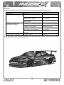
HPI Racing Maverick Strada Benutzerhandbuch
- Kategorie
- Ferngesteuertes Spielzeug
- Typ
- Benutzerhandbuch

HOBBY PRODUCTS INTERNATIONAL EUROPE LTD.
19 WILLIAM NADIN WAY
SWADLINCOTE, DERBYSHIRE, DE11 OBB, UK
HPI RACING LTD.
19 WILLIAM NADIN WAY
SWADLINCOTE, DERBYSHIRE, DE11 OBB, UK
Tel: +44 (0)1283 226570
WWW.MAVERICK-RC.COM
English ..............02
Deutsch ..............15
Français ..............28
Español ..............41
MV29995

2
HAVE FUN! But please read this fi rst !!
We know you will have great fun with your model, but to get the best from your purchase please read this information
BEFORE you operate the model.
Table of contents
Page
Warranty 2
Safety Precautions 3
Components 3
Tools 3
Items required for operation 4
Charging the battery pack 4
Installing the batteriers 4
Transmitter 5
Trim Setup 5
Turning on the power 6
Turning off the power 6
Electronic Speed Control Setup 7
Driving 13
Maintenance after driving 13
Trouble Shooting 14
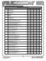
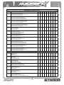
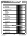
Parts List 54
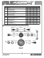
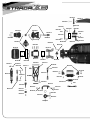
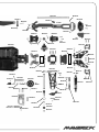
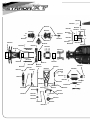
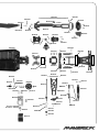
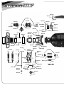
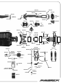
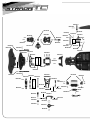
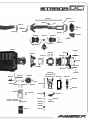
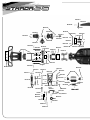
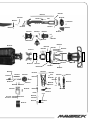
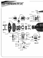
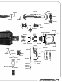
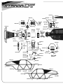
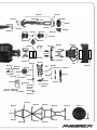
Exploded Views 65
90 Day Component Warranty
We want you to enjoy your purchase, but please read this fi rst!
This product is covered by a 90 day component warranty from date of purchase. If any part of the product fails as a
result of faulty manufacture during this period then we will repair or replace that part at our discretion.
We do not operate a new for old warranty once the product has been used.
Please note this product is not a toy and it is recommended that children 14 and under are supervised by an adult. It is
the responsibility of the parent or guardian to ensure minors are given appropriate guidance and supervision.
If you suspect there is a problem with the product, for whatever reason, it is the user’s responsibility to investigate and
take steps to rectify the problem before further damage occurs.
Not Covered By Warranty
This is a sophisticated, high performance model and should be treated with care and respect. Every effort has been
made to make this product as strong and durable as possible, however due to the nature of this product, it is still
possible to break or damage parts through crashing or extreme use. Components damaged as a result of crash
damage, improper use, lack of maintenance or abuse are not covered by the warranty.
How to Claim Against your Warranty
For warranty claims please fi rst contact your supplying retailer. Do not return the product to your distributor without
their prior approval. You may not need to return the product in full, only the damaged component along with a copy of
your purchase receipt. In many cases it is faster and more cost effective for the user to fi t the replacement part(s) to
the product & therefore we reserve the right to supply parts only in these instances.
Any returned component that is inspected by your distributor and found to have an invalid warranty claim may be
subject to an inspection and handling fee before it can be returned. Any repairs required as a result of neglect or
misuse will be charged before any work is carried out on the product. If you decide not to have any work carried out
the distributor reserves the right to charge a handling and a shipping fee.
Please attach your proof of purchase in the manual as you may need it again in the future.

3
Safety precautions
This product is an authentic radio controlled vehicle (RC vehicle) and it is not a toy. Read and understand this
instruction manual thoroughly before running the model. If you are not familiar with RC vehicles, we recommend that
you ask someone familiar with RC vehicles for advice.
Never connect the rechargeable drive battery in the reverse polarity or disassemble the battery. If the drive battery is
used in the wrong way, high current can be generated and it is very dangerous.
Never run RC models near people or animals, or on public streets or highways. This could cause serious accidents,
personal injuries, and/or property damage.
Make sure the mains power socket when using a charger is readily accessible and never left plugged in when not in
use.
If you are using Rechargeable AA’s for the Transmitter please make sure you also purchase a suitable charger for this
battery type.
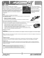
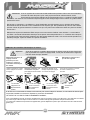
DISCONNECT THE BATTERY
PACK AFTER USE!
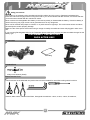
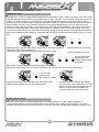
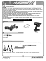
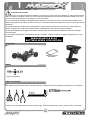
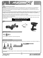
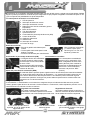
Transmitter
Parts Bag
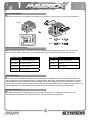
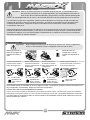
Components
5.5
mm
7
mm
1. 5
mm
2.0
mm
2.5
mm
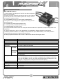
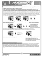
Included Tools
These tools are not included with the product but are recommended for use whilst working with this vehicle
Scissors, Side Cutters, Needle Nose Pliers, Hexagonal Screwdrivers 1.5mm, 2.0mm, 2.5mm, Screwdriver,
Recommended Tools
4-Way Cross Wrench (Small)

4
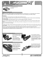
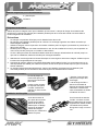
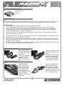
4 * AA Batteries for the
Transmitter
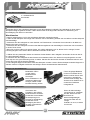
Items required for operation
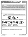
Charging the battery pack
Always use the included charger for the included battery pack. Charging time for an empty battery pack is about 6
hours. Do not charge the battery pack longer than 6 hours to avoid overheating and battery damage.
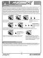
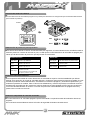
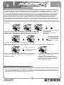
Installing the Transmitter Batteries
Open the battery holding
tray to expose the empty
battery slots.
Insert 4 AA batteries
into the marked spaces.
Please note the correct
direction of the batteries
Incorrect battery insertion
could damage the transmitter
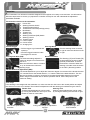
2.4Ghz technology has done
away with the need for long
extendable aerials. The Aerial
on your transmitter is located
internally
Installing the battery pack
You need to insert the
battery pack in the open
section for the battery.
Use the chassis cut-out
for corner wiring if
needed. Use the straps
provided to secure the
battery in place.
Once fastened and secured
please connect the battery
plug into the speed controller
plug noting correct polarity.
Red to red, black to black.
1
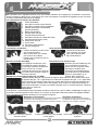
Cautions
• This charger can be used only for the battery pack included in this kit.
• Do not charge the battery pack for longer than 6 hours. Overcharging generates excessive heat and will damage
the battery pack.
• Use the charger with adult supervision. Do not use the charger near water or when wet.
• Do not use the charger if the wire is frayed or worn. If the wire is frayed or worn a short circuit can cause a fi re or
burns.
• If you are not sure about the level of the battery pack before charging use it in the vehicle until the vehicle slows,
leave to cool and then recharge.
1. Select your regions electrical mains plug and attach it to the charger. Always use the correct mains plug version for
your country.
2. Connect the charging socket to the supplied battery packs power plug. The connectors are sided and have a clip to
secure it in place. Do not force together and always check you have the connection the right way round.
3. The charger will automatically start to charge your battery pack. Do not leave connected for more than 6 hours on
a fl at battery pack and always observe the cautions above.

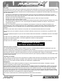
5
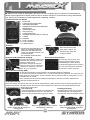
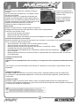
Throttle Trigger
1. Power LED
2. Steering Reverse Switch
3. Throttle Reverse Switch
4. Throttle End Point Dial (low/high points)
5. Bind Button
6. Throttle Trim
7. Steering Trim
8. Steering Dual Rate (D/R) Switch
9. Steering Control
10. Throttle Trigger
11. P.P.M. Output
12. Power Switch
13. Charging Port
• Pull the trigger to go forwards and
speed up
• Push the trigger forward to brake
• Push again for reverse
Turn the steering wheel to the left
or right to make the vehicle turn left
or right
The Steering (ST) and Throttle (TH)
reverse switches are set to “NOR”
(Normal) as standard. To switch
the direction of travel of either the
steering or throttle move the switch
to the “REV” (Reverse) position.
The dual rate settings adjust the
maximum degree of movement from
the servo.
Move the D/R lever down to increase
or up to decrease the maximum
steering angle.
Transmitter
Your Transmitter is an advanced controller designed for the beginner to be easy to use and tune. You will need to
follow the steps below to ensure you prepare the controller correctly for use and understand the adjustment
possibilities available.
The function switches on the transmitter
12
13
Steering Wheel
Steering Dual Rate (D/R) Reverse Switches
Trim Setup
If the steering is not straight with the transmitter on, make sure the trim dial is set to the central position and adjust
the Servo horn on the car if needed. Then make fi ne adjustments with the steering trim whilst driving the vehicle.
Throttle Trim
Throttle neutral adjustments can be made
by moving the throttle trim lever up for more
throttle or down for more brake.
Steering Trim
Steering neutral adjustments can be made
by moving the steering trim lever left or right.
If the wheels point left, turn
clockwise
If wheels point right, turn
anti-clockwise.
If they point straight no adjustment
required.
Throttle End Point Adjustment (EPA)
The throttle EPA allows you to adjust the maximum degree of movement of the throttle channel.
“Hi” sets the EPA for the throttle direction, “Lo” sets the EPA for the brake direction. Turn the
dial anti-clockwise to reduce or clockwise to increase the allowable degree of movement.
When using this transmitter with an electric powered vehicle, set the end points to the
maximum setting.
11

6
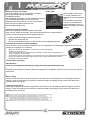
Turning on the power
Turn on transmitter fi rst and then turn on receiver.
Turn on the transmitter switch and the LED battery
indicator will light up.
Turn on the receiver. The automatic set-up of the factory
set speed control should have been completed. If you
experience any problems with the speed control settings
refer to the Electronic Speed Control Section for correct
setup information.
The Red LED will show if the
installed AA batteries have
suffi cient charge.
The Red LED will fl ash and
there will be an audible beep if
the batteries need replacing.
Power LED
You may need to setup your transmitter to ‘bind’ with the receiver if you change to a new receiver or for any reason
lose signal.
• Place the transmitter and the receiver close to each other (within one meter).
• Turn the power switch on the transmitter to the ON position.
• Press and hold the receiver setup button, then turn the power switch to the ON position.
• The receiver LED will fl ash quickly. Release the setup button after 1 second.
• Press and hold the binding button on the transmitter for 1 second until the LED on the
receiver is continuously lit.
Binding the Transmitter and Receiver
1
Turning off the power
Turn off receiver fi rst and then turn off transmitter.
If you switch off the transmitter fi rst before the R/C car, you may lose control of the R/C car.
• Turn off the receiver switch.
• Turn off the transmitter switch.
• Disconnect the battery connector from the speed control connector.
Fail Safe Setup
Caution
Any new binding of transmitter & receiver will clear the pre-set fail safe.
1.
With the transmitter and car switched on, press the setup button on the receiver then release. LED will fl ash.
2.
Electric setup
Leave throttle trigger in neutral position, and press the setup button. The LED will fl ash quickly. Once the receiver
LED remains lit, then release the setup button on the receiver.
Nitro setup
Hold full brake on the transmitter, and press the setup button. The LED will fl ash quickly. Release full brake on the
transmitter once the receiver LED remains lit, then release the setup button on the receiver.

7
Always disconnect the battery from the speed controller after driving.
Never connect the speed controller incorrectly or with reversed polarity.
Wrong connection or reversed polarity will damage the speed controller.
Please use an optional capacitor with the motor for good frequency reception.
Do not use a motor under 12T when using 2S Lipo or 6 sells NiMH (Example: 11T,10T, 9T and lower turn motors),
Using a lower turn motor may damage the speed controller. (Although your motor may be in the safe range,
your ESC may go into overheat protection mode due to your choice of gearing or track conditions (off-road, high
traction, etc.))
Do not use a motor under 18T when using 3S Lipo or 9 sells NiMH (Example: 17T,16T, 15T and lower turn
motors), Using a lower turn motor may damage the speed controller. (Although your motor may be in the safe
range, your ESC may go into overheat protection mode due to your choice of gearing or track conditions (off-road,
high traction, etc.))
After running in water, dry off any excess water from ESC and connectors.
During and after running, your speed controller will become hot. Do not touch the heatsink your with bare hands
otherwise, they will get burned.
The speed control has 2 types of battery modes to choose from depending on which type of battery you use
(NiMH and LiPo). Setup for the proper battery is needed. If you do not setup your speed control correctly, your
battery may explode, swell, smoke, or become useless.
Caution
Failure to follow these instructions can cause injury to yourself or others. You might also
cause property damage or damage your kit.
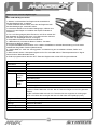
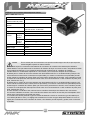
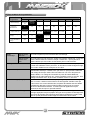
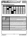
Electronic Speed Control Setup
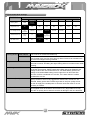
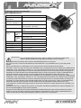
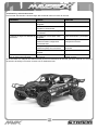
MSC-30BR-WP Features:
Model MSC-30BR-WP
FWD Continuous / Burst
Current
40A / 180A
REV Continuous / Burst
Current
20A / 90A
Resistance FWD: 0.002 Ohm; REV: 0.004 Ohm;
Application 1/10 scale On-Road and Off-Road
Motor Limit 2S LiPo /
6 cell NiMh
540 or 550 size motor ≥ 12T
RPM < 30000 @7.2V
3S LiPo /
9 cell NiMh
540 or 550 size motor ≥ 18T
RPM < 20000 @7.2V
Battery 5-9 cells NiMh or 2-3S LiPo
Built-in BEC 6V/2A
PWM Frequency 1KHz
Dimension 46.5x34x28.5mm
Weight 65g

8
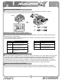
ON OFF
REV
BATT
LiPo NiMH
LiP
o
Ni-M
H
Beep Sound
1 Short Beep The battery is NiMH/NiCd
2 Short Beep The battery is 2S LiPo
3 Short Beep The battery is 3S LiPo
1 Long Beep
Self-test and throttle calibration is okay.
The ESC is ready to run
Choose Battery Mode
The ESC is programmed with the use of jumpers to select setting. (Tweezers are recommended to plug in the jumpers)
If the voltage of the battery pack is lower than the threshold for 2 second, the ESC will enter the protection mode.
When the car stops, the red LED blanks on the ESC to indicate that the low voltage cut-off protection has been
activated.
LED Status
LED is off When the throttle trigger is in neutral range
LED blinks Forward, brake or reverse at partial throttle
LED is solid Forward, brake or reverse at full throttle
Low voltage cut-off protection
When the interval temperature of the ESC is higher than a factory preset threshold for 5 seconds, the ESC will
reduce and will cut off the output power.
Once the Overheat Protection is activated, the throttle repeats turning on and off quickly and acceleration becomes
erratic. Stop driving immediately and solve the problem by referring to the Troubleshooting guide. Do not drive the
R/C car until the LED turns off. Allow the Speed Controller to cool down for 15 minutes.
The Overheat Protection function will turn off and you can drive the R/C car again.
The ESC will cut off the output power if the throttle signal has been lost for 0.1 second.
The “Fail Save“ function of the radio system is strongly recommended to be activated.
Overheat Protection
Throttle signal loss protection
Jumper

9
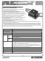
Electronic Speed Control Setup
MSC-30BL-WP Features:
1. Water-resistant* and dust-proof. The ESC has been designed to
work in wet conditions.
a.*Please remove the cooling fan when using the ESC very wet conditions.
b.*After using the ESC in wet conditions, please clean and dry it to avoid
the oxidation to copper connectors
2. 2-3S Capalable (for 3S you must change the standard 5V
cooling fan to a 12V cooling fan, or supply the 5V cooling fan from
the receiver 5-6V);
3. Compatible with sensorless brushless motor.
4. 2 running modes (“Forward with brake” mode,
“Forward/Backward with brake” mode).
5. Proportional ABS brake function with 4 steps of maximum brake force adjustment, 8 steps of drag-brake force
adjustment.
6. 4 Punch modes from “Soft” to “Very aggressive” to be suitable for different chassis, tires and tracks.
7. Multiple protection features: Low voltage cut-off protection for Lipo or NiMH battery / Over-heat protection /
Throttle signal loss protection / Motor blocked protection.
8. Easily programmed with the “SET” button on the ESC or with the LED Program Card.
Model MSC-30BL-WP
Continuous Current 45A
Burst Current 220A
Resistance 0.0012 ohm
Application 1/10 scale On-Road and Off-Road
Motor Limit 2S LiPo /
6 cell NiMh
On-Road: ≥ 9T
Off-Road: ≤ 12T
3650 Size Motor
3S LiPo /
9 cell NiMh
On-Road: ≥ 12T
Off-Road: ≤ 18T
3650 Size Motor
Battery 4-9 cells NiMh or 2-3S LiPo
1) For 4-6 cells NiMH or 2S Lipo: You needn’t change the 5V cooling fan on the ESC;
2) For 7-9 cells NiMH or 3S Lipo: You must change the original 5Vcooling fan to 12V
cooling fan, or supply the 5V cooling fan from the receiver (5-6V);
Built-in BEC 6V/2A
Program Port Multiplexed with cooling fan port
Motor Type Sensorless Brushless
Dimension 48.5*38*32mm
Weight 90g

10
You must set up the ESC before running the fi rst time. Initial setup, it is not required
before every run.
Important !
Hold down the setup
button while turning on
the ESC.
Release the setup button
once the Red LED starts to
fl ash
LED LED
Leave the trigger in the
neutral position.
Press the setup button.
Move the trigger to full
throttle.
Press the setup button.
Move the trigger to full
brake.
Press the setup button.
When the process has
fi nished, motor control will be
activated in 3 seconds
LED LED
LED LED
LED LED
LED LED
Green LED
fl ashes and a
Beep sound
comes from the
motor.
Green LED
fl ashes twice.
Beeps twice from
the motor.
Green LED
fl ashes three
times. Beeps
three times from
the motor.
No LED Lighting
If the LED on the speed control does not work as described below, the speed control may not be setup correctly. Repeat the
above process.
THE LED STATUS IN NORMAL RUNNING:
a) In normal use, if the throttle stick is in the neutral range,neither the red nor green LED will light.
b) The red LED lights when the car is run forward or backwards and will fl ash quickly when the car is braking.
c) The green LED lights when the throttle stick is moved to the top point of the forward zone (full throttle).
This is an extremely powerful brushless motor system. We strongly recommend removing
your tyres for your own safety and the safety of those around you before performing
calibration and programming functions with this system. Please keep your hands, hair, and
loose clothing clear from the gear train and wheels of an armed high performance system.
Rubber tyres will “expand” to extreme size on a high speed vehicle. DO NOT hold the vehicle in the air and run
it up to full throttle. Tyre failures at that speed can cause serious injury! Make sure your tires are securely glued
to the rims and check them often! Always disconnect the battery from the ESC when you are fi nished using your
vehicle.
The switch on the ESC controls the power that is delivered to the receiver and servos. The controller will always
draw current when it is connected to the battery and will completely discharge batteries if they are connected or
long durations. This may cause failure of your batteries.
Caution
ESC Setup

11
Programmable Mode Settings
PROGRAM
PROGRAMMABLE VALUE
1 2 3 4 5 6 7 8
1. Running Mode
Forward with
Brake
Forward/
Reverse
with Brake
2. Drag Brake Force 0% 5% 10% 15% 20% 25% 30% 40%
3. Low Voltage Cut-off
Non-
Protection
2.6V/cell 2.8V/cell 3.0V/cell 3.2V/cell 3.4V/cell
4. Start Mode (Punch)
Level 1
(Soft)
L2 L3
L4
(Aggressive)
5. Max Brake Force 25% 50% 75% 100%
Running Modes FWD w/Brake This mode is for forward and brake only
Fwd/Rev/Brake This mode offers forward, brake and reverse. Note, The reverse uses a soft
start “Double Click” function which will only allow reverse to be activated once
the motor has stopped moving forwards.
Drag Brake Force This allows the setting of an automatic drag brake when the throttle stick is
returned to neutral, simulating the slight braking effect of a brushed motor while
coasting.
Low Voltage Cut-Off If the voltage of a LiPo battery pack is lower than the threshold, The ESC will
cut off the output power. Please note that the ESC cannot be restarted if the
voltage of each LiPo cell is lower than 3.5V. For NiMH battery packs,if the
voltage of the whole NiMH battery pack is higher than 9V but lower than
12V then it will be considered as a 3S LiPo; If it is lower than 9V it will be
considered a 2S LiPo.
Start Mode (Punch) This mode selects the level of “punch” from a standing start.Level 1 is soft,
right up to level 4 which is very aggressive. Please note, If levels 3-4 are
selected, battery packs with low discharge rates or are poor quality will not
be able to supply the needed power. It can also cause the motor to not run
smoothly or tremble.
Max Brake Force The ESC provides a proportional brake function. This mode sets the brakes
force applied when the throttle is at full brake. A very large brake force may
slow the car quickly but be aware it can also do damage to the cars drivetrain.

12
The ESC has a number of programmable modes that can be altered to suite a variety of functions. Each set of green
LED fl ashes/beeps represents the programmable mode (1 fl ash = Running mode, 2 fl ashes = Drag brake force and
3 fl ahes = Auto-lipo settings etc..) and each set of red LED fl ashes/beeps represents that modes value. See the
table below for all the programmable modes and their values. When you enter the setup mode you need to keep the
button pressed until you enter the desired programme mode (green fl ashes/beeps). Once you reach that mode
release the button and that will allow you to change the mode value (red fl ashes/beeps). You need to switch off the
ESC to save the settings then re-do the process to change to a different mode or mode value setting. If you lose
your way with setup then you can return the unit to default settings by turning on the ESC, keeping the transmitter in
neutral and pressing the setup button for 3 seconds. Both red and green LED’s will fl ash together 3 times to confi rm
this.
Changing the setup
LED
LED LED
LED
While switching on the ESC hold down the setup button. Continue to hold the
setup button while the red LED fl ashes.
Continue to hold the setup button until the green LED starts to fl ash.
Red LED fl ashes for 4 seconds.
Green LED will begin to fl ash.
LED
LED
LED
LED
Each green LED fl ash represents the programmable mode number.
Release the setup button when you reach the desired mode. You are now in the program mode setting.
LED
LED
LED
LED
3 green LED fl ashes
represent the Low
Voltage Cut-Off setting
for example.
LED
LED
Press the setup button to change the mode value. Each mode
value will have different amounts of red LED fl ashes.
In order to save the changes and settings
you must switch off the ESC. When you next
switch it back on it will have saved your new
settings. To make further alterations you
need to re-enter the mode values again.
1 red LED fl ash
represents the
“No Protection” setting
Resetting Default Values
The ESC can be reset to it default settings at any time. When the ESC is on (not in Setup Calibration or
Programmable Settings modes) and the throttle is in the neutral position, hold the setup button for more than 3
seconds. The red and green LED’s will fl ash at the same time 3 times to indicate that the defaults have been reset.

13
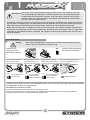
Driving
Driving an R/C car can be very diffi cult to master. We want you to have fun with your RC vehicle but please read the
cautions detailed below followed by some basic tips to help you understand how to use your RC vehicle for the fi rst
time.
• Drive the vehicle in a very large space, especially until you get the feel of driving the vehicle.
• Do not drive on public streets or highways. This could cause serious accidents, personal injuries and/or property
damage.
• Do not drive near members of the general public that could be placed at risk of injury.
• Do not drive in water or sand.
• 2.4Ghz radio frequency only functions in line of sight. If you drive behind a solid object or around a corner and
lose sight of the vehicle you may lose control of the car.
If you hold full throttle on the transmitter, the vehicle will keep accelerating and run very fast. It is diffi cult to steer the
vehicle running at high speeds. Drive the vehicle slowly by only pulling the throttle trigger a small amount to get used
to how fast the car can go.
When the car is running towards the driver, the directions of the steering wheel are reversed.
Once you become conformable driving the vehicle, practice driving on a track with cones.
Keep practising until you feel comfortable with the steering, throttle and brake at low speeds.
Once you are feeling comfortable try the above using reverse.
When you have mastered the basics you will be able to drive at higher speeds in a more controlled fashion.
Allow the car to cool down for 15 minutes between each run
DISCONNECT THE BATTERY PACK
AFTER USE!
Maintenance after driving
Proper maintenance is very important. Make sure to always perform appropriate maintenance after driving so that you
can enjoy driving without problems next time.
Completely remove all dirt and debris from the vehicle, especially in the suspension, drive shafts and steering parts.
Inspect each part and screws for loosening, missing parts or damages.
You should always make sure your wheels are tight and parts move freely after and before use.
Driving in wet conditions
This vehicle is designed to provide water protection for the on-board radio system components so it can be driven in
wet conditions. The vehicle is not designed to be completely submerged in water. Driving in wet conditions will require
additional maintenance.
Notes:
Never drive the vehicle in stormy conditions where lightning could be present. The transmitter is not waterproof,
always keep it protected from rain and water.
Remove all water/mud and dry the vehicle completely after driving. Check the vehicle for trapped water in the tyres,
transmission etc. Some metal parts like bearings and hinge pins will need lubrication after driving in wet or damp
conditions. The electric motor is not designed to be submerged in water. If water gets inside it can reduce the life of
the motor.
Most LiPo battery packs are not designed to operate in wet conditions. Consult the instruction manual or manufacturer
for limitations.
After running in water, dry off any water from the ESC and connectors.

14
Problem Cause Remedy
The vehicle does not move Transmitter or receiver is off Turn on both the transmitter and
receiver
Batteries are not placed correctly in
the transmitter
Place batteries in the transmitter
properly
The main battery is not charged
enough
Charge the main battery
The vehicle does not follow your
driving inputs
Transmitter or receiver is off Turn on both the transmitter and
receiver
Transmitter reverse switches are set
incorrectly
Check the reverse switch
settings
Transmitter End Point
Adjustments (EPA) are set
incorrectly
Check that your EPA Dials on
your transmitter.
Weak batteries in either the
transmitter or the car
Replace batteries in the
transmitter and recharge the
main battery.
The front and rear wheels rotate in
opposing directions
Incorrect user differential
placement
Insert the differential the
correct way
Trouble Shooting
Please read this section if you have any fault trying to operate the vehicle
If you encounter any other fault whilst operating the vehicle please contact your local hobby shop or alternatively
contact your local distributor.

15
VIEL SPASS! Aber lesen Sie bitte erst diese Anleitung !!
Wir wissen, dass Sie mit Ihrem Modell viel Spaß haben weden, aber BEVOR Sie das Modell in Betrieb nehmen,
lesen Sie bitte erst diese Informationen, damit Sie das Beste aus Ihrem Kauf machen können.
Inhaltsverzeichnis
Seite
Garantie 15
Sicherheitsmaßnahmen 16
Komponenten 16
Werkzeug 16
Für den Betrieb erforderlich 17
Batteriepack aufl aden 17
Batteriepack einsetzen 17
Sender 18
Lenkungstrimmung 18
Stromversorgung einschalten 19
Stromversorgung ausschalten 19
Elektronischer Geschwindigkeitsregler 20
Fahren 26
Wartung nach dem Fahren 26
Fehlersuche 27
Teileliste 54
Explosionszeichnung 65
90-Tage-Garantie auf Komponenten
Wir möchten, dass Sie an Ihrem Modell Spaß haben - aber lesen Sie bitte erst die nachstehenden
Ausführungen!
Für dieses Produkt gilt eine 90-Tage-Garantie auf Komponenten ab dem Kaufdatum. Wenn während dieser Zeit ein Teil des
Produkts infolge Fabrikationsmängeln ausfallen sollte, liegt es in unserem Ermessen, ob wir das Teil reparieren oder austauschen.
Wenn das Produkt einmal benutzt wurde, bieten wir keine Neu-für-Alt-Garantie.
Beachten Sie bitte, dass dieses Produkt kein Spielzeug ist und dass Kinder unter 14 Jahren von einem Erwachsenen beaufsichtigt
werden sollten. Es liegt in der Verantwortung der Eltern oder Aufsichtspersonen, sicherzustellen, dass Minderjährige
entsprechende Anleitung und Aufsicht erhalten.
Bei der Vermutung eines Problems mit dem Produkt, aus welchem Grunde auch immer, ist der Benutzer dafür verantwortlich, das
Problem zu untersuchen und für Abhilfe zu sorgen, bevor weitere Schäden entstehen.
Von der Garantie nicht gedeckt
Dies ist ein technisch ausgereiftes Hochleistungs-Modell, das mit Sorgfalt und Respekt behandelt werden sollte. Wir haben zwar
alles getan, um dieses Produkt so stabil und haltbar wie nur möglich zu machen, trotzdem können auf Grund der Natur dieses
Produkts Teile bei Zusammenstößen oder extremem Einsatz beschädigt werden oder brechen. Komponenten, die durch einen
Unfall, falsche Verwendung, mangelnde Wartung und Pfl ege oder Mißbrauch beschädigt wurden, fallen nicht unter die Garantie.
Garantieansprüche geltend machen
Mit Garantieansprüchen wenden Sie sich bitte zuerst an Ihren Händler. Ohne vorherige Genehmigung das Produkt nicht an den
Distributor einschicken. Sie brauchen das Produkt nicht als Ganzes einschicken, nur die beschädigte Komponente zusammen mit
einer Kopie des Kaufbelegs. In vielen Fällen ist es für Sie schneller und kostengünstiger, Ersatzteile in das Produkt einzubauen;
daher behalten wir uns das Recht vor, nur in solchen Fällen die Ersatzteile zu liefern.
Für jede eingeschickte Komponente, bei deren Überprüfung Ihr Distributor einen ungültigen Garantieanspruch festgestellt hat,
werden Ihnen vor der Rücksendung möglicherweise Prüfungs- und Bearbeitungskosten in Rechnung gestellt. Reparaturen, die als
Folge von Nachlässigkeit oder Mißbrauch erforderlich sind, werden in Rechnung gestellt, bevor Arbeiten am Produkt durchgeführt
werden. Wenn Sie sich entscheiden, dass keine Arbeiten ausgeführt werden sollen, hat der Distributor das Recht,
Bearbeitungs- und Versandkosten in Rechnung zu stellen.
Sie sollten Ihren Kaufbeleg an dieses Handbuch anheften, für den Fall, dass Sie ihn später noch einmal benötigen.

16
Sicherheitsmaßnahmen
Dieses Produkt ist ein authentisches funkgesteuertes Fahrzeug (RC-Fahrzeug) und kein Spielzeug. Bevor Sie das
Modell fahren lassen, sollten Sie diese Bedienungsanleitung sorgfältig durchgelesen und vollständig verstanden
haben. Wenn Sie mit RC-Fahrzeugen nicht vertraut sind, sollten Sie sich von jemandem beraten lassen, der sich bei
funkgesteuerten Fahrzeugen auskennt.
Nie die wiederaufl adbare Fahrbatterie mit falscher Polarität anschließen oder zerlegen. Wenn die Fahrbatterie falsch
angeschlossen wird, kann sehr gefährlicher starker Strom erzeugt werden.
Funkgesteuerte Modelle nie in der Nähe von Personen oder Tieren oder auf öffentlichen Straßen fahren lassen.
Dadurch können schwere Unfälle sowie Personen- und/oder Sachschäden entstehen.
Achten Sie darauf, dass der Hauptstecker des Ladegeräts immer gut zugänglich und niemals ohne Aufsicht
eingesteckt ist.
Wenn Sie aufl adbare AA Akkus für den Sender verwenden, achten Sie darauf, dass Sie ein geeignetes Ladegerät für
diesen Akkutyp erwerben.
ZIEHEN SIE DEN AKKUPACK
NACH DEM FAHREN AB!
5.5
mm
7
mm
1. 5
mm
2.0
mm
2.5
mm
Enthaltenes Werkzeug
Sender
Kleinteilebeutel
Komponenten
Diese Werkzeuge werden nicht mit dem Produkt mitgeliefert, sind aber für Arbeiten an und mit diesem Fahrzeug
empfohlen.
Schere, Seitenschneider, Spitzzange, Sechskant Schlüssel 1.5mm, 2.0mm, 2.5mm, Kreuzschraubenzieher
Empfohlenes Werkzeug
Kreuzschlüssel

17
4 * AA Batterien für
den Sender
Für den Betrieb erforderlich
Batteriepack aufl aden
Verwenden Sie für den enthaltenen Akkupack immer das enthaltene Ladegerät. Die Ladedauer für einen leeren
Akkupack beträgt ungefähr 6 Stunden. Laden Sie den Akku nicht länger als 6 Stunden um Überhitzung und
Beschädigung des Akkus zu vermeiden.
Einlegen der Senderbatterien
Batteriefach öffnen
um den leeren
Batterieschacht
freizulegen.
Die 4 AA Batterien in die
markierten Halterungen
einlegen. Dabei auf die
korrekte Richtung achten.
Falsch eingelegte Batterien
können zu Schäden führen.
Mit der 2.4GHz Technik wird
keine lange, ausziehbare
Antenne mehr benötigt. Die
Antenne Ihres Senders ist im
Inneren des Gehäuses
untergebracht.
Batteriepack einsetzen
Sie müssen den
Fahrakku in den offenen
Batterieschacht einsetzen.
Verwenden Sie bei Bedarf
die Aussparungen im
Chassis zur Verkabelung.
Verwenden Sie zur
Befestigung der Akkus
die dafür vorgesehenen
Haltebänder.
Wenn der Akku befestigt
und gesichert ist, verbinden
Sie den Stecker mit dem
Anschluss am
Geschwindigkeitsregler.
Achten Sie dabei auf die
richtige
Polarität: rot an rot, schwarz
an schwarz.
1
Warnhinweise
• Dieses Ladegerät kann nur für den enthaltenen Akkupack verwendet werden.
• Laden Sie den Akkupack nicht länger als 6 Stunden. Durch Überladung entsteht sehr viel Wärme und der Akkupack
wird beschädigt.
• Verwenden Sie das Ladegerät nur unter Aufsicht von Erwachsenen. Verwenden Sie es niemals in der Nähe von
Wasser oder wenn es feucht ist.
• Verwenden Sie das Ladegerät nicht wenn das Kabel ausgefranst oder beschädigt ist. Sonst kann ein Kurzschluss
zu einem Feuer führen.
• Wenn Sie vor dem Laden nicht genau wissen, wie voll der Akkupack noch ist, fahren Sie ihn solange, bis das
Fahrzeug langsam wird. Lassen Sie ihn abkühlen und laden Sie ihn dann.
1. Wählen Sie den passenden Stecker und stecken Sie das Kabel in das Ladegerät. Verwenden Sie immer den für
Ihr Land passenden Stecker.
2. Verbinden Sie das Ladegerät mit dem Stecker am enthaltenen Akku. Der Stecker ist verpolungssicher und hat
einen Clip um eine gute Verbindung sicher zu stellen. Stecken Sie den Stecker niemals mit Gewalt zusammen und
achten Sie immer auf die korrekte Polarität.
3. Das Ladegerät beginnt automatisch damit den Akkupack zu laden. Lassen Sie den Akkupack niemals länger als 6
Stunden mit dem Ladegerät verbunden und befolgen Sie die obenstehenden Warnhinweise.

18
Gashebel
1. Power LED
2. Lenkungs-Richtungsschalter
3. Gas-Richtungsschalter
4. Gas/Bremse-Endpunkt Einstellknöpfe
(Gas/Bremse)
5. Verbindungs-Knopf
6. Gas-Trimmung
7. Lenkungstrimmung
8. Dual Rate (D/R)-Schalter für Lenkung
9. Lenkrad
10. Gashebel
11. P.P.M.- Ausgang
12. An/Aus-Schalter
13. Ladeanschluss
• Drücken Sie den Gashebel nach
vorne um rückwärts zu fahren.
• Ziehen Sie den Gashebel nach
hinten um vorwärts zu fahren und
zu beschleunigen
• Für rückwärts erneut drücken.
Das Lenkrad nach links
oder rechts drehen, um
das Auto nach links bzw.
rechts zu lenken.
Die LenKungs- (ST) und Gas- (TH)
Richtungswechsel-Schalter stehen
standardmäßig auf “NOR” (Normal).
Um die Bewegungsrichtung der Lenkung
oder vom Gas umzukehren, stellen Sie
den Schalter auf “REV” (Reverse).
Die Dual-Rate Einstellung erlaubt es den
maximalen Weg des Servos oder des
Reglers für diesen Kanal
einzustellen. Bewegen Sie den D/R-
Hebel nach unten, um den maximalen
Lenkwinkel zu verkleinern, oder nach
oben, um ihn zu vergrößern.
Sender
Ihr Sender ist ein modernes Steuergerät, dass auch von einem Anfänger leicht zu bedienen und einzustellen ist.
Mit den unten aufgeführten Schritten stellen Sie sicher, dass der Sender für die Verwendung richtig vorbereitet ist
und dass Sie die vorhandenen Einstellmöglichkeiten vollständig verstehen.
Funktionsschalter am Sender
Lenkrad
Dual Rate (D/R)-Schalter für Lenkung Richtungswechsel-Schalter
Lenkungstrimmung
Wenn die Lenkung nicht gerade steht, wenn der Sender eingeschaltet ist, stellen Sie sicher, dass der Trimmungsregler sich in
Mittelstellung befi ndet, und stellen Sie das Servohorn des Autos bei Bedarf ein. Nehmen Sie dann Feineinstellungen mit der
Lenkungstrimmung vor, während das Fahrzeug fährt.
Gas-Trimmung
Leerlaufgaseinstellungen können durch Bewegen des
Gastrimmungshebels nach oben für mehr Gas und
nach unten für mehr Bremswirkung gemacht werden.
Lenkungstrimmung
Neutraleinstellungen der Lenkung können
durch Bewegen der Lenkungstrimmung
nach links oder rechts durchgeführt werden.
Wenn die Räder nach links
zeigen, drehen Sie den Regler im
Uhrzeigersinn.
Wenn die Räder nach rechts zeigen,
drehen Sie den Regler gegen den
Uhrzeigersinn.
Wenn Sie geradeaus zeigen, ist keine
Nachstellung notwendig.
Gasendpunkteinstellung (EPA)
Die Gas-EPA ermöglicht Ihnen die Einstellung des maximalen Wegs des Gaskanals.
„Hi“ stellt die EPA in Richtung Gasgeben ein, „Lo“ stellt die EPA in Richtung Bremsen ein. Drehen Sie den
Regler gegen den Uhrzeigersinn, um den maximalen Weg zu reduzieren oder im Uhrzeigersinn, um den
maximalen Weg zu erhöhen.
Wenn Sie diesen Sender mit einem elektrisch angetriebenen Fahrzeug verwenden, stellen Sie die
Endpunkte auf Maximalwerte ein.
12
1311

19
Stromversorgung einschalten
Zuerst den Sender, dann den Empfänger einschalten.
Bei eingeschaltetem Sender leuchtet die
LED-Batterieanzeige.
Den Empfänger einschalten. Die automatische Einstellung
des Geschwindigkeitsreglers ist nach kurzer Zeit
abgeschlossen. Bei Problemen mit dem automatischen
Setup schauen Sie bitte im Abschnitt zum
Geschwindigkeitsregler nach.
Die rote LED-Leuchte zeigt
an, ob die installierten AA-
Batterien ausreichend geladen
sind.
Die rote LED-Leuchte blinkt,
und es wird ein akustisches
Signal abgegeben, wenn die
Batterien ausgetauscht werden
müssen.
Power LED
Wenn Sie einen neuen Empfänger verwenden oder aus irgendeinem Grund das Signal verlieren, müssen Sie den
Sender und Empfänger neu verbinden.
• Bringen Sie Sender und Empfänger nah zusammen (innerhalb eines Meters).
• Schalten Sie den Sender an.
• Drücken und halten Sie den Einstell-Knopf am Empfänger. Schalten Sie nun den Empfänger an,
halten Sie dabei den Knopf gedrückt.
• Die Empfänger-LED wird schnell blinken. Lassen Sie dann nach einer Sekunde den Einstell-Knopf los.
• Drücken und halten Sie den Verbindungs-Knopf am Sender für eine Sekunde bis die LED des
Empfängers durchgängig leuchtet.
Verbinden des Senders mit dem Empfänger
1
Stromversorgung ausschalten
Zuerst den Empfänger, dann den Sender ausschalten.
Wenn Sie den Sender ausschalten, bevor das funkgesteuerte Auto ausgeschaltet ist,
verlieren Sie die Kontrolle über das funkgesteuerte Auto.
• Stellen Sie den Empfängerschalter auf Aus (Off).
• Schalten Sie den Sender aus.
• Ziehen Sie den Batteriestecker vom Stecker des Geschwindigkeitsreglers ab.
Fail-Safe Einsrellvorgang
Warnhinweise
Jeder neu durchgeführte Verbindungsvorgang löscht die Fail-Safe-Einstellungen.
1.
Schalten Sic den Sender ein Drücken Sie den Einstellknopf am Empfänger und lässcn Sie ihn wieder los. Die LED
wird blinken.
2.
Elektro Setup
Lassen Sie den Gashebel in der Neutralposition und drücken Sie den Einstellknopf. Die LED beginnt schnell zu
blinken. Lassen Sie die Bremse am Sender los sobald die LED durchgängig leuchtet. Lassen Sie danach den
Einstellknopf am Sender los.
Verbrenner Einsrellung
Halten Sie die Bremse am Sender voll gedrückt und drücken Sie den Einstellknopf. Die LED beginnt schnell zu
blinken. Lassen Sie die Bremse am Sender los sobald die LED durchgängig leuchtet. Lassen Sie danach den
Einstellknopf am Sender los.

20
Ziehen Sie nach dem Fahrern immer den Akku vom Regler ab.
Schließen Sie den Regler niemals verkehrt oder verpolt an. Bei falschem oder verpoltem Anschließen wird der
Regler beschädigt.
Bitte montieren Sie zusätzliche Entstörkondensatoren um einen guten Empfang zu haben.
Verwenden Sie keinen Motor mit weniger als 12 Turns wenn Sie einen 2S LiPo oder 6-Zellen NiMH Akku
verwenden (also keine Motoren mit 11T, 10T, 9T und weniger). Ein solcher Motor kann den Regler beschädigen.
(Auch wenn der Motor im sicheren Bereich liegt, kann es sein, dass der Regler aufgrund einer zu langen
Übersetzung oder den Streckenbedingungen (Off-Road, sehr viel Griff), zu warm wird und abschaltet).
Verwenden Sie keinen Motor mit weniger als 18 Turns wenn Sie einen 3S LiPo oder 9-Zellen NiMH Akku
verwenden (also keine Motoren mit 17T, 16T, 15T und weniger). Ein solcher Motor kann den Regler beschädigen.
(Auch wenn der Motor im sicheren Bereich liegt, kann es sein, dass der Regler aufgrund einer zu langen
Übersetzung oder
den Streckenbedingungen (Off-Road, sehr viel Griff), zu warm wird und abschaltet).
Wenn Sie durch Wasser gefahren sind, müssen Sie anschließen den Regler und die Stecker abtrocknen.
Während dem Fahren wird der Regler heiß. Berühren Sie den Kühlkörper nicht, da Sie sich sonst verbrennen
können.
Der Regler besitzt 2 Akkumodi, die ausgewählt werden können (NiMH und LiPo). Der Akkutyp muss passend
zum verwendeten Akku eingestellt werden. Wenn Sie das nicht tun, kann der Akku explodieren, sich aufblähen,
qualmen oder unbrauchbar werden.
Warnhinweise
Wenn Sie diesen Anweisungen nicht folgen, können Sie oder an dere verletzt werden.
Es kann auch sein, dass dabei sachschaden an anderen Dingen oder ihrem Autro entsteht
Elektronischer Geschwindigkeitsregler
MSC-30BR-WP-Eigenschaften:
Modell MSC-30BR-WP
Vorwärts Dauer- /
Spitzenstrom
40A / 180A
Rückwärts Dauer- /
Spitzenstrom
20A / 90A
Widerstand Vorwärts : 0.002 Ohm,
Rückwärts : 0.004 Ohm
Anwendungen 1/10 scale On-Road und Off-Road
Motorlimit 2S LiPo / 6
Zellen NiMh
540er oder 550er Motor ≥ 12T
U/min < 30000 @ 7.2V
3S LiPo / 9
Zellen NiMh
540er oder 550er Motor ≥ 18T
U/min < 20000 @ 7.2V
Eingang 5-9 Zellen NiMh oder 2-3S LiPo
Integriertes BEC 6V/2A
PWM-Frequenz 1KHz
Abmessungen 46,5 x 34 x 28,5mm
Gewicht 65g
Seite wird geladen ...
Seite wird geladen ...
Seite wird geladen ...
Seite wird geladen ...
Seite wird geladen ...
Seite wird geladen ...
Seite wird geladen ...
Seite wird geladen ...
Seite wird geladen ...
Seite wird geladen ...
Seite wird geladen ...
Seite wird geladen ...
Seite wird geladen ...
Seite wird geladen ...
Seite wird geladen ...
Seite wird geladen ...
Seite wird geladen ...
Seite wird geladen ...
Seite wird geladen ...
Seite wird geladen ...
Seite wird geladen ...
Seite wird geladen ...
Seite wird geladen ...
Seite wird geladen ...
Seite wird geladen ...
Seite wird geladen ...
Seite wird geladen ...
Seite wird geladen ...
Seite wird geladen ...
Seite wird geladen ...
Seite wird geladen ...
Seite wird geladen ...
Seite wird geladen ...
Seite wird geladen ...
Seite wird geladen ...
Seite wird geladen ...
Seite wird geladen ...
Seite wird geladen ...
Seite wird geladen ...
Seite wird geladen ...
Seite wird geladen ...
Seite wird geladen ...
Seite wird geladen ...
Seite wird geladen ...
Seite wird geladen ...
Seite wird geladen ...
Seite wird geladen ...
Seite wird geladen ...
Seite wird geladen ...
Seite wird geladen ...
Seite wird geladen ...
Seite wird geladen ...
Seite wird geladen ...
Seite wird geladen ...
Seite wird geladen ...
Seite wird geladen ...
Seite wird geladen ...
Seite wird geladen ...
Seite wird geladen ...
Seite wird geladen ...
-
 1
1
-
 2
2
-
 3
3
-
 4
4
-
 5
5
-
 6
6
-
 7
7
-
 8
8
-
 9
9
-
 10
10
-
 11
11
-
 12
12
-
 13
13
-
 14
14
-
 15
15
-
 16
16
-
 17
17
-
 18
18
-
 19
19
-
 20
20
-
 21
21
-
 22
22
-
 23
23
-
 24
24
-
 25
25
-
 26
26
-
 27
27
-
 28
28
-
 29
29
-
 30
30
-
 31
31
-
 32
32
-
 33
33
-
 34
34
-
 35
35
-
 36
36
-
 37
37
-
 38
38
-
 39
39
-
 40
40
-
 41
41
-
 42
42
-
 43
43
-
 44
44
-
 45
45
-
 46
46
-
 47
47
-
 48
48
-
 49
49
-
 50
50
-
 51
51
-
 52
52
-
 53
53
-
 54
54
-
 55
55
-
 56
56
-
 57
57
-
 58
58
-
 59
59
-
 60
60
-
 61
61
-
 62
62
-
 63
63
-
 64
64
-
 65
65
-
 66
66
-
 67
67
-
 68
68
-
 69
69
-
 70
70
-
 71
71
-
 72
72
-
 73
73
-
 74
74
-
 75
75
-
 76
76
-
 77
77
-
 78
78
-
 79
79
-
 80
80


HPI Racing Maverick Strada Benutzerhandbuch
- Kategorie
- Ferngesteuertes Spielzeug
- Typ
- Benutzerhandbuch
in anderen Sprachen
Verwandte Artikel
-
HPI Racing Maverick Phantom Benutzerhandbuch
-
HPI Racing MSC-30BR-WP Benutzerhandbuch
-
-
-
HPI Racing MSC-30BL-WP Benutzerhandbuch
-
-
-
-
-
Andere Dokumente
-
Maverick TimberWolf 1/10th RTR Brushless SCT Benutzerhandbuch
-
Axial AXI03000T1 Bedienungsanleitung
-
 Hobbytech NXT SPIRIT Benutzerhandbuch
-
Maverick Strada MT Installationsanleitung
-
-
ECX Revenge E Benutzerhandbuch
-
-
REDCAT GEN8 SCOUT II - V2 Bedienungsanleitung
-
-
