
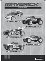
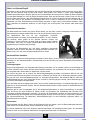
INSTRUCTION MANUAL
MV22249
English - 2-12
Français - 13-23
Deutsch - 24-34
Español - 35-45
5
050864 005593

Table of contents
Page
Warranty 3
90 Day Component Warranty 3
Not covered by warranty 3
How to claim against your warranty 3
Specifications 4
Items required for operation 4
Electronic Speed Controller 4
Features 4
Technical Information 4
Set-Up Instructions 4
Transmitter 5
Preparing the transmitter 5
Function switches 5
Throttle Trigger 5
Steering Wheel 5
Throttle/Steering Trim 5
End Point Adjustment Dials 5
Safety Precautions 6
Recommended Tools 6
Charging the battery pack 6
Cautions 6
Driving 7
Installing the battery pack 8
Turning on the power 8
Turning off the power 9
Maintenance after driving 9
Troubleshooting 9
Tuning 10
Front steering toe angle 10
Camber 10
Gearing 10
Pinion and Spur Gear Meshing 11
Adjusting the ride height 11
Adjusting the body height 11
Upgrading your performance 11
Getting into racing 11
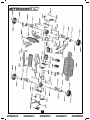
Parts Listing 12
Strada TC Exploded Diagram 46
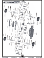
Strada MT Exploded Diagram 47
Strada XB Exploded Diagram 48
Strada XT Exploded Diagram 49
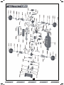
Sub Assemblies Exploded Diagram 50
Strada SC Exploded Diagram 51
We know you will have great fun with your model, but to get the best from your purchase please read this information
BEFORE you operate the model.
HAVE FUN! But please read this first !!
2

90 Day Component Warranty
We want you to enjoy your purchase, but please read this first!
This product is covered by a 90 day component warranty from date of purchase. If any part of the product fails as a
result of faulty manufacture during this period then we will repair or replace that part at our discretion.
We do not operate a new for old warranty once the product has been used.
Please note this product is not a toy and it is recommended that children 14 and under are supervised by an adult. It
is the responsibility of the parent or guardian to ensure minors are given appropriate guidance and supervision.
If you suspect there is a problem with the product, for whatever reason, it is the user’s responsibility to investigate
and take steps to rectify the problem before further damage occurs.
Not Covered By Warranty
This is a sophisticated, high performance model and should be treated with care and respect. Every effort has been
made to make this product as strong and durable as possible, however due to the nature of this product, it is still
possible to break or damage parts through crashing or extreme use. Components damaged as a result of crash
damage, improper use, lack of maintenance or abuse is not covered by the warranty.
How to Claim Against your Warranty
For warranty claims please first contact your supplying retailer. Do not return the product to your distributor without
their prior approval. You may not need to return the product in full, only the damaged component along with a copy
of your purchase receipt. In many cases it is faster and more cost effective for the user to fit the replacement part(s)
to the product & therefore we reserve the right to supply parts only in these instances.
Any returned component that is inspected by your distributor and found to have an invalid warranty claim may be
subject to an inspection and handling fee before it can be returned. Any repairs required as a result of neglect or
misuse will be charged before any work is carried out on the product. If you decide not to have any work carried out
the distributor reserves the right to charge a handling and a shipping fee.
Please attach your proof of purchase in the manual as you may need it again in the future.
3
Warranty

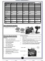
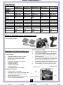
Items required for operation
8 * AA Batteries for the Transmitter
Electronic Speed Controller
Features
• 6.0Volt — 8.4Volt Power Input
• High Frequency Drive System
• Forward, Reverse & Brake Linear Operation
• Automatic Setup System
• Over Current Protection
• Thermal Protection
• Low Voltage Protection
• LED with audible beep
• 13 Turn Brushed Motor Limit
Technical Information
• PWM frequency 1.5khz (fixed)
• 200 A drive FET’s & 100A Reverse FET’s
• Case dimensions: 33mm*27mm*25mm
• Silicone Wire 14 Gauge
• Weight 4.5g with connectors and switch
• BEC Voltage 6.0V
Motor Cables
Battery
Cables
LED
Receiver Cables
FET’s
Set-Up Instructions
1. With the speed control switch set to off, plug in a suitable
battery pack.
2. With the transmitter switched on and throttle trim set to
the centre, turn on the speed control.
3. To Indicate the speed control is working correctly its LED
will flash followed by 3 beeps and a further flash.
4. If necessary adjust the throttle trim of the transmitter so
your car is stationary with no throttle or brake applied.
5. Your speed control is fully installed and ready to use.
4
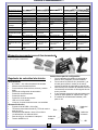
Specifications
Length
380mm 400mm 400mm 400mm 460mm
Width
200mm 250mm 300mm 310mm 250mm
Height
112mm 160mm 160mm 185mm 160mm
Wheel base
260mm 275mm 275mm 275mm 275mm
Drive System
4wd Shaft Drive 4wd Shaft Drive 4wd Shaft Drive 4wd Shaft Drive 4wd Shaft Drive
Gear Ratio
7.37:1 11.00:1 13.36:1 13.36:1 8.04:1
Ground
Clearance
4.5mm 26mm 30mm 35mm 26mm
Diameter of
wheel
65mm 86mm 105mm 118mm 86mm
Width of wheel
26mm 32mm F 40mm R 60mm 52mm 42mm
Motor
MM-22 540 size MM-22 540 size MM-22 540 size MM-22 540 size MM-22 540 size
Servo
Maverick MS-22 Maverick MS-22 Maverick MS-22 Maverick MS-22 Maverick MS-22
Receiver
MRX-22 27mhz AM MRX-22 27mhz AM MRX-22 27mhz AM MRX-22 27mhz AM MRX-22 27mhz AM
Speed Control
MSC-22 13 turn limit
Fwd/ Rev
MSC-22 13 turn
limit Fwd/Rev
MSC-22 13 turn
limit Fwd/Rev
MSC-22 13 turn limit
Fwd/Rev
MSC-22 13 turn
limit Fwd/Rev
Battery
MBP-22 1800 mAh
Ni-MH
MBP-22 1800 mAh
Ni-MH
MBP-22 1800 mAh
Ni-MH
MBP-22 1800 mAh
Ni-MH
MBP-22 1800 mAh
Ni-MH

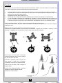
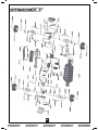
Transmitter
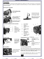
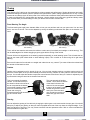
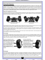
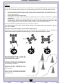
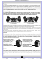
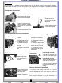
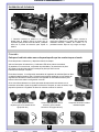
Preparing the transmitter
The function switches on the transmitter
1. Aerial
2. Throttle Trim
3. Steering Trim
4. Frequency Crystal
5. Throttle Trigger
6. Power Switch
7. Battery level indicator
8. Steering reverse switch
9. Throttle reverse switch
10. Steering Control (wheel)
1
8
9
7
6
10
2
3
4
5
Throttle/Steering Trim
Throttle Trim
1. Turn anti clockwise for more
brake
2. Turn clockwise for more
throttle
Steering Trim
1. Turn anti clockwise to trim to
the left
2. Turn clockwise to trim to the
right
1 2
1 2
Throttle Trigger
1. Push the trigger forward to
brake
2. Pull the trigger backwards to
go forwards and speed up
2
1
Neutral
Steering Wheel
Turn the steering wheel to the left
or right to make the go vehicle left
or right
L
R
Insert the aerial into
the hole and turn
clockwise until it is
tightly secured.
Open the battery holding
tray to expose the empty
battery slots.
Insert 8 AA batteries into
the marked spaces.
Please note the correct
direction of the batteries
Incorrect battery insertion
could lead to damage
Close the battery holding
tray to safely conceal and
secure the batteries.
Transmitter
Your Transmitter is an advanced controller designed for the beginner to be easy to use and tune. You will need to
follow the steps below to ensure you prepare the controller correctly for use and understand the adjustment
possibilities available.
Throttle/Steering Trim
1 2
1 2
5
Insert 8 AA batteries into
the marked spaces.
Please note the correct
direction of the batteries
Incorrect battery insertion
could lead to damage
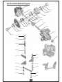
Preparing the transmitter
Insert the aerial into the
hole and turn clockwise
until it is tightly secured.
Make sure you never over
extend the aerial as this
will cause it to break.
Open the battery holding
tray to expose the empty
battery slots.
1. Aerial
2. Throttle Trim
3. Steering Trim
4. Frequency Crystal
5. Throttle Trigger
6. Steering Control
(wheel)
7. Power Switch
8. Battery level
indicator
9. Steering reverse
switch
10. Throttle reverse
switch
11. Steering Throw
dial
12. Steering End
Point dials (left/
right lock)
13. Throttle End Point
dials (low/high
points)
The function switches on the transmitter
6
2
3
1
4
5
8
9
7
10
11 12
13
Throttle Trigger
Steering Wheel
2
1
Neutral
1. Push the trigger
forward to brake
2. Pull the trigger
backwards to go
forwards and
speed up
L
R
Turn the steering wheel
to the left or right to
make the go vehicle
left or right
Throttle Trim
1. Turn anti clockwise for
more brake
2. Turn clockwise for more
throttle
Steering Trim
1. Turn anti clockwise to trim
to the left
2. Turn clockwise to trim to
the right
End Point Adjustment Dials
Both steering and throttle have high point adjustments which
allows you to adjust left and right steering lock & high and low
throttle points. You can also adjust the overall lock your
vehicle has after adjusting your individual side locks.
All of these adjustment dials require an anti clockwise
movement for more and clockwise movement for less.

Safety precautions
This product is an authentic radio controlled vehicle (RC vehicle) and it is not a toy. Read and understand this
instruction manual thoroughly before running the model. If you are not familiar with RC vehicles, we recommend that
you ask someone familiar with RC vehicles for advice.
Never connect the rechargeable drive battery in the reverse polarity or disassemble the battery. If the drive battery is
used in the wrong way, high current can be generated and it is very dangerous.
Never run RC models near people or animals, or on public streets or highways. This could cause serious accidents,
personal injuries, and/or property damage.
Recommended Tools
These tools are not included with the product but are recommended for use whilst working with this vehicle
Scissors, Mini Screwdrivers, Hexagonal Screwdrivers 1.5mm, 2.0mm, 2.5mm, 3.0mm, 4-Way Cross Wrench (Small),
4-Way Cross Wrench (Large), Side Cutters, Needle Nose Pliers
Charging the battery pack
Always use the included charger for the included battery pack. Do not use any other battery packs. Charging time for
an empty battery pack is about 6 hours. Do not charge the battery pack longer than 6 hours to avoid overheating and
battery damage.
Cautions
• This charger can be used only for the battery pack included in this kit.
• Do not charge the battery pack for longer than 6 hours. Overcharging generates excessive heat and will
damage the battery pack.
• Use the charger with adult supervision. Do not use the charger near water or when wet.
• Do not use the charger if the wire is frayed or worn. If the wire is frayed or worn a short circuit can cause a fire
or burns.
• If you are not sure about the level of the battery pack before charging use it in the vehicle until the vehicle
slows, leave to cool and then recharge.
Whilst your battery pack is charging please read the next section on driving.
6

Driving
Driving an R/C car can be very difficult to master but here are some basic tips to help you to understand how to use it
before you have your first attempt
• Drive the vehicle in a very large space, especially until you get the feel of driving the product.
• Do not run on public streets or highways. This could cause serious accidents, personal injuries and/or property
damage.
• Do not run in water or sand.
• Make sure everyone is using different frequencies when driving together in the same area.
• If you keep pulling the throttle trigger on the transmitter, the vehicle will keep accelerating and run very fast. It
is difficult to steer the vehicle running at high speed until you become used to driving. Drive the vehicle slowly
by pulling the throttle trigger to the fullest and quickly releasing it.
You can turn the vehicle right or left while it is running.
When the vehicle is running toward you, you need to operate the steering wheel in the opposite direction to the
operation when the vehicle is running away from you.
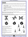
Practice turning the vehicle, referring to the following:
Rather than just paying attention to the direction of the steering wheel, imagine that you are at the centre of the
steering wheel, looking ahead of the vehicle, to turn in the direction you like.
Once you become conformable driving the
vehicle, practice driving on a track with cones.
Keep practising until you feel comfortable with
the steering, throttle and brake at low speeds.
Once you are feeling comfortable try using
reverse.
When you have mastered the basics you will
be able to drive at higher speeds in a more
controlled fashion.
7

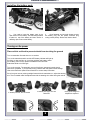
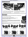
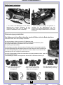
Installing the battery pack
1. You need to insert the battery pack in the
open section for the battery. Use the strap provided
to place on top of the battery and then use the 2
retaining clips to secure the battery.
2. Once fastened and secured please connect
the battery plug into the speed controller plug
noting correct polarity. Red to red, black to black.
Turning on the power
Place vehicle on block to prevent wheels from touching the ground
Turn on transmitter first and then turn on receiver.
Turn on the transmitter switch and the LED battery indicator will light up.
If it blinks or does not light up, check the polarities and battery power.
If the battery power is low, replace the batteries with new ones.
Extend the aerial to its full length.
Turn on the receiver. The automatic set-up of the factory set speed control should
have been completed. If you experience any problems with the speed control settings
refer to the Electronic Speed Control Section for correct setup information.
If the front tyres are not pointing straight forward with the transmitter on, adjust the steering
trim. Then if needed make fine adjustments with the steering trim whilst driving the vehicle.
If wheels point left, turn clockwise
If wheels point right, turn anti
clockwise.
If they point straight no
adjustment required.
8

Turning off the power
Turn off receiver first and then turn off transmitter.
If you switch off the transmitter first before the R/C car, you may lose control of the R/C car.
• Turn off the receiver switch.
• Turn off the transmitter switch and lower the aerial.
• Disconnect the battery connector from the speed control connector.
Make sure to always turn off the power in this order (opposite order of turning on the power). If you turn off the power
in the wrong order, the vehicle may run out of control and this can be very dangerous.
Always disconnect the battery connector from the speed control connector after driving.
Maintenance after driving
Proper maintenance is very important. Make sure to always perform appropriate maintenance after driving so that
you can enjoy driving without problems next time.
Completely remove all dirt and debris from the vehicle, especially in the suspension, drive shafts and steering parts.
Inspect each part and screw for loosening, missing or damages.
You should always make sure your wheels are tight and parts move freely after and before use.
Trouble Shooting
Please read this section if you have any fault trying to operate the vehicle
If you encounter any other fault whilst operating the vehicle please contact your local hobby shop or alternatively
contact your local distributor.
9
Problem Cause Remedy
The vehicle does not move
The vehicle does not follow your
driving inputs
Transmitter or receiver is off
Batteries are not placed correctly
in the transmitter
The main battery is not charged
Transmitter or receiver is off
Transmitter or receiver aerial is
not fully extended
Some one else is using the same
frequency as you
Turn on both the transmitter and
receiver
Place batteries in the transmitter
properly
Charge the main battery
Turn on both the transmitter and
receiver
Fully extend both aerials
Change your frequency crystals to
one which no one else around you is
using or wait until the driver of the
same frequency has finished driving
or go to a different place to drive
your vehicle
The front and rear wheels rotate
in opposing directions
Incorrect user differential
placement
Insert the differential the correct way

Tuning
Your Maverick R/C vehicle can be customised to enhance speed and performance. Simple adjustments and easily
maintained settings will assure optimum operation and performance. When making adjustments, do so only in small
increments and always check for other parts of the vehicle that are affected. Many aftermarket options are available
to make your Maverick R/C vehicle faster and stronger. Use this section as a basic tuning guide and always make
sure you write down your base settings in case you need to refer to them at a later date.
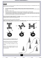
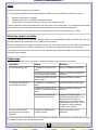
Front Steering Toe Angle
The front steering toe angle has a dramatic affect on how your car performs and how your tyres wear. You can have
toe-in, zero toe or toe-out. This can be adjusted by turning the steering turnbuckles with pliers in the direction you
need.
Toe-in will be less reactive and cause the vehicle to under steer (front wheel push straight on whilst turning). This
can be advantageous for drivers struggling to get to grips with the driving of the vehicle.
Toe-out will be more aggressive on the steering response especially on small steering inputs. This will make the car
want to over steer (rear wheels slide on small steering inputs). This is useful as a race tuning aid to gain extra
steering.
Zero toe will make the front wheels run straight and make the car very neutral. Tyre wear will also be reduced and
the vehicle will feel easier to drive.
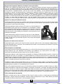
Camber
Camber can be adjusted on all 4 wheels of the car. You can have negative camber or positive camber which will
affect the contact patch of the tyre both statically and whilst cornering. Camber is mainly used to control the wear of
the tyre. You should adjust the camber to equal the wear all across the surface of the tyre. Camber is adjusted by the
top turnbuckle linking the wheel to the chassis front and rear.
Gearing
You can adjust the gearing of the vehicle by changing the pinion gear on the motor and/or the spur gear. You should
always try to adjust your gearing so that you reach top speed two thirds of the way down the longest straight. If you
gear the vehicle too high then you may cause excessive heat and premature wear. Stick to motor manufacturers
recommendations on gear ratio.
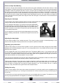
Exaggerated Toe-In Setting (never run
this much!)
Exaggerated Toe-Out Setting (never run
this much!)
This is an example of negative
camber. This is when the top of
the wheel is closer to the centre of
the car compared to the bottom
of the wheel. Negative camber will
give more contact area in the
corner and more grip.
Excessive amounts will cause less
grip and uneven wear.
This is an example of positive
camber. This is when the bottom
of the wheel is closer to the
centre of the car compared
to the top of the wheel. Positive
camber will give less contact
area in the corner and less
grip. Excessive amounts will
cause less grip and uneven
wear.
10

Pinion and Spur Gear Meshing
The pinion is the gear that is attached to the motor and the spur gear is attached to the drive train of the car. These
work together to make the transmission turn and drive the car. These parts will need to be correctly spaced together
(meshed) to make sure excessive wear does not occur. Once the motor is installed and the pinion gear is tight check
the mesh by trying to gently rock the spur gear with your finger (make sure no battery is connected). If you can rock
the spur gear a lot then it is too loose, alternatively if the spur gear does not rock then it is too tight. The easiest way
is to insert a thin piece of plastic (like a shopping carrier bag) between the pinion and motor before you tighten the
motor. Once tight remove the plastic carrier bag and check the mesh again. A small amount of rock should be there
on the spur gear.
Adjusting the ride height
The ride height of the chassis will greatly influence how the vehicle handles the surface it is being used on. A circuit
racing car will have less ride height (6mm) than an off road car (20mm).
Adjusting the body height
You can alter the height of your vehicles body shell. This is done by either pins/clips or screws depending on your
vehicle on the body posts. The body shells come in the optimum position as standard.
Upgrading your performance
There are many things you could choose to upgrade on an R/C vehicle to make it faster, stronger and more reliable.
Maverick cars have been designed to give you a very strong platform that is very reliable and fast enough to learn
about R/C cars in general.
You can upgrade the motor up to the speed controls limit. The Maverick MSC-22 has a 13 turn brushed motor limit
and should not be used with anything lower than a 13 turn. Optional speed control are available which have lower
motor limits. The Maverick MBP-22 1800 mAh Ni-MH battery pack can be upgraded which will give you more run
time, faster acceleration and more top speed from your vehicle.
Tyres can also be changed like real road cars. Many aftermarket options are available for different conditions but the
standard Maverick tyres have been specially chosen to meet the users needs.
There are many aspects of tuning that are too complex to describe in detail in this basic guide. You can adjust your
shock absorber oil, pistons, springs and shock position to alter how your vehicle takes the bumps. You can adjust
your roll centres to change how much grip the chassis generates in roll. You can adjust rear toe in, steering
ackerman, droop, diff tensions and types of diff to find extra performance.
Getting into racing
There is a wide network of R/C racing clubs around the world and if you feel the need for some competitive racing
then they may be the thing for you. Try doing an internet search for ‘remote controlled car racing’ and this will get you
on your way.
You should find your local model shop will be able to give you invaluable advice and support. The easiest way to find
one is by buying a specialist R/C car magazine or via looking in the telephone directory.
You can adjust the ride height on your vehicle by using the supplied black
composite spacers on the shock absorber body. The more spacers you add
the higher the chassis will sit of the ground. Make sure you add the same
amount of spacers on each side as unequal left to right ride height will result
in inconsistent performance.
You can adjust the front and rear ride height independently which will also
alter the handling characteristics. It is best to have equal front and rear ride
height.
11

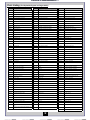
Parts Listing (For Exploded diagram see Pages 46-51)
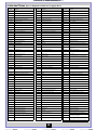
12
Part No Description
Part No Description
Part No Description
MV22001 Shock Absorber Assembly (2Pcs)
MV22054
Countersunk Cross Head Self-Tapping Screw M3x15mm
(9Pcs)
MV22116 Shock Absorber (2Pcs)
MV22002 Dogbone 55mm (2Pcs)
MV22055 Countersunk Screw M3x10mm (8Pcs)
MV22117 Front Bumper
MV22003 Rear Bumper MV22056 Cap Head Screw M3x10mm (10pcs) MV22118 Rear Bumper
MV22004 Rear Lower Suspension Arm (2Pcs) MV22057 Round Head Screw M3x10mm (6Pcs) MV22119 Front Lower Suspension Arm (2pcs)
MV22005 Front Lower Suspension Arm (2Pcs) MV22058 Grub Screw M3x4mm (8Pcs) MV22120 Rear Lower Suspension Arm (2pcs)
MV22006 Front Top Plate MV22059 Grub Screw M4x4 (8Pcs) MV22121 Body Mount Post
MV22007 Body Post (4Pcs) MV22060 Wheel Hex. (8Pcs) MV22122 Shock Tower
MV22008 Suspension Upper Arm Linkages (2Pcs) MV22061 Steering Bushing (12Pcs) MV22123 Rear Lower Arm Outer Pin (2pcs)
MV22009 Rear Upright & Set Screws (2Pcs) MV22062 M3 Nylon Locknut (6Pcs) MV22124 Front Lower Arm Outer Pin (2pcs)
MV22010 Steering Hubs (2Pcs) MV22063 Body Strada TC Painted & Trimmed Red MV22125 Shock Ball Head Holder (4Pcs)
MV22011 Steering Holder (2Pcs) MV22064 Body Strada XB Painted & Trimmed Red MV22126 Domed Head Disc Screw M3x10 (8Pcs)
MV22012 Universal Joint Cup (2Pcs)
MV22065 Body Strada XT Painted & Trimmed Red
MV22127 Pin 2x10 (10Pcs)
MV22013 Suspension Reinforcement Brace (2Pcs) MV22066 Body Strada MT Painted & Trimmed Red MV22128 Bumper Post (4Pcs)
MV22014 Rear Suspension Arm Holder MV22067 Rolling Bearing 15x10x4 (6pcs) MV22129 Dogbone 89.5mm (2Pcs)
MV22015 Front Suspension Arm Holder MV22068 Rolling Bearing 10x5x4mm (8pcs) MV22130 Bumper Spring (4Pcs)
MV22017 Differential Main Gear MV22069 Chassis MV22131 Steering Linkage (2Pcs)
MV22018 Differential Drive Pinion MV22070 Radio Tray MV22132 Motor Pinion Gear 19T (0.6 Module)
MV22019 Differential Universal Cup Joint (2Pcs) MV22071 Centre Dogbone MV22133 Spur Gear 64T (0.6Module)
MV22020 Front Axle (2Pcs) MV22072 Spur Gear 58T (0.6 Module) MV22136
1/10 Truggy Wheel & Tyre Assembly 12mm Hex Mount
105mm Dia.x 55mm Wide
MV22021 Front Shock Tower MV22073 Motor Gear 26T (0.6 Module) MV22137 Truggy Shock Absorber (2Pcs)
MV22022 Front Suspension Lower Arm Pin Inner (2Pcs) MV22074 Chassis Top Deck MV22138 Steering Assembly
MV22023 E-clip Set (12Pcs) MV22075 Motor Mount MV22139 Front Axle (2Pcs)
MV22024 Ball Head Screw (6Pcs) MV22076 Switch Cover MV22142
MT Chrome Wheel & Tyre Assembly 115mm Dia. X
55mm Wide
MV22025 Differential Case, Seals & Washers (2Pcs) MV22077 Battery Cover Post (2pcs) MV22143 MTX-22 27MHz AM Pistol Grip 2CH Transmitter
MV22026 Rear Shock Tower MV22078 Battery Cover MV22234 Motor Gear 21T (0.6 Module)
MV22027 Gear Box Case
MV22079 Motor
MV22235 Motor Gear 25T (0.6 Module)
MV22028 Front Foam Bumper MV22080 Radio Tray Holder MV22236 Motor Gear 27T (0.6 Module)
MV22029 Body Clips (8Pcs) MV22081 Motor Gear 23T (0.6 Module) MV22237 Motor Gear 29T (0.6 Module)
MV22030 M4 Nylon Nut (8Pcs) MV22082 Gearbox Drive Shaft & E-Clip MV22238 Spur Gear Adaptor to 48/64DP Standard Spur Gears
MV22031 Antenna Pipe (4Pcs) MV22085 Motor Heatsink MV22239 Body Strada TC Painted & Trimmed Blue
MV22032 Rear Lower Arm Outer Pin (2Pcs)
MV22086 Chassis
MV22240 Body Strada XB Painted & Trimmed Blue
MV22033 Front Lower Arm Inner Pin (2Pcs) MV22087 Radio Tray MV22241 Body Strada XT Painted & Trimmed Blue
MV22034 Rear Lower Arm Inner Pin ( 2Pcs) MV22088 Centre Dogbone MV22242 Body Strada MT Painted & Trimmed Blue
MV22035 Rear Body Post Mounting Plate MV22089 Battery Corner Holder MV22243 Radio On / Off Switch
MV22036 Differential Pinions & Pin MV22091 Front Bumper MV22244 1/10 Touring Car Wheel & Tyre Assembly
MV22037 MRX-22 Receiver 27Mhz AM MV22092 Front Body Mount MV22245 MBP-22 1800 mah Ni-MH Battery Stick Pack
MV22038 Servo Arm (2Pcs) MV22093 Tail Wing post MV22246 Motor Gear 17T (0.6 Module)
MV22039 MS-22 Steering Servo MV22096 Shock Ball Head MV22247 Motor Gear 14T (0.6 Module)
MV22040 Steering Link MV22100 1/10 Buggy Chrome Front Wheel & Tyre Assembly MV22248 Shock Absorber Assembly (2Pcs)
MV22041 Steering Post Assembly MV22101 Front Lower Suspension Arm MV22249
Maverick Strada MT/TC/XB/XT Instructions & Spares
Manual
MV22042 Front Bumper Plate MV22102 Rear Lower Suspension Arm MV222050 MTX22 Transmitter Aerial
MV22043 O-Ring Seals (12Pcs) MV22103 Front Shock Plate MV22251 MSC22 Electronic Speed Controller V2
MV22044 7.2V Stick Pack Battery Charger UK 3-Pin
MV22104 Rear Shock Plate
MV22415 Front Bumper Set SC
MV22045 7.2V Stick Pack Battery Charger EU 2-Pin MV22105 Steering Linkage (2pcs) MV22416 Rear Bumper Set SC
MV22046 Round Head Screw M3x8mm (6Pcs) MV22106 Tail Wing Brace MV22417 Body Posts (4Pcs) SC
MV22047 Round Head Self-Tapping Screw M3x10mm (10Pcs) MV22107 Front Lower Arm Outer Pin (2pcs) MV22418 Body Post Mount (Fr 2pcs) SC
MV22048 Round Head Screw M3x12mm (6Pcs) MV22108 Rear Lower Arm Outer Pin (2pcs) MV22419 Body Post Mount (Rr 2pcs) SC
MV22049 Round Head Screw M3x18 (4Pcs) MV22109 Wing Support (2Pcs) MV22420 Dogbone 89.5mm (2pcs)
MV22050 Round Head Screw M2x8mm (8Pcs) MV22110 Rear Wing MV22421 Wheel Axle (2pcs) SC
MV22051 Round Head Screw M2x10 (10Pcs) MV22111 Dogbone Fr & Rr 80mm (2Pcs) MV22422 Wheel Hex Adaptor (4Pcs) SC
MV22052
Countersunk Cross Head Self-Tapping Screw M3x10mm
(15Pcs)
MV22112 Shock Ball End (4Pcs)
MV22423 Rear Anti-Squat Plate SC
MV22053
Countersunk Cross Head Self-Tapping Screw M3x14mm
(13Pcs)
MV22115 1/10 Buggy Chrome Rear Wheel & Tyre Assembly
MV22426 Wheel and Tyre Set (2Pcs)SC
MV22427 Ball Head Self-Tapping Screw 2.6x12mm (4Pcs)

Sommaire
Page
Garantie 14
Garantie du composant de 90 jours 14
Non couvert par la garantie 14
Comment revendiquer votre garantie 14
Spécifications 15
Éléments obligatoires pour le fonctionnement 15
Régulateur de vitesse électronique 15
Caractéristiques 15
Information technique 15
Instructions de montage 15
Émetteur 16
Préparation de l’émetteur 16
Commandes des fonctions 16
Commande d’accélérateur 16
Roue directrice 16
Régulateur Accélération / Direction 16
Sélecteur de réglage de point limite 16
Mesures de sécurité 17
Outils recommandés 17
Charge du bloc -piles 17
Attention 17
Conduite 18
Installation du bloc -piles 19
Mise en marche 19
Arrêt 20
Entretien après la conduite 20
Dépannage 20
Accord de fréquence 21
Angle de braquage avant renforcé 21
Carrossage 21
Embrayage 21
Engrenage à roue droite et du pignon 21
Réglage du niveau du véhicule 22
Réglage de hauteur de caisse 22
Amélioration de vos résultats 22
Entrée en course 22
Liste des Pièces 23
Dessin éclaté Strada TC 46
Dessin éclaté Strada MT 47
Dessin éclaté Strada XB 48
Dessin éclaté Strada XT 49
Dessin éclaté du sous- ensemble 50
Dessin éclaté Strada SC 51
Nous savons que vous allez bien vous amuser avec votre modèle, mais pour obtenir le meilleur de votre achat,
veuillez lire cette information AVANT de le mettre en marche.
AMUSEZ-VOUS ! Mais lisez ceci d’abord !!
13

Garantie du composant de 90 jours
Nous souhaitons que vous profitiez de votre achat, mais lisez ceci d’abord !
Ce produit est couvert par une garantie composant de 90 jours à partir de la date d’achat. Si, pendant cette période,
l’une des pièces du produit a un défaut de fabrication, nous la réparerons ou la remplacerons à notre choix.
Nous ne donnerons pas de nouvelle garantie pour une ancienne, une fois que le produit a été utilisé.
Veuillez remarquer que ce produit n’est pas un jouet, et qu’il est recommandé aux moins de 14 ans sous la
surveillance d’un adulte. Il est de la responsabilité des parents ou tuteur de garantir que les mineurs ont l’aide et la
supervision nécessaires,
Si vous pensez qu’il existe, pour toute raison, un problème avec le produit, il est de la responsabilité de l’utilisateur
de rechercher et de suivre les pas afin de corriger le problème avant de causer de plus grands dommages.
Non couvert par la garantie
Ceci est un modèle sophistiqué et de haute performance et devra être traité avec soin et respect. Tous les efforts ont
été faits pour rendre ce produit aussi fort et durable que possible, toutefois, il est possible de casser ou
d’endommager des pièces après un choc ou un usage extrême. Les composants endommagés suite à une collision,
un usage incorrect, un manque d’entretien ou des mauvais traitements ne sont pas couverts par la garantie.
Comment revendiquer votre garantie
Pour les droits de garantie, veuillez prendre d’abord contact avec votre fournisseur. Ne renvoyez pas le produit à
votre distributeur sans leur accord préalable. Vous n’avez pas à renvoyer le produit en entier, mais seulement le
composant endommagé avec une copie de votre bon d’achat. Dans beaucoup de cas, il est plus rapide et rentable
pour l’usager de monter le(s) pièce(s) de rechange sur le produit et dans ce cas, nous nous réservons le droit de ne
fournir des pièces que dans ce cas.
Tout composant retourné et inspecté par notre distributeur ne possédant pas une garantie valable, peut être sujet à
des frais d’inspection et de manipulation avant sa réexpédition. Toutes les réparations nécessaires suite à une
négligence ou mauvaise utilisation seront facturées avant le début de tout travail sur le produit. Si vous décidez de
ne réaliser aucun travail, le distributeur se réserve le droit de facturer des frais de manipulation et d’expédition.
Veuillez joindre votre preuve d’achat à ce manuel car vous pourrez en avoir besoin à l’avenir.
14
Garantie

Spécifications
Éléments obligatoires pour le fonctionnement
8 * piles AA pour l’émetteur
Régulateur de vitesse électronique
Caractéristiques
• Entrée alimentation 6.0 Volts — 8.4Volts
• Système de conduite haute fréquence
• Marche avant, arrière et frein linéaire
Fonctionnement
• Système de configuration automatique
• Protection surintensité
• Protection thermique
• Protection basse tension
• Del avec bip sonore
• 13 Limites de tour du moteur brosse
Information technique
• Fréquence MLI 1,5 kHz (fixé)
• Entraînement TEC 200 A et TEC Arrière 100A
• Dimensions caisse : 33mm*27mm*25mm
• Jauge à fils en silicone 14
• Poids 4,5g avec connecteurs et commutateur
• Tension 6V centre électrique à bus
Câbles du moteur
Câbles bloc piles
Del
Câbles du récepteur
TEC
Instructions de montage
1. Contrôler que l’interrupteur est sur OFF lorsque
vous branchez la batterie
2. Vous allumez la radio et gardez la gâchette des
gaz au neutre. Ensuite, vous allumez le régu
lateur électronique.
3. Pour indiquer que le régulateur fonctionne correc
tement, la LED va clignoter, puis vous entendrez
3 « bip » et la LED va clignoter à nouveau.
4. Si nécessaire, ajustez le trim des gaz à votre ra
dio de manière à arrêter votre voiture au neutre.
5. Votre régulateur est réglé et prêt à être utiliser.
15
Longueur
380mm 400mm 400mm 400mm 460mm
Largeur
200mm 250mm 300mm 310mm 250mm
Hauteur
112mm 160mm 160mm 185mm 160mm
Empattement
260mm 275mm 275mm 275mm 275mm
Entraînement
4x4 Entraînement
arbre
4x4 Entraînement
arbre
4x4 Entraînement
arbre
4x4 Entraînement
arbre
4x4 Entraînement
arbre
Rapport de
vitesse
7.37:1 11.00:1 13.36:1 13.36:1 8.04:1
Garde au sol
4.5mm 26mm 30mm 35mm 26mm
Diamètre de roue
65mm 86mm 105mm 118mm 86mm
Largeur de roue
26mm 32mm Avt 40mm Arr 60mm 52mm 42mm
Moteur Taille
MM-22 540 MM-22 540 MM-22 540 MM-22 540 MM-22 540
Servo
Maverick MS-22 Maverick MS-22 Maverick MS-22 Maverick MS-22 Maverick MS-22
Récepteur
MRX-22 27mhz AM MRX-22 27mhz AM MRX-22 27mhz AM MRX-22 27mhz AM MRX-22 27mhz AM
Contrôle vitesse
MSC-22 13 limite tour
Avt /Arr
MSC-22 13 limite tour
Avt /Arr
MSC-22 13 limite tour
Avt /Arr
MSC-22 13 limite tour
Avt /Arr
MSC-22 13 limite tour
Avt /Arr
Piles
MBP-22 1800 mAh
Ni-MH
MBP-22 1800 mAh
Ni-MH
MBP-22 1800 mAh
Ni-MH
MBP-22 1800 mAh
Ni-MH
MBP-22 1800 mAh
Ni-MH

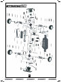
Transmitter
Preparing the transmitter
The function switches on the transmitter
1. Aerial
2. Throttle Trim
3. Steering Trim
4. Frequency Crystal
5. Throttle Trigger
6. Power Switch
7. Battery level indicator
8. Steering reverse switch
9. Throttle reverse switch
10. Steering Control (wheel)
1
8
9
7
6
10
2
3
4
5
Throttle/Steering Trim
Throttle Trim
1. Turn anti clockwise for more
brake
2. Turn clockwise for more
throttle
Steering Trim
1. Turn anti clockwise to trim to
the left
2. Turn clockwise to trim to the
right
1 2
1 2
Throttle Trigger
1. Push the trigger forward to
brake
2. Pull the trigger backwards to
go forwards and speed up
2
1
Neutral
Steering Wheel
Turn the steering wheel to the left
or right to make the go vehicle left
or right
L
R
Insert the aerial into
the hole and turn
clockwise until it is
tightly secured.
Open the battery holding
tray to expose the empty
battery slots.
Insert 8 AA batteries into
the marked spaces.
Please note the correct
direction of the batteries
Incorrect battery insertion
could lead to damage
Close the battery holding
tray to safely conceal and
secure the batteries.
Émetteur
Votre émetteur est un régulateur avancé conçu pour faciliter l’utilisation et le réglage pour le débutant. Vous devrez
suivre les étapes ci-dessous pour vous assurer que vous avez préparé correctement le régulateur et que vous avez
compris les possibilités disponibles de réglage.
Régulateur Accéléra-
tion / Direction
1 2
1 2
16
Insérez 8 piles AA dans les
espaces marqués à cet effet.
Veuillez faire attention au sens
correct des piles.
L’insertion incorrecte des piles
peut provoquer des dommages.
Préparation de l’émetteur
Insérez l’antenne dans le
trou et tournez-la à droite
jusqu’à ce qu’elle soit bien
fixe.
Assurez-vous de ne jamais
étendre l’antenne
excessivement pour ne pas
la casser.
Ouvrez la plaque de retenue des
piles pour découvrir les fentes
des piles vides.
1. Antenne
2. Régulateur d’accélérateur
3. Régulateur de direction
4. Élément piézoélectrique de
fréquence
5. Commande d’accélérateur
6. Contrôle de direction (roue)
7. Interrupteur
8. Indicateur de niveau des
piles
9. Commande de Direction
inverse
10. Commande
d’accélération inverse
11. Sélecteur de déviation
de direction
12. Sélecteur point limite de
direction (verrou gauche /
droite)
13. Sélecteur point limite
d’accélération (points
inférieur/ supérieur)
Les commandes de fonction de l’émetteur
6
2
3
1
4
5
8
9
7
10
11 12
13
Commande d’accélérateur
Roue directrice
2
1
Point mort
1. Tirez le déclencheur
vers l’avant pour freiner.
2. Tirez le déclencheur
vers l’arrière pour aller
vers l’avant et accélérer.
L
R
Tournez la roue
directrice vers la
gauche ou la droite
pour que le véhicule
aille dans cette
direction.
Régulateur d’accélérateur
1. Tournez vers la gauche pour
freiner plus fort.
2. Tournez vers la droite pour
accélérer plus fort.
Régulateur de direction
1. Tournez vers la gauche pour
orienter vers la gauche.
2. Tournez vers la droite pour
orienter vers la droite.
Sélecteur de réglage de point limite
La direction et l’accélération ont des points de réglage élevés
qui vous permettent d’ajuster le braquage de direction vers la
gauche et la droite et les points d’accélération élevés ou
faibles. Vous pouvez aussi régler le verrouillage général du
véhicule après le réglage de vos verrouillages latéraux
individuels.
Tous ces sélecteurs de réglage demande un mouvement vers
la gauche pour augmenter et un vers la droite pour diminuer.

Mesures de sécurité
Ce produit est un vrai véhicule radiocommandé et ce n’est pas un jouet. Lisez avec attention ce manuel
d’instructions avant de mettre le modèle en marche. Si vous n’êtes pas familiarisé avec les véhicules
radiocommandés, nous vous recommandons de demander le conseil pour qui cela est familier.
Ne connectez jamais la batterie de traction rechargeable en inversant les pôles ni ne démontez la batterie. Si la
batterie de traction est utilisée en sens inverse, un courant élevé peut être engendré et cela est très dangereux.
Ne mettez jamais des modèles radiocommandés en marche près de personnes ou d’animaux, ou dans des lieux
publics. Cela peut provoquer des accidents sérieux, des blessures, et/ou des dommages matériels.
Outils recommandés
Ces outils ne sont pas fournis avec le produit mais leur utilisation est recommandée pour travailler avec ce véhicule
Ciseaux, mini tournevis, Pinces a bec effile, Tounevis hexagonaux 1.5mm, 2.0mm, 2.5mm, 3.0mm, Cle en croix
(petite), Cle en croix (grande), Pinces coupantes de cote.
Charge du bloc- piles
Utilisez toujours le chargeur fourni pour le bloc de piles fourni. N’utilisez pas d’autres blocs de piles. Le temps de
chargement pour un bloc de piles vide est d’environ 6 heures. Ne chargez pas le bloc de pile pendant plus de 6
heures pour éviter la surchauffe et l’endommagement des piles.
Attention
• Ce chargeur ne peut être utilisé que pour le bloc de piles fourni dans ce jeu.
• Ne chargez pas le bloc piles pendant plus de 6 heures. La surchauffe engendre un excès de chaleur qui
endommagera le bloc-piles.
• Utilisez le chargeur sous la supervision d’un adulte. N’utilisez pas le chargeur près de l’eau ou s’il est mouillé.
• N’utilisez pas le chargeur si le câble est effiloché ou usé. Si le câble est effiloché ou usé, un court-circuit peut
provoquer un incendie ou des flammes.
• Si vous n’êtes pas sûr du niveau du bloc –piles avant de le charger, utilisez-le dans le véhicule jusqu’à ce qu’il
ralentisse, laissez-le refroidir puis rechargez.
Pendant la charge de votre bloc-piles, veuillez lire la partie suivante sur la conduite.
17

Conduite
La conduite d’une voiture radiocommandée peut être très difficile à maîtriser mais voici certains trucs de base pour
vous aider à comprendre comment l’utiliser avant votre première tentative.
• Conduisez le véhicule dans un endroit très grand, jusqu’à ce que vous ressentiez la conduite de ce produit.
• Ne mettez pas en marche dans des endroits ou voies publics. Cela peut provoquer des accidents sérieux, des
blessures, et/ou des dommages matériels.
• Ne faites pas marcher dans le sable ou l’eau.
• Vérifiez que chacun utilise des fréquences différentes pour conduire ensemble dans un même endroit.
• Si vous maintenez le déclencheur d’accélération de l’émetteur, le véhicule accélérera de plus en plus et ira
très vite. Il est difficile de manœuvrer le véhicule à grande vitesse jusqu’à ce que vous utilisiez l’entraînement.
Conduisez doucement le véhicule en tirant le déclencheur d’accélération à fond et en le relâchant aussitôt.
Vous pouvez faire tourner le véhicule à droite ou à gauche pendant son fonctionnement.
Lorsque le véhicule avance vers vous, vous devez mettre la roue directrice en sens inverse à sa marche lorsque il
s’éloigne de vous.
Exercez-vous à faire virer le véhicule en vous reportant à ce qui suit :
Plutôt que de ne prêter attention qu’au sens de la roue directrice, imaginez que vous êtes au centre de la roue
directrice, en regardant face au véhicule pour tourner dans le sens que vous souhaitez.
Une fois que vous vous sentez à l’aise pour
conduire le véhicule, exercez-vous à conduire
sur une piste avec des cônes.
Continuez à pratiquer jusqu’à ce que vous
vous sentiez à l’aise avec la direction,
l’accélération et le frein à de basses vitesses.
Une fois que vous êtes à l’aise, essayez en
marche arrière.
Lorsque vous maîtrisez les bases, vous serez
capable de conduire à de plus grandes
vitesses d’un mode contrôlé.
18

19
Installation du bloc -piles
1. Vous devez insérer le bloc-piles dans la partie
ouverte de la batterie. Utilisez la barrette fournie
pour mettre sur les piles, puis utilisez les deux
agrafes de retenue pour assurer les piles.
2. Une fois serrée et assurée, veuillez connecter la
fiche de la batterie dans la fiche du régulateur de
vitesse Vérifiez l’exactitude de la polarité. Rouge
avec rouge, noir avec noir.
Mise en marche
Posez le véhicule sur le bloc pour éviter que les roues ne touchent le sol
Allumez d’abord l’émetteur puis le récepteur.
Allumez l’émetteur et l’indicateur de batterie Del s’allume.
S’il clignote ou ne s’allume pas, vérifiez les polarités et l’alimentation des piles.
Si l’énergie des piles est faible, remplacez les piles par des neuves.
Sortez l’antenne à sa longueur maximale.
Allumez le récepteur. La configuration automatique du contrôle de vitesse ajusté en usine
devra être finie. Si vous rencontrez des problèmes avec les paramètres de contrôle de la
vitesse, reportez-vous à la partie de Contrôle de vitesse électronique pour une information
adéquate de configuration.
Si les pneus avant ne sont pas orientés vers l’avant avec l’émetteur en marche, ajustez le
régulateur de direction. Puis au besoin, effectuez des réglages plus précis avec le régulateur
de direction tout en conduisant le véhicule.
Si les roues vont vers la gauche,
tournez à droite.
Si les roues vont vers la droite,
tournez à gauche.
Si elles vont tout droit, aucun
réglage n’est à réaliser.

Arrêt
Éteignez d’abord le récepteur puis l’émetteur.
Si vous éteignez l’émetteur avant la voiture radiocommandée, vous pouvez perdre le contrôle de la voiture.
• Éteignez l’interrupteur du récepteur.
• Éteignez l’interrupteur de l’émetteur et baissez l’antenne.
• Déconnectez le connecteur des piles du connecteur de contrôle de vitesse.
Vérifiez d’éteindre toujours l’alimentation dans cet ordre (ordre inverse d’allumage). Si vous éteignez l’alimentation
dans l’ordre incorrect, le véhicule peut avancer sans contrôle et cela peut s’avérer très dangereux.
Déconnectez toujours le connecteur des piles du connecteur de contrôle de vitesse après avoir conduit.
Entretien après la conduite
Un entretien adéquat est très important. Réalisez toujours un entretien adéquat après la conduite pour que vous
puissiez profiter de la conduite sans aucun problème la fois suivante.
Enlevez complètement toute saleté et tout débris du véhicule, surtout des suspensions, des arbres de transmission
et des pièces de direction. Inspectez chaque pièce et vis contre tout desserrement, absence ou dommages.
Vous devrez toujours vérifier que vos roues sont bien serrées et que les pièces possèdent un mouvement libre avant
et après chaque utilisation.
Dépannage
Veuillez lire cette partie si vous rencontrez un défaut en essayant de faire marcher votre véhicule.
Si vous rencontrez un autre défaut lors du fonctionnement du véhicule, veuillez prendre contact avec votre magasin
de modélisme local ou avec notre distributeur local.
20
Problème Cause Solution
Le véhicule ne bouge pas
Le véhicule ne suit pas vos
commandes de conduite
L’émetteur ou le récepteur est
éteint
Les piles ne sont pas correcte-
ment installées dans l’émetteur
La batterie principale n’est pas
assez chargée
L’émetteur ou le récepteur est
éteint
L’antenne de l’émetteur ou du
récepteur n’est pas complètement
sortie
Une autre personne utilise la
même fréquence que vous
Allumez l’émetteur et le récepteur
Mettez correctement les piles dans
l’émetteur
Chargez la batterie principale
Allumez l’émetteur et le récepteur
Sortez complètement les deux
antennes
Changez vos éléments piézo
électriques de fréquence à un que
personne d’autre n’utilise ou
attendez que le conducteur de la
même fréquence ait fini de conduire
ou allez à un autre endroit pour
conduire votre véhicule
Les roues avant et arrière
tournent dans des directions
opposées
Emplacement différentiel de
l’usager incorrect
Insérez dans le bon sens le
différentiel
Seite wird geladen ...
Seite wird geladen ...
Seite wird geladen ...
Seite wird geladen ...
Seite wird geladen ...
Seite wird geladen ...
Seite wird geladen ...
Seite wird geladen ...
Seite wird geladen ...
Seite wird geladen ...
Seite wird geladen ...
Seite wird geladen ...
Seite wird geladen ...
Seite wird geladen ...
Seite wird geladen ...
Seite wird geladen ...
Seite wird geladen ...
Seite wird geladen ...
Seite wird geladen ...
Seite wird geladen ...
Seite wird geladen ...
Seite wird geladen ...
Seite wird geladen ...
Seite wird geladen ...
Seite wird geladen ...
Seite wird geladen ...
Seite wird geladen ...
Seite wird geladen ...
Seite wird geladen ...
Seite wird geladen ...
Seite wird geladen ...
Seite wird geladen ...
-
 1
1
-
 2
2
-
 3
3
-
 4
4
-
 5
5
-
 6
6
-
 7
7
-
 8
8
-
 9
9
-
 10
10
-
 11
11
-
 12
12
-
 13
13
-
 14
14
-
 15
15
-
 16
16
-
 17
17
-
 18
18
-
 19
19
-
 20
20
-
 21
21
-
 22
22
-
 23
23
-
 24
24
-
 25
25
-
 26
26
-
 27
27
-
 28
28
-
 29
29
-
 30
30
-
 31
31
-
 32
32
-
 33
33
-
 34
34
-
 35
35
-
 36
36
-
 37
37
-
 38
38
-
 39
39
-
 40
40
-
 41
41
-
 42
42
-
 43
43
-
 44
44
-
 45
45
-
 46
46
-
 47
47
-
 48
48
-
 49
49
-
 50
50
-
 51
51
-
 52
52


Maverick Strada SC Benutzerhandbuch
- Kategorie
- Ferngesteuertes Spielzeug
- Typ
- Benutzerhandbuch
in anderen Sprachen
- English: Maverick Strada SC User manual
- français: Maverick Strada SC Manuel utilisateur
- español: Maverick Strada SC Manual de usuario

