SICK WT12L-2 Photoelectric Proximity Sensor Bedienungsanleitung
- Kategorie
- Spielzeuge
- Typ
- Bedienungsanleitung

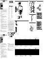
WT12L-2
A
!
B
$
§
"
-------------------------------------------------------------------------------- 8015869.10DC 1218 COMAT ----------------------------------------------------------------------------
ENGLISH
Photoelectric Proximity Sensor
with laser light
Operating Instructions
EN/IEC 60825-1:2014
IEC60825-1:2007
Maximum pulse power < 5,0 mW
Puls length: 4 µs
Wavelength: 650 - 670 nm
Complies with 21 CFR 1040.10
and 1040.11 except for deviations
pursuant to Laser Notice No. 50,
dated June 24, 2007
Laser Radiation
DO NOT STARE INTO BEAM
CLASS 2 LASER PRODUCT
Laser
2
• No safety component in accordance with EU machine guidelines.
• Read the operating instructions before starting operation.
• Connection, assembly, and settings only by competent technicians.
• Protect the device against moisture and soiling when operating.
• CAUTION: Use of controls or adjustments or performance of pro-
cedures other than those specied herein may result in hazardous
radiation exposure.
Proper Use
The photoelectric proximity sensor WT12L-2 is an optoelectronic
sensors used to optically detect objects.
Starting Operation
!
L: light-switching; if light received, output (Q) switches.
D: dark-switching; if light interrupted, output (Q) switches;
Select desired operating mode externally and connect as per con-
nection diagram B (L/D = control wire).
L/D after 0 = light-switching
L/D after L+ = dark-switching
"
The following apply for connection in B: brn = brown, blu = blue,
blk = black, gra = gray, wht = white.
Connect cables.
§
Mount photoelectric proximity sensor to suitable holders
(e.g. SICK mounting bracket).
Maintain direction in which object moves relative to sensor.
Connect photoelectric proximity sensor to operating voltage
(see type label).
Check application conditions such as sensing distance, object
size and background, and compare with characteristic in diagram.
(y = sensing distance displacement, x = sensing distance,
a = beam spot diameter).
$
Adjustment of light reception: Position object. Position light spot
on object, red sender light spot visible on object. Signal strength
indicator should light up. If it does not light up or if it ashes, re-
adjust and/or clean photoelectric proximity sensor and/or check
application conditions.
Remove object, signal strength indicator should go out. If it does
not go out or if it ashes, check and readjust application condi-
tions.
Maintenance
SICK photoelectric sensors do not require any maintenance. We
recommend that you clean the external lens surfaces and check the
screw connections and plug-in connections at regular intervals.
DEUTSCH
Reexions-Lichttaster
mit Laserlicht
Betriebsanleitung
EN/IEC 60825-1:2014
IEC60825-1:2007
Laser Radiation
DO NOT STARE INTO BEAM
CLASS 2 LASER PRODUCT
Laser
2
Maximale Pulsleistung: < 5,0 mW
Impulsdauer: 4 µs
Wellenlänge: 650 - 670 nm
Entspricht 21 CFR 1040.10
und 1040.11 mit Ausnahme von
Abweichungen nach
Laser-Hinweis 50, 24. Juni 2007
• Kein Sicherheitsbauteil gemäß EU-Maschinenrichtlinie.
• Vor der Inbetriebnahme die Betriebsanleitung lesen.
• Anschluss, Montage und Einstellung nur durch Fachpersonal.
• Gerät bei Inbetriebnahme vor Feuchte und Verunreinigung schützen.
Bestimmungsgemäße Verwendung
Der Reexions-Lichttaster WT12L-2 ist ein optoelektronischer Sensor
und wird zum optischen Erfassen von Sachen eingesetzt.
Inbetriebnahme
!
L: hellschaltend, bei Lichtempfang schaltet Ausgang (Q);
D: dunkelschaltend, bei Lichtunterbrechung schaltet Ausgang (Q).
Gewünschte Betriebsart extern wählen und laut Anschlussschema
B anschließen (L/D = Steuerleitung).
L/D nach 0 = hellschaltend
L/D nach L+ = dunkelschaltend
"
Leitungsdose spannungsfrei aufstecken und festschrauben.
Für Anschluss in B gilt: brn = braun, blu = blau, blk = schwarz,
gra = grau, wht = weiß.
Leitungen anschließen.
§
Lichttaster mit Befestigungsbohrungen an geeignete Halter
montieren (z. B. SICK-Haltewinkel).
Bewegungsrichtung des Objektes relativ zum Taster einhalten.
Lichttaster an Betriebsspannung legen (s. Typenaufdruck).
Einsatzbedingungen wie Tastweite, Objektgröße und Hinter-
grundeinuss überprüfen und mit der Kennlinie im Diagramm
ver gleichen (y = Tastweitenverschiebung, x = Tastweite, a = Licht-
eckgröße).
$
Justage Lichtempfang:
Objekt positionieren. Lichteck auf Objekt ausrichten, sichtbarer
roter Sendelichteck auf Objekt erkennbar. Empfangsanzeige
muss permanent leuchten. Leuchtet sie nicht oder blinkt sie,
Lichttaster neu justieren, reinigen bzw. Einsatzbedingungen
überprüfen.
Objekt entfernen, die Empfangsanzeige muss erlöschen. Erlöscht
sie nicht oder blinkt sie, Einsatzbedingungen überprüfen und neu
justieren.
Wartung
Dieser SICK-Lichttaster ist wartungsfrei. Wir empfehlen, in regel-
mäßigen Abständen
– die optischen Grenzächen zu reinigen,
– Verschraubungen und Steckverbindungen zu überprüfen.
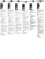
WT12 L-2 -B 510 -B 530 -B 540 -B 550
Sensing range TW Tastweite TW Distance de détection TW Raio de exploração TW 30 ... 200 mm
Focus Fokus Foyer Foco – 45 mm 80 mm 100 mm
Sensing range, fixed 6 %, focus 45 mm Tastbereich, fix, 6 %, Fokus 45 mm Plage de détection, fixe, 6 %, foyer 45 mm Área sensora, fix, 6 %, foco 45 mm 20 ... 50 mm
Light spot diameter/focusing point Lichtfleckdurchmesser/Fokuslage Diamètre de la tache lumineuse/Position du foyer Diâmetro do ponto de luz/Posição do foco 0,1 mm 0,1 mm 0,2 mm 0,2 mm
Supply voltage V
S
Versorgungsspannung U
V
Tension d'alimentation U
V
Tensão de força U
V
10 ... 30 V DC
1)
Output current I
max
Ausgangsstrom I
max.
Courant de sortie I
maxi
Corrente de saida I
máx.
100 mA
Signal sequence Signalfolge Fréquence Sequência min. de sinais 2500/s
Response time Ansprechzeit Temps de réponse Tempo de reação 200 µs
Enclosure rating Schutzart Type de protection Tipo de proteção IP 67
Protection class Schutzklasse Classe de protection Classe de proteção \
2)
Circuit protection
3)
Schutzschaltungen
3)
Circuits de protection
3)
Circuitos protetores
3)
A,B,C
Ambient operating temperature Betriebsumgebungstemperatur Température ambiante Temperatura ambiente de operação –10 … +50 °C
1)
Limits
Residual ripple max. 5 V
PP
2)
Reference voltage 50 V DC
3)
A = V
S
connections reverse polarity protected
B = outputs protected against short circuits
C = interference pulse suppression
1)
Grenzwerte
Restwelligkeit max. 5 V
SS
2)
Bemessungsspannung 50 V DC
3)
A = U
V
-Anschlüsse verpolsicher
B = Ausgänge kurzschlussfest
C = Störimpulsunterdrückung
1)
Valeurs limites
Ondulation résiduelle maxi 5 V
SS
2)
Tension de calcul 50 V c.c.
3)
A = Raccordements U
V
protégés contre les inversions de
polarité
B = Sorties protégées contre les courts-circuits
C = Suppression des impulsions
1)
Valores limite/ondulação
residual máx. 5 V
SS
2)
Tensão de dimensionamento 50 V DC
3)
A = Conexões U
V
protegidas contra inversão de polos
B = Saídas protegidas contra curto circuito
C = Supressão de impulsos parasitas
WT12 L-2 -B 510 -B 530 -B 540 -B 550
Portata di ricezione TW Alcance de palpación TW
探测距离 TW 検出範囲 TW
30 ... 200 mm
Fuoco Foco
焦点 焦点
– 45 mm 80 mm 100 mm
Ambito di rilevamento fisso, 6 %, fuoco 45 mm Zona de detección, fija, 6 %, foco 45 mm
测试域,不变,6 %,焦点 45 mm 検出範囲、固定、6 %、焦点 45 mm
20 ... 50 mm
Diametro punto/Posizione del fuoco Diámetro/Posición del foco
光点直径 / 距离焦点位置 スポット径/焦点位置
0,1 mm 0,1 mm 0,2 mm 0,2 mm
Tensione di alimentazione U
V
Tensión de alimentación U
V
电源电压 供給電圧 U
V
10 ... 30 V DC
1)
Corrente di uscita max. I
max.
Corriente de salida I
max.
输出电流 I
max
最大出力電流 I
max.
100 mA
Sequenza signali min. Secuencia de señales min.
信号流 min 信号伝達時間
2500/s
Tempo di risposta Tiempo de reacción
触发时间 応答時間
200 µs
Tipo di protenzione Tipo de protección
保护种类 保護等級
IP 67
Classe di protezione Protección clase
保护级别 保護クラス
\
2)
Commutazioni di protezione
3)
Circuitos de protección
3)
保护电路
3)
保護回路
3)
A,B,C
Temperatura ambiente circostante Temperatura ambiente de servicio
工作环境-温度 動作周囲温度
–10 … +50 °C
1)
Valori limite ondulatione
residua max. 5 V
SS
2)
Tensione di taratura 50 V DC
3)
A = U
V
-collegamenti con protez. contro inversione di poli
B = uscite a prova di corto circuito
C = soppressione impulsi di disturbo
1)
Valores límite
ondulación residual max. 5 V
SS
2)
Tensión tolerable 50 V DC
3)
A = Conexiones U
V
a prueba de inversión de polaridad
B = Salidas de resistentes al cortocircuito
C = Represión de impulso de interferencia
1)
极限值剩余波纹度 max. 5 V
SS
2)
限定电压 50 V DC
3)
A = U
V
-接头防反接
B = 输出端抗过流-及短路.
C = 消除干扰脉冲
1)
限界値
リップル 最大 5 V
PP
2)
基準電圧 50 V DC
3)
A = V
S
電源電圧逆接保護
B = 出力回路逆接保護
C = 干渉パルス抑制
More representatives and agencies at www.sick.com ∙ Subject to change
without notice ∙ The specied product features and technical data do not
represent any guarantee.
Weitere Niederlassungen nden Sie unter www.sick.com ∙ Irrtümer
und Änderungen vorbehalten ∙ Angegebene Produkteigenschaften und
technische Daten stellen keine Garantieerklärung dar.
Plus de représentations et d’agences à l’adresse www.sick.com ∙ Sujet à
modication sans préavis ∙ Les caractéristiques de produit et techniques
indiquées ne constituent pas de déclaration de garantie.
Para mais representantes e agências, consulte www.sick.com ∙ Alterações
poderão ser feitas sem prévio aviso ∙ As características do produto e os
dados técnicos apresentados não constituem declaração de garantia.
Altri rappresentanti ed agenzie si trovano su www.sick.com ∙ Contenuti
soggetti a modiche senza preavviso ∙ Le caratteristiche del prodotto e i dati
tecnici non rappresentano una dichiarazione di garanzia.
Más representantes y agencias en www.sick.com ∙ Sujeto a cambio sin
previo aviso ∙ Las características y los datos técnicos especicados no
constituyen ninguna declaración de garantía.
欲了解更多代表机构和代理商信息,请登录 www.sick.com ∙
如有更改, 不另行通知 ∙ 对所给出的产品特性和技术参数
的正确性不予保证。
その他の営業所はwww.sick.com よりご覧ください ・ 予告なしに変更され
ることがあります ・ 記載されている製品機能および技術データは保証を明
示するものではありません。
------------------------------------------------------------------------------------------------------------------------- -------------------------------------------------------------------------------------------------------------------------
30.1 (1.19)
16.2
(0.64)
24 (0.94)
10
(0.39)
41.5 (1.63)
49 (1.93)
11.2
(0.44)
22.6
(0.89)
5.6
(0.22)
7.3
(0.29)
2
(0.08)
5.1
(0.20)
16.5
(0.65)
15
(0.59)
1
L+
M
Q
P
3
4
brn
blu
blk
Q
N
2
wht
L/D
5
gra
a [mm]
x [mm]
-B 550
-B 530
-B 540
y [%]
x [mm]
BZ int48
Please find detailed addresses and further locations in all major industrial
nations at www.sick.com
Australia
Phone +61 (3) 9457 0600
Austria
Phone +43 (0) 2236 62288-0
Belgium/Luxembourg
Phone +32 (0) 2 466 55 66
Brazil
Phone +55 11 3215-4900
Canada
Phone +1 905.771.1444
Czech Republic
Phone +420 2 57 91 18 50
Chile
Phone +56 (2) 2274 7430
China
Phone +86 20 2882 3600
Denmark
Phone +45 45 82 64 00
Finland
Phone +358-9-25 15 800
France
Phone +33 1 64 62 35 00
Germany
Phone +49 (0) 2 11 53 01
Hong Kong
Phone +852 2153 6300
Hungary
Phone +36 1 371 2680
India
Phone +91-22-6119 8900
Israel
Phone +972-4-6881000
Italy
Phone +39 02 27 43 41
Japan
Phone +81 3 5309 2112
Malaysia
Phone +603-8080 7425
Mexico
Phone +52 (472) 748 9451
Netherlands
Phone +31 (0) 30 229 25 44
New Zealand
Phone +64 9 415 0459
Norway
Phone +47 67 81 50 00
Poland
Phone +48 22 539 41 00
Romania
Phone +40 356-17 11 20
Russia
Phone +7 495 283 09 90
Singapore
Phone +65 6744 3732
Slovakia
Phone +421 482 901 201
Slovenia
Phone +386 591 78849
South Africa
Phone +27 (0)11 472 3733
South Korea
Phone +82 2 786 6321
Spain
Phone +34 93 480 31 00
Sweden
Phone +46 10 110 10 00
Switzerland
Phone +41 41 619 29 39
Taiwan
Phone +886-2-2375-6288
Thailand
Phone +66 2 645 0009
Turkey
Phone +90 (216) 528 50 00
United Arab Emirates
Phone +971 (0) 4 88 65 878
United Kingdom
Phone +44 (0)17278 31121
USA
Phone +1 800.325.7425
Vietnam
Phone +65 6744 3732
SICK AG, Erwin-Sick-Strasse 1, D-79183 Waldkirch
2006/42/EG
NO
SAFETY
Seite wird geladen ...
-
 1
1
-
 2
2


SICK WT12L-2 Photoelectric Proximity Sensor Bedienungsanleitung
- Kategorie
- Spielzeuge
- Typ
- Bedienungsanleitung
in anderen Sprachen
- English: SICK WT12L-2 Photoelectric Proximity Sensor Operating instructions
- français: SICK WT12L-2 Photoelectric Proximity Sensor Mode d'emploi
- español: SICK WT12L-2 Photoelectric Proximity Sensor Instrucciones de operación
- italiano: SICK WT12L-2 Photoelectric Proximity Sensor Istruzioni per l'uso
- português: SICK WT12L-2 Photoelectric Proximity Sensor Instruções de operação
- 日本語: SICK WT12L-2 Photoelectric Proximity Sensor 取扱説明書
Verwandte Artikel
-
SICK WS/WE190L Standard Bedienungsanleitung
-
-
-
-
SICK WT23L-F430 Bedienungsanleitung
-
-
-
-
-