Burkert 6012 Operating Instructions Manual
- Typ
- Operating Instructions Manual

www.burkert.com
We reserve the right to make
technical changes without notice.
Technische Änderungen
vorbehalten.
Sous resérve de modification
techniques.
© 2008 - 2009 Bürkert Werke GmbH & Co. KG
Operating Instructions 0909/19_EU-ml_00803160
Solenoid valve
3/2-Way Mini Solenoid Valve
Operating Instructions
Bedienungsanleitung
Manuel d’utilisation
2
The operating instructions describe the entire life cycle of the
device. Keep these instructions in a location which is easily
accessible to every user and make these instructions available
to every new owner of the device.
The operating instructions contain important safety
information!
Failure to observe these instructions may result in haz-
ardous situations.
The operating instructions must be read and understood.•
english
3
The following symbols are used in these instructions.
Warns of an immediate danger!
Failure to observe the warning may result in a fatal or •
serious injury.
Warns of a potentially dangerous situation!
Failure to observe the warning may result in a serious or •
fatal injury.
Warns of a possible danger!
Failure to observe this warning may result in a medium •
or minor injury.
Warns of damage to property!
Important tips and recommendations.
designates a procedure which you must carry out.
→
english
3
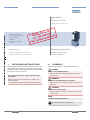
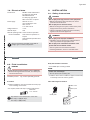
Voltage 12V or 24V
UL / UR valid with
class 2 power supply only

4
Incorrect use of the solenoid valve Type 6012 can
be dangerous to people, nearby equipment and the
environment.
The device is designed for blocking, dosing, filling and •
venting neutral gaseous and liquid media.
Do not use the device outdoors.•
Use according to the permitted data, operating condi-•
tions and conditions of use specified in the contract
documents and operating instructions. These are
described in the chapter entitled “7. Technical Data”.
The device may be used only in conjunction with third-•
party devices and components recommended and
authorised by Bürkert.
Correct transportation, correct storage and installation •
and careful use and maintenance are essential for reli-
able and problem-free operation.
Use the device only as intended.•
english
5
If exporting the system/device, observe any existing
restrictions.
The approval mark indicated on the Bürkert labels refers to
the Bürkert products.
e 1
03 5791
Devices which must bear the type approval mark were
approved at the Kraftfahrtbundesamt under the type
approval number
and are put into circulation with the indicated type approval
mark. You can obtain an extract of the type approval from
the address below.
Bürkert Werke GmbH
Zulassungsbeauftragter,
Christian-Bürkert-Str. 13-17,
D-74653 Ingelfingen
english
5
6
The solenoid valve Type 6012 is not to be used in areas •
where there is a risk of explosion.
Do not supply the medium connectors of the system with •
aggressive or flammable mediums.
Do not put any loads on the body (e.g. by placing objects •
on it or standing on it).
Do not make any external modifications to the device •
bodies. Do not paint the body parts or screws.
english
7
These safety instructions do not make allowance for any
contingencies and events which may arise during the •
installation, operation and maintenance of the devices.
local safety regulations – the operator is responsible for •
observing these regulations, also with reference to the
installation personnel.
Danger – high pressure!
Before loosening the lines and valves, turn off the •
pressure and vent the lines.
Risk of electric shock!
Before reaching into the system,• switch off the power
supply and secure to prevent reactivation!
Observe applicable accident prevention and safety •
regulations for electrical equipment!
Risk of burns/Risk of fire if used continuously
through hot device surface!
Keep the device away from highly flammable sub-•
stances and media and do not touch with bare hands.
english
7
Type 6012

8
General hazardous situations.
To prevent injury, ensure that:
the system cannot be activated unintentionally.•
Installation and repair work may be carried out by •
authorized technicians only and with the appropriate
tools.
After an interruption in the power supply or pneu-•
matic supply, ensure that the process is restarted in a
defined or controlled manner.
The device may be operated only when in perfect condi-•
tion and in consideration of the operating instructions.
The general rules of technology apply to application •
planning and operation of the device.
english
9
The solenoid valve Type 6012 was developed with due
consideration given to the accepted safety rules and is
state-of-the-art. However, dangers can still arise.
Failure to observe this operating manual and its operating
instructions as well as unauthorized tampering with the
device release us from any liability and also invalidate the
warranty covering the device and accessories!
english
9
10
Check immediately upon receipt of the delivery that the con-
tents are not damaged and that the type and scope agree
with the delivery note and packing list.
If there are any discrepancies, please contact us immediately.
Bürkert Fluid Control Systems
Sales Center
Chr.-Bürkert-Str. 13-17
D-74653 Ingelfingen
Tel.: +49 (0)7940 - 10 91 111
Fax: +49 (0)7940 - 10 91 448
E-mail: [email protected]
Contact addresses can be found on the final pages of the
printed operating instructions.
And also on the internet at:
www.burkert.com
Bürkert Company Locations
english
11
This document contains no promise or guarantee. Please refer
to our general terms of sales and delivery. The warranty is only
valid if the solenoid valve Type 6012 is used as authorized in
accordance with the specified application conditions.
The warranty extends only to defects in the solenoid
valve Type 6012 and its components.
We accept no liability for any kind of collateral
damage which can occur due to failure or malfunction
of the device.
The operating instructions and data sheets for Type 6012
can be found on the Internet at:
www.burkert.com
Documentation
english
11
Type 6012

12
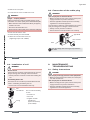
The direct-acting solenoid valve Type 6012 is available in
two designs.
Type 6012 is used for the blocking, dosing,
filling and venting of neutral gaseous and
liquid media, in particular for controlling
single-acting pneumatic drives or technical
vacuum. The modular designed valve can be
installed individually or in a block on the mul-
tiple manifold.
Type 6012P is used as a special pilot valve
for direct installation on the externally con-
trolled pneumatic drives. It consists of the
magnetic drive Type 6012 and a special
connection body with hollow screw which
can be connected directly to the control air
connection of the drive. The valve features
manual actuation as standard.
english
13
Risk of injury
Malfunction if used outside!
Do not use Type 6012 outdoors and avoid heat •
sources which may cause the allowable temperature
range to be exceeded.
Ambient temperature: -10 – +55 °C
Medium temperature: -10 – +100 °C
Media: neutral gaseous and liquid media
(e.g. compressed air, Water, Hydraulic
fluid, technical Vacuum)
Viscosity: max. 21 mm²/s
Protection class: IP65 in accordance with EN 60529 with
cable plug
CE mark conforms to EMC Directive 2004/108/EEC (pre-
viously: 89/336/EEC; only if cables, plugs and sockets
have been connected correctly).
english
13
14
Dimensions See data sheet
Body material Type 6012: Brass, polyamide (PA),
Stainless steel 1.4305
Type 6012P: Polyamide (PA)
Hollow screw Type 6012P: Brass, nickel-plated
Sealing material FKM / EPDM
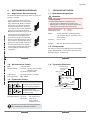
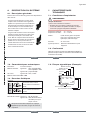
Circuit functions
C
(NC)
2(A)
1(P)
3(R)
3/2-way valve, direct-acting,
normal output A unloaded
D
(NO)
2(B)
1(P)
3(R)
3/2-way valve, direct-acting,
normal output B pressurized
Pressure range 0 – 16 bar
Line connectors Type 6012: M5, G1/8, Flange
Type 6012P: G1/8, G1/4
Hose connector ∅ 6 mm
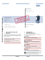
Note the information specified on the label for
voltage, type of current, and pressure.
english
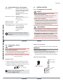
15
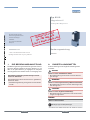
Ident. no.
Voltage/Frequency output
Nominal connection pressure
Type
Circuit function
Orifice
Sealing material
Body material
6012 C 1,2 FKM MS
Made in Germany
CE
00450000
WXXXX
24V 50Hz 4W
G1/8 PN 0
-
10 bar
english
15
Type 6012

16
Connections: DIN EN 175301-803 Form C
for cable plug Type 2506
DIN 43650 Form B
for cable plug Type 2507
Wire connection on request
Power supply: 24 V DC ± 10 % -
max. residual ripple 10%
24 V / 50 Hz
110 / 230 / 50 Hz
Voltage tolerance: ± 10%
Nominal output: 4 W
Nominal operating mode: 100% continuous operation
for block installation 2 W continuous operation on
request
4 W intermittent operation 60%
(30 min)
Note the information specified on the label for
voltage, type of current, and pressure.
english
17
Risk of injury from high pressure in the equipment!
Before loosening the lines and valves, turn off the •
pressure and vent the lines.
Risk of injury due to electrical shock!
Before reaching into the system, switch off the power •
supply and secure to prevent reactivation!
Observe applicable accident prevention and safety •
regulations for electrical equipment!
Risk of injury from improper installation!
Installation may be carried out by authorized techni-•
cians only and with the appropriate tools!
Risk of injury from unintentional activation of the
system and an uncontrolled restart!
Secure system from unintentional activation.•
Following installation, ensure a controlled restart.•
english
17
18
Risk of injury from high pressure in the equipment!
Before loosening the lines and valves, turn off the pres-•
sure and vent the lines.
Installation position: any, actuator preferably upwards.
Procedure:
Before installation, clean any possible dirt off the pipe-
→
lines and flange connections.
If required, install a dirt trap to prevent malfunctions.
→
Mesh size:
0.2 – 0.4 mm
Pay attention to the flow direction of the valve.
from 1(P) → 2(A) (CF C) or
from 1(P) → 2(B) (CF D)
english
19
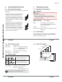
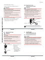
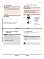
Body with threaded connection:
Use PTFE tape as sealing material
→
Caution risk of breakage!
Do not use the coil as a lifting arm.•
Hold the device with a suitable tool (Open-end wrench)
→
on the body and screw into the pipeline.
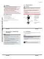
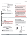
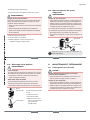
Valve with flanged connection:
Seal
Nut
Coil
Cover plate
english
19
Type 6012

20
Remove the cover plate. →
Loosen the nut on the coil and remove coil. →
Danger – escaping medium!
Leaking connections if seals not seated properly, if man-
ifold uneven or if surface quality of the manifold inadequate.
Make certain the seals included with delivery are properly •
seated in the valve.
Ensure that the manifold is even.•
Ensure that the surface quality of the manifold is adequate.•
Insert the seal into the valve.
→
Screw the body onto the manifold. →
Attach the coil and screw on the nut →
(Tightening torque: max. 2.8 Nm).
english
21
Risk of injury due to electrical shock!
Before reaching into the system, switch off the power •
supply and secure to prevent reactivation!
Observe applicable accident prevention and safety •
regulations for electrical equipment!
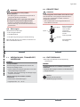
If the protective conductor contact between the coil and
body is missing, there is danger of electrical shock!
Always connect protective conductor.•
Check electrical continuity between coil and body.•
max. 0.30 Nm
Type 2506
Seal
Note the voltage and current type as specified on
the label.
english
21
22
Electric shock
If the protective conductor contact between the coil and
body is missing, there is danger of electrical shock!
Check protective conductor contact after installing the •
coil.
Overheating, Risk of fire
Connection of the coil without pre-assembled valve will
result in overheating and destroy the coil.
Connect the coil with assembled valve only.•
4 x 90°
Nut
max. 2.8 Nm
O-ring
The coil can be turned by
4 x 90°.
Loosen nut
→
Turn coil →
Tighten nut with →
suitable tool
(Open-end wrench)
(max. 2.8 Nm).
english
23
Risk of injury from high pressure in the equipment!
Before loosening the lines and valves, turn off the pres-•
sure and vent the lines.
Risk of injury due to electrical shock!
Before reaching into the system, switch off the power •
supply and secure to prevent reactivation!
Observe applicable accident prevention and safety •
regulations for electrical equipment!
english
23
Type 6012

24
Risk of injury from improper maintenance!
Maintenance may be carried out by authorized techni-•
cians only and with the appropriate tools!
Risk of injury from unintentional activation of the
system and an uncontrolled restart!
Secure system from unintentional activation.•
Following maintenance, ensure a controlled restart.•
If malfunctions occur, check
the line connectors
→
the operating pressure →
the power supply and valve control →
If the valve still does not switch, please contact your
Bürkert Service.
english
25
Risk of injury and/or damage by the use of incorrect
parts!
Incorrect accessories and unsuitable spare parts may
cause injuries and damage the device and the sur-
rounding area.
Use only original accessories and original spare parts •
from Bürkert.
Fitting
Coil
Nut
Coil and fitting can
be ordered com-
plete by quoting
the identification
number of the
device.
(see label)
Wearing part set on
request.
english
25
26
Transport damages!
Inadequately protected equipment may be damaged
during transport.
During transportation protect the device against wet •
and dirt in shock-resistant packaging.
Avoid exceeding or dropping below the allowable •
storage temperature.
Incorrect storage may damage the device.
Store the device in a dry and dust-free location!•
Storage temperature:• -40 - 80 °C.
english
27
Dispose of the device and packaging in an environmen- →
tally friendly manner.
Damage to the environment caused by device compo-
nents contaminated with media.
Observe applicable regulations on disposal and the •
environment.
Note:
Observe national waste disposal regulations.
english
27
Type 6012

www.burkert.com
We reserve the right to make
technical changes without notice.
Technische Änderungen
vorbehalten.
Sous resérve de modification
techniques.
© 2008 - 2009 Bürkert Werke GmbH & Co. KG
Operating Instructions 0909/19_EU-ml_00803160
Magnetventil
3/2-Wege-Mini-Magnetventil
Bedienungsanleitung
Deutsch
30
Die Bedienungsanleitung beschreibt den gesamten Lebens-
zyklus des Gerätes. Bewahren Sie diese Anleitung so auf,
dass sie für jeden Benutzer gut zugänglich ist und jedem
neuen Eigentümer des Gerätes wieder zur Verfügung steht.
Die Bedienungsanleitung enthält wichtige Informa-
tionen zur Sicherheit!
Das Nichtbeachten dieser Hinweise kann zu gefährlichen
Situationen führen.
Die Bedienungsanleitung muss gelesen und verstanden •
werden.
deutsch
31
In dieser Anleitung werden folgende Darstellungsmittel
verwendet.
Warnt vor einer unmittelbaren Gefahr!
Bei Nichtbeachtung sind Tod oder schwere Verletzun-•
gen die Folge.
Warnt vor einer möglicherweise gefährlichen Situation!
Bei Nichtbeachtung können schwere Verletzungen oder •
Tod die Folge sein.
Warnt vor einer möglichen Gefährdung!
Nichtbeachtung kann mittelschwere oder leichte Verlet-•
zungen zur Folge haben.
Warnt vor Sachschäden!
Wichtige Tipps und Empfehlungen.
markiert einen Arbeitsschritt den Sie ausführen müssen.
→
deutsch
Voltage 12V or 24V
UL / UR valid with
class 2 power supply only

32
Bei nicht bestimmungsgemäßem Einsatz des
Magnetventils Typ 6012 können Gefahren für Per-
sonen, Anlagen in der Umgebung und die Umwelt
entstehen.
Das Gerät ist zum Sperren, Dosieren, Füllen und •
Belüften von neutralen gasförmigen und flüssigen
Medien konzipiert.
Das Gerät nicht im Außenbereich einsetzen.•
Für den Einsatz die in den Vertragsdokumenten und •
der Bedienungsanleitung spezifizierten zulässigen
Daten, Betriebs- und Einsatzbedingungen beach-
ten. Diese sind im Kapitel „7. Technische Daten“
beschrieben.
Das Gerät nur in Verbindung mit von Bürkert empfoh-•
lenen bzw. zugelassenen Fremdgeräten und -kompo-
nenten einsetzen.
Voraussetzungen für den sicheren und einwandfreien •
Betrieb sind sachgemäßer Transport, sachgemäße
Lagerung und Installation sowie sorgfältige Bedienung
und Instandhaltung.
Setzen Sie das Gerät nur bestimmungsgemäß ein.•
deutsch
33
Beachten Sie bei der Ausfuhr des Systems/Gerätes gege-
benenfalls bestehende Beschränkungen.
Die auf den Bürkert Typschildern aufgebrachte Zulas-
sungskennzeichnung bezieht sich auf die Bürkert Produkte.
e 1
03 5791
Geräte, die das Typgenehmigungszeichen tragen
müssen, wurden beim Kraftfahrtbundesamt unter der
Typgenehmigungsnummer
genehmigt und werden mit dem gezeigten Typgenehmi-
gungszeichen in den Verkehr gebracht. Einen Auszug der
Typgenehmigung erhalten Sie unter der unten stehenden
Adresse.
Bürkert Werke GmbH
Zulassungsbeauftragter,
Christian-Bürkert-Str. 13-17,
D-74653 Ingelfingen
deutsch
34
Das Magnetventil Typ 6012 darf nicht in explosionsgefähr-•
deten Bereichen eingesetzt werden.
Speisen Sie in die Medienanschlüsse des Systems keine •
aggressiven oder brennbaren Medien ein.
Belasten Sie das Gehäuse nicht mechanisch (z.B. durch •
Ablage von Gegenständen oder als Trittstufe).
Nehmen Sie keine äußerlichen Veränderungen an den •
Gerätegehäusen vor. Gehäuseteile und Schrauben nicht
lackieren.
deutsch
35
Diese Sicherheitshinweise berücksichtigen keine
Zufälligkeiten und Ereignisse, die bei Montage, Betrieb •
und Wartung der Geräte auftreten können.
ortsbezogenen Sicherheitsbestimmungen, für deren •
Einhaltung, auch in Bezug auf das Montagepersonal, der
Betreiber verantwortlich ist.
Gefahr durch hohen Druck!
Vor dem Lösen von Leitungen und Ventilen den Druck •
abschalten und Leitungen entlüften.
Gefahr durch elektrische Spannung!
Vor Eingriffen in das System, Spannung abschalten •
und vor Wiedereinschalten sichern!
Die geltenden Unfallverhütungs- und Sicherheitsbe-•
stimmungen für elektrische Geräte beachten!
Verbrennungsgefahr/Brandgefahr bei Dauerbetrieb
durch heiße Geräteberfläche!
Das Gerät von leicht brennbaren Stoffen und Medien •
fernhalten und nicht mit bloßen Händen berühren.
deutsch
Type 6012

36
Allgemeine Gefahrensituationen.
Zum Schutz vor Verletzungen ist zu beachten:
Dass die Anlage nicht unbeabsichtigt betätigt werden •
kann.
Installations- und Instandhaltungsarbeiten dürfen nur •
von autorisiertem Fachpersonal mit geeignetem Werk-
zeug ausgeführt werden.
Nach einer Unterbrechung der elektrischen oder pneu-•
matischen Versorgung ist ein definierter oder kontrol-
lierter Wiederanlauf des Prozesses zu gewährleisten.
Das Gerät darf nur in einwandfreiem Zustand und •
unter Beachtung der Bedienungsanleitung betrieben
werden.
Für die Einsatzplanung und den Betrieb des Gerätes •
müssen die allgemeinen Regeln der Technik eingehal-
ten werden.
deutsch
37
Das Magnetventil Typ 6012 wurde unter Einbe-
ziehung der anerkannten sicherheitstechnischen
Regeln entwickelt und entspricht dem Stand der
Technik. Trotzdem können Gefahren entstehen.
Bei Nichtbeachtung dieser Bedienungsanleitung und ihrer
Hinweise sowie bei unzulässigen Eingriffen in das Gerät
entfällt jegliche Haftung unsererseits, ebenso erlischt die
Gewährleistung auf Geräte und Zubehörteile!
deutsch
38
Überzeugen Sie sich unmittelbar nach Erhalt der Sendung,
dass der Inhalt nicht beschädigt ist und in Art und Umfang mit
dem Lieferschein bzw. der Packliste übereinstimmt.
Bei Unstimmigkeiten wenden Sie sich bitte umgehend an
uns.
Bürkert Fluid Control Systems
Sales Center
Chr.-Bürkert-Str. 13-17
D-74653 Ingelfingen
Tel. : +49 (0) 7940 - 10 91 111
Fax: +49 (0) 7940 - 10 91 448
E-mail: [email protected]
Die Kontaktadressen finden Sie auf den letzten Seiten der
gedruckten Bedienungsanleitung.
Außerdem im Internet unter:
www.burkert.com
Bürkert Company Locations
deutsch
39
Diese Druckschrift enthält keine Garantiezusagen. Wir ver-
weisen hierzu auf unsere allgemeinen Verkaufs- und Liefer-
bedingungen. Voraussetzung für die Gewährleistung ist der
bestimmungsgemäße Gebrauch des Magnetventils Typ 6012
unter Beachtung der spezifizierten Einsatzbedingungen.
Die Gewährleistung erstreckt sich nur auf die Feh-
lerfreiheit des Magnetventils Typ 6012 und seiner
Bauteile.
Für Folgeschäden jeglicher Art, die durch Ausfall
oder Fehlfunktion des Gerätes entstehen könnten,
wird keine Haftung übernommen.
Bedienungsanleitungen und Datenblätter zum Typ 6012
finden Sie im Internet unter:
www.buerkert.de
Dokumentation
deutsch
Type 6012

40
Das direktwirkende Magnetventil Typ 6012 ist in zwei Aus-
führungen verfügbar.
Typ 6012 wird zum Sperren, Dosieren,
Füllen und Belüften von neutralen gasför-
migen und flüssigen Medien verwendet,
insbesondere zum Steuern einfachwir-
kender Pneumatikantriebe oder techni-
sches Vakuum. Das modular aufgebaute
Ventil kann einzeln oder im Block auf
Mehrfachanschlussplatte montiert werden.
Typ 6012P wird als spezielles Pilotventil
zum Direktanbau an fremdgesteuerte
pneumatische Antriebe verwendet. Es
besteht aus dem Magnetantrieb vom Typ
6012 und einem speziellen Anschluss-
gehäuse mit Hohlschraube, die direkt an
den Steuerluftanschluss des Antriebs
angeschlossen werden kann. Das Ventil
ist serienmäßig mit Handbetätigung
ausgestattet.
deutsch
41
Verletzungsgefahr
Funktionsausfall bei Einsatz im Außenbereich!
Typ 6012 nicht im Außenbereich einsetzen und •
Wärmequellen vermeiden, die zur Überschreitung des
zulässigen Temperaturbereichs führen können.
Umgebungstemperatur: -10 ... +55 °C
Mediumstemperatur: -10 ... +100°C
Medien neutrale gasförmige und flüssige Medien
(z. B. Druckluft, Wasser, Hydrauliköl, techni-
sches Vakuum)
Viskosität max. 21 mm²/s
Schutzart IP65 nach EN 60529 mit Gerätesteckdose
CE - Zeichen konform bzgl. EMV-Richtlinie 2004/108/EG
(bisher: 89/336/EWG; nur bei korrekt angeschlossenem
Kabel bzw. Stecker und Buchsen).
deutsch
42
Maße siehe Datenblatt
Gehäusematerial Typ 6012: Messing, Polyamid (PA),
Edelstahl 1.4305
Typ 6012P: Polyamid (PA)
Hohlschraube Typ 6012P : Messing, vernickelt
Dichtungsmaterial FKM / EPDM
Wirkungsweisen
C
(NC)
2(A)
1(P)
3(R)
3/2 Wege-Ventil, direktwirkend,
stromlos Ausgang A entlastet
D
(NO)
2(B)
1(P)
3(R)
3/2 Wege-Ventil, direkt-
wirkend, stromlos Ausgang B
druckbeaufschlagt
Druckbereich 0 ... 16 bar
Leitungsanschlüsse Typ 6012: M5, G1/8, Flansch
Typ 6012P: G1/8, G1/4
Schlauchsteck-
verbinder ∅ 6 mm
Beachten Sie die auf dem Typschild angegebene
Daten für Spannung, Stromart und Druck.
deutsch
43
Ident-Nr.
Spannung-Frequenz-Leistung
Anschluss-Nenndruck
Typ
Wirkungsweise
Nennweite
Dichtwerkstoff
Gehäusewerkstoff
6012 C 1,2 FKM MS
Made in Germany
CE
00450000
WXXXX
24V 50Hz 4W
G1/8 PN 0
-
10 bar
deutsch
Type 6012

44
Anschlüsse: DIN EN 175301-803 Form C
für Gerätesteckdose Typ 2506
DIN 43650 Form B
für Gerätesteckdose Typ 2507
Litzenanschluss auf Anfrage
Spannungsversorgung: 24 V DC ± 10 % -
max. Restwelligkeit 10 %
24 V / 50 Hz
110 / 230 / 50 Hz
Spannungstoleranz: ± 10 %
Nennleistung: 4 W
Nennbetriebsart: Dauerbetrieb, ED 100 %
bei Blockmontage 2 W Dauerbetrieb a. A.
4 W Aussetzbetrieb 60 %
(30 min)
Beachten Sie die auf dem Typschild angegebene
Daten für Spannung, Stromart und Druck.
deutsch
45
Verletzungsgefahr durch hohen Druck in der Anlage!
Vor dem Lösen von Leitungen und Ventilen den Druck •
abschalten und Leitungen entlüften.
Verletzungsgefahr durch Stromschlag!
Vor Eingriffen in das System die elektrische Spannung •
abschalten und vor Wiedereinschalten sichern!
Die geltenden Unfallverhütungs- und Sicherheitsbe-•
stimmungen für elektrische Geräte beachten!
Verletzungsgefahr bei unsachgemäßer Installation!
Die Installation darf nur autorisiertes Fachpersonal mit •
geeignetem Werkzeug durchführen!
Verletzungsgefahr durch ungewolltes Einschalten
der Anlage und unkontrollierten Wiederanlauf!
Anlage vor unbeabsichtigtem Betätigen sichern.•
Nach der Installation einen kontrollierten Wiederanlauf •
gewährleisten.
deutsch
46
Verletzungsgefahr durch hohen Druck in der Anlage!
Vor dem Lösen von Leitungen und Ventilen den Druck •
abschalten und Leitungen entlüften.
Einbaulage: beliebig, vorzugsweise Antrieb nach oben.
Vorgehensweise:
Vor der Montage Rohrleitungen und Flanschanschlüsse
→
von eventuellen Verschmutzungen säubern.
Zum Schutz vor Störungen gegebenenfalls einen
→
Schmutzfänger einbauen.
Maschenweite:
0,2 ... 0,4 mm
Beachten Sie die Durchflussrichtung des Ventils.
von 1(P) → 2(A) (WW C) oder
von 1(P) → 2(B) (WW D)
deutsch
47
Gehäuse mit Gewindeanschluss:
Als Dichtungsmaterial PTFE-Band verwenden.
→
Vorsicht Bruchgefahr!
Die Spule darf nicht als Hebelarm benutzt werden.•
Das Gerät mit geeignetem Werkzeug (Gabelschlüssel)
→
am Gehäuse festhalten und in die Rohrleitung
einschrauben.
Ventil mit Flanschanschluss:
Dichtung
Mutter
Spule
Verschlussplatte
deutsch
Type 6012

48
Die Verschlussplatte entfernen. →
Mutter der Spule lösen und Spule demontieren. →
Gefahr durch Mediumsaustritt!
Undichte Anschlüsse bei ungenauem Sitz der Dichtungen,
bei unebener Anschlussplatte oder unzureichender Ober-
flächengüte der Anschlussplatte.
Achten Sie bei den mitgelieferten Dichtungen auf den •
richtigen Sitz im Ventil.
Achten Sie auf die Ebenheit der Anschlussplatte.•
Achten Sie auf ausreichende Oberflächengüte der •
Anschlussplatte.
Die Dichtung in das Ventil einlegen.
→
Das Gehäuse auf die Anschlussplatte schrauben. →
Spule aufstecken und die Mutter befestigen →
(Anzugsmoment: max. 2,8 Nm).
deutsch
49
Verletzungsgefahr durch Stromschlag!
Vor Eingriffen in das System die elektrische Spannung •
abschalten und vor Wiedereinschalten sichern!
Die geltenden Unfallverhütungs- und Sicherheitsbe-•
stimmungen für elektrische Geräte beachten!
Bei fehlendem Schutzleiterkontakt zwischen Spule und
Gehäuse besteht die Gefahr des Stromschlags!
Schutzleiter immer anschließen.•
Elektrischer Durchgang zwischen Spule und Gehäuse •
prüfen.
max. 0,30 Nm
Typ 2506
Dichtung
Spannung und Stromart laut Typschild beachten.
deutsch
50
Stromschlag
Bei fehlendem Schutzleiterkontakt zwischen Spule und
Gehäuse besteht die Gefahr des Stromschlags!
Schutzleiterkontakt nach der Spulenmontage prüfen.•
Überhitzung, Brandgefahr
Der Anschluss der Spule ohne vormontiertes Ventil führt
zur Überhitzung und zerstört die Spule.
Spule nur mit montiertem Ventil anschließen.•
4 x 90°
Mutter
max. 2,8 Nm
O-Ring
Die Spule kann um 4 x 90°
verdreht werden.
Mutter lösen
→
Spule verdrehen →
Mutter mit geeignetem →
Werkzeug (Gabel-
schlüssel) festdrehen
(max. 2,8 Nm).
deutsch
51
Verletzungsgefahr durch hohen Druck in der Anlage!
Vor dem Lösen von Leitungen und Ventilen den Druck •
abschalten und Leitungen entlüften.
Verletzungsgefahr durch Stromschlag!
Vor Eingriffen in das System die elektrische Spannung •
abschalten und vor Wiedereinschalten sichern!
Die geltenden Unfallverhütungs- und Sicherheitsbe-•
stimmungen für elektrische Geräte beachten!
deutsch
Type 6012

52
Verletzungsgefahr bei unsachgemäßen
Wartungsarbeiten!
Die Wartung darf nur autorisiertes Fachpersonal mit •
geeignetem Werkzeug durchführen!
Verletzungsgefahr durch ungewolltes Einschalten
der Anlage und unkontrollierten Wiederanlauf!
Anlage vor unbeabsichtigtem Betätigen sichern.•
Nach der Wartung einen kontrollierten Wiederanlauf •
gewährleisten.
Überprüfen Sie bei Störungen
die Leitungsanschlüsse
→
den Betriebsdruck →
die Spannungsversorgung und Ventilansteuerung →
Falls das Ventil dennoch nicht schaltet, wenden Sie sich
bitte an Ihren Bürkert-Service.
deutsch
53
Verletzungsgefahr, Sachschäden durch falsche Teile!
Falsches Zubehör und ungeeignete Ersatzteile können
Verletzungen und Schäden am Gerät und dessen
Umgebung verursachen
Nur Originalzubehör sowie Originalersatzteile der •
Firma Bürkert verwenden.
Armatur
Spule
Mutter
Spule und Armatur
können komplett
unter der Ident-
nummer des
Gerätes bestellt
werden.
(siehe Typschild)
Verschleißteilsatz
auf Anfrage.
deutsch
54
Transportschäden!
Unzureichend geschützte Geräte können durch den
Transport beschädigt werden.
Gerät vor Nässe und Schmutz geschützt in einer stoß-•
festen Verpackung transportieren.
Eine Über- bzw. Unterschreitung der zulässigen Lager-•
temperatur vermeiden.
Falsche Lagerung kann Schäden am Gerät
verursachen.
Gerät trocken und staubfrei lagern!•
Lagertemperatur:• -40 … 80 °C.
deutsch
55
Entsorgen Sie das Gerät und die Verpackung →
umweltgerecht.
Umweltschäden durch von Medien kontaminierte
Geräteteile.
Geltende Entsorgungsvorschriften und Umweltbestim-•
mungen einhalten.
Hinweis:
Beachten Sie die nationalen
Abfallbeseitigungsvorschriften.
deutsch
Type 6012

www.burkert.com
We reserve the right to make
technical changes without notice.
Technische Änderungen
vorbehalten.
Sous resérve de modification
techniques.
© 2008 - 2009 Bürkert Werke GmbH & Co. KG
Operating Instructions 0909/19_EU-ml_00803160
Électrovanne
Électrovanne mini à 3/2 voies
Manuel d’utilisation
Français
58
Les instructions de service décrivent le cycle de vie complet
de l’appareil. Conservez ces instructions de sorte qu’elles
soient accessibles à tout utilisateur et à disposition de tout
nouveau propriétaire.
Les instructions de service contiennent des informa-
tions importantes sur la sécurité !
Le non-respect de ces consignes peut entraîner des
situations dangereuses.
Les instructions de service doivent être lues et comprises.•
français
59
Les moyens de représentation suivants sont utilisés dans
les présentes instructions de service.
Met en garde contre un danger imminent !
Le non-respect peut entraîner la mort ou de graves blessures.•
Met en garde contre une situation éventuellement
dangereuse !
Le non-respect peut entraîner de graves blessures ou la mort.•
Met en garde contre un risque possible !
Le non-respect peut entraîner des blessures légères ou •
de moyenne gravité.
Met en garde contre des dommages matériels !
Conseils et recommandations importants.
identifie une opération que vous devez effectuer.
→
français
Voltage 12V or 24V
UL / UR valid with
class 2 power supply only

60
L’utilisation non conforme de l'électrovanne, type
6012 peut présenter des dangers pour les per-
sonnes, les installations proches et l’environnement.
L'appareil est conçu pour couper, doser, remplir et •
aérer les fluides neutres gazeux et liquides.
N'utilisez pas l'appareil à l'extérieur.•
Lors de l'utilisation, il convient de respecter les •
données et conditions d'utilisation et d'exploitation
admissibles spécifiées dans les instructions de service
et dans les documents contractuels. Celles-ci sont
décrites au chapitre « 7. Caractéristiques techniques ».
L'appareil peut être utilisé uniquement en association •
avec les appareils et composants étrangers recom-
mandés et homologués par Bürkert.
Les conditions pour l’utilisation sûre et parfaite sont •
un transport, un stockage et une installation dans les
règles ainsi qu’une parfaite utilisation et maintenance.
Veillez à ce que l’utilisation de l’appareil soit toujours •
conforme.
français
61
Lors de l’exportation du système/de l’appareil, veuillez res-
pecter les limitations éventuelles existantes.
Le marquage d'homologation apposé sur les plaques
signalétiques Bürkert se rapporte aux produits Bürkert.
e 1
03 5791
Les appareils devant porter l'homologation ont été auto-
risés par l'office fédéral sous le numéro
et sont mis sur le marché avec cette homologation. Vous
pouvez obtenir un extrait de cette homologation à l'adresse
mentionnée ci-dessous.
Bürkert Werke GmbH
Zulassungsbeauftragter,
Christian-Bürkert-Str. 13-17,
D-74653 Ingelfingen
français
62
L'électrovanne type 6012 ne doit pas être utilisée dans des •
zones présentant des risques d’explosion.
N'alimentez pas les raccords du système en fluides •
agressifs ou inflammables.
Ne soumettez pas le corps à des contraintes mécaniques •
(par ex. pour déposer des objets ou en l'utilisant comme
marche).
N’apportez pas de modifications à l’extérieur du corps de •
l'appareil. Ne laquez pas les pièces du corps et les vis.
français
63
Ces consignes de sécurité ne tiennent pas compte
des hasards et des événements pouvant survenir lors du •
montage, de l'exploitation et de l'entretien des appareils.
des prescriptions de sécurité locales que l’exploitant est tenu •
de faire respecter par le personnel chargé du montage.
Danger dû à la haute pression !
Avant de desserrer les conduites et les vannes, cou-•
pez la pression et purgez l’air des conduites.
Danger présenté par la tension électrique !
Avant d'intervenir dans le système, coupez la tension et •
empêchez toute remise sous tension par inadvertance !
Veuillez respecter les réglementations en vigueur pour •
les appareils électriques en matière de prévention des
accidents ainsi qu’en matière de sécurité !
Risque de brûlures/d'incendie en fonctionnement
continu dû à des surfaces d'appareils brûlantes !
Tenez les substances et les fluides facilement inflamma-•
bles à l'écart de l'appareil et ne touchez pas ce dernier
à mains nues.
français
Type 6012

64
Situations dangereuses d'ordre général.
Pour prévenir les blessures, respectez ce qui suit :
L'installation ne peut être actionnée par inadvertance.•
Les travaux d'installation et de maintenance doivent •
être effectués uniquement par des techniciens quali-
fiés et habilités disposant de l’outillage approprié.
Après une interruption de l'alimentation électrique ou •
pneumatique, un redémarrage défini ou contrôlé du
processus doit être garanti.
L'appareil doit être utilisé uniquement en parfait état et •
en respectant les instructions de service.
Les règles générales de la technique sont d'applica-•
tion pour planifier l’utilisation et utiliser l’appareil.
français
65
L’électrovanne type 6012 a été développé dans le
respect des règles reconnues en matière de sécurité
et correspond à l’état actuel de la technique. Néan-
moins, des risques peuvent se présenter.
Le non-respect de ces instructions de service avec ses
consignes ainsi que les interventions non autorisées sur
l’appareil excluent toute responsabilité de notre part et
entraînent la nullité de la garantie légale concernant les
appareils et les accessoires !
français
66
Dès réception de l’envoi, assurez-vous que le contenu n’est
pas endommagé et correspond au bon de livraison ou à la liste
de colisage pour ce qui concerne le type et la quantité.
En cas de différences, veuillez nous contacter immédiatement.
Bürkert Fluid Control Systems
Sales Center
Chr.-Bürkert-Str. 13-17
D-74653 Ingelfingen
Tél. : +49 (0)7940 - 10 91 111
Fax : +49 (0)7940 - 10 91 448
E-mail : [email protected]
Les adresses se trouvent aux dernières pages des instruc-
tions de service imprimées.
Egalement sur internet sous :
www.burkert.com
Bürkert Company Locations
français
67
Cet imprimé ne contient aucune promesse de garantie. A cet
effet, nous renvoyons à nos conditions générales de vente et
de livraison. La condition pour bénéficier de la garantie légale
est l’utilisation conforme de l’électrovanne type 6012 dans le
respect des conditions d’utilisation spécifiées.
La garantie légale ne couvre que l’absence de
défaut de l‘électrovanne type 6012 et de ses
composants.
Nous déclinons toute responsabilité pour les dom-
mages de toute nature qui résultent de la panne ou
du dysfonctionnement de l’appareil.
Vous trouverez les instructions de service et les fiches tech-
niques concernant le type 6012 sur Internet sous :
www.buerkert.fr
Fiches techniques
français
Type 6012

68
L'électrovanne à action directe type 6012 est disponible en
deux versions.
Le type 6012 est utilisé pour couper, doser,
remplir et aérer les fluides neutres gazeux et
liquides et en particulier pour commander des
entraînements pneumatiques simple effet ou
le vide technique. La vanne modulaire peut
être montée seule ou dans un bloc sur des
embases multiples.
Le type 6012P est utilisé comme vanne pilote
spéciale à monter directement sur des entraî-
nements pneumatiques à commande exté-
rieure. Elle est composée d'une électrovanne
du type 6012 et d'un boîtier de raccordement
spécial avec vis creuse pouvant être rac-
cordée directement sur l'air de commande de
l'entraînement. De série, la vanne est dotée
d'une commande manuelle.
français
69
Risque de blessures
Panne lors de l'utilisation à l'extérieur !
N'utilisez pas le type 6012 à l'extérieur et évitez les •
sources de chaleur susceptibles d'entraîner un dépas-
sement de la plage de température admissible.
Température ambiante : -10 – +55 °C
Température du fluide : -10 – +100 °C
Fluides : fluides neutres gazeux et liquides
(par ex. Air comprimé, Eau, Huile
hydraulique, Vide technique)
Viscosité : 21 mm²/s maxi
Type de protection : IP65 selon EN 60529 avec prise
d'appareil
Label CE conforme à la directive CEM 2004/108/CE (uni-
quement lorsque le câble, les connecteurs et les douilles sont
correctement raccordés).
français
70
Dimensions voir fiche technique
Matériau du boîtier Type 6012 : laiton, polyamide (PA),
acier inoxydable 1.4305
Type 6012P : polyamide (PA)
Vis creuse Type 6012P : laiton, nickelé
Matériau d'étanchéité FKM / NBR
Fonction
C
(NC)
2(A)
1(P)
3(R)
Vanne à 3/2 voies, à action
directe, sortie A normalement
fermée
D
(NO)
2(B)
1(P)
3(R)
Vanne à 3/2 voies, à action
directe, sortie B normalement
ouverte
Plage de pression 0 – 16 bar
Raccords de conduite Type 6012 : M5, G1/8, bride
Type 6012P : G1/8, G1/4 Connecteur
enfichable pour tuyau
souple ∅ 6 mm
Respectez les données indiquées sur la plaque
signalétique pour la tension, le type de courant et
la pression.
français
71
N° ID
Tension-Fréquence-Puissance
Raccord-Pression nominale
Type
Fonction
Diamètre nominal
Matériau du joint
Matériau du boîtier
6012 C 1,2 FKM MS
Made in Germany
CE
00450000
WXXXX
24V 50Hz 4W
G1/8 PN 0
- 10 bar
français
Type 6012

72
Raccordements : DIN EN 175301-803 forme C
pour prise d'appareil, type 2506
DIN 43650 forme B pour prise
d'appareil, type 2507
Raccordement pour torons sur
demande
Alimentation en tension : 24 V DC ± 10 % -
ondulation résiduelle maxi 10 %
24 V / 50 Hz
110 / 230 / 50 Hz
Tolérance de tension : ± 10 %
Puissance nominale : 4 W
Mode opératoire nominal : 100% fonctionnement continu
en montage dos à dos 2 W fonctionnement
continu sur demande
4 W fonctionnement
intermittent 60 %
(30 mn)
Respectez les données indiquées sur la plaque
signalétique pour la tension, le type de courant et
la pression.
français
73
Risque de blessures dû à la présence de haute
pression dans l'installation !
Avant de desserrer les conduites et les vannes, cou-•
pez la pression et purgez l’air des conduites.
Risque de choc électrique !
Avant d'intervenir dans le système, coupez la tension et •
empêchez toute remise sous tension par inadvertance !
Veuillez respecter les réglementations en vigueur pour •
les appareils électriques en matière de prévention des
accidents ainsi qu’en matière de sécurité !
Risque de blessures dû à un montage non conforme !
Le montage doit être effectué uniquement par un person-•
nel qualifié et habilité disposant de l’outillage approprié !
Risque de blessures dû à la mise en marche involontaire
de l'installation et le redémarrage non contrôlé !
Empêchez tout actionnement involontaire de l'installation.•
Garantissez un redémarrage contrôlé après le montage.•
français
74
Risque de blessures dû à la présence de haute
pression dans l'installation !
Avant de desserrer les conduites et les vannes, cou-•
pez la pression et purgez l’air des conduites.
Position de montage : au choix, de préférence avec l'entraî-
nement vers le haut.
Procédure à suivre :
Avant le montage, nettoyer la tuyauterie et les raccor-
→
dements à bride afin d'enlever les éventuelles saletés.
Installez éventuellement un collecteur de boues comme
→
protection contre les dysfonctionnements.
Mailles :
0,2 – 0,4 mm
Respectez le sens du débit de la vanne.
de 1(P) → 2(A) (fonction C) ou
de 1(P) → 2(B) (fonction D)
français
75
Boîtier avec raccord fileté :
Utilisez une bande PTFE comme matériau d'étanchéité
→
Attention risque de rupture !
La bobine ne doit pas être utilisée comme levier.•
Maintenez l'appareil sur le boîtier à l'aide d'un outil
→
approprié (clé à fourche) et vissez-le dans la tuyauterie.
Vanne avec raccord à bride :
Joint
Écrou
Bobine
Plaque de fermeture
français
Type 6012

76
Enlevez la plaque de fermeture. →
Desserrez l'écrou de la bobine et démontez celle-ci. →
Danger dû à la sortie de fluide !
Raccords non étanches dus à une mauvaise position des
joints, une plaque de raccordement non plane ou d'une
qualité de surface insuffisante.
Veillez au positionnement correct des joints fournis dans •
la vanne.
Veillez à la planéité de la plaque de raccordement.•
Veillez à une qualité de surface suffisante de la plaque •
de raccordement.
Placez le joint dans la vanne.
→
Vissez le boîtier sur l'embase. →
Mettez la bobine en place et serrez l'écrou →
(couple de serrage : 2,8 Nm maxi).
français
77
Risque de choc électrique !
Avant d'intervenir dans le système, coupez la tension et •
empêchez toute remise sous tension par inadvertance !
Veuillez respecter les réglementations en vigueur pour •
les appareils électriques en matière de prévention des
accidents ainsi qu’en matière de sécurité !
Il y a risque de choc électrique en l'absence d'un contact
du conducteur de protection entre la bobine et le boîtier !
Raccordez toujours le conducteur de protection.•
Contrôlez le passage du courant entre la bobine et le •
boîtier.
0,30 Nm maxi
Type 2506
Joint
Respectez la tension et le type de courant selon la
plaque signalétique.
français
78
Choc électrique
Il y a risque de choc électrique en l'absence d'un contact
du conducteur de protection entre la bobine et le boîtier !
Contrôlez le contact du conducteur de protection •
après montage de la bobine.
Surchauffe, risque d'incendie
Le raccordement de la bobine sans vanne en amont
entraîne la surchauffe et la destruction de la bobine.
Raccorder la bobine uniquement avec la vanne montée.•
4 x 90°
Écrou
2,8 Nm maxi
Joint torique
La vanne peut être tournée
4 x 90°.
Desserrez l'écrou
→
Tournez la bobine →
Serrez l'écrou à fond →
avec un outil approprié
(clé à fourche)
(2,8 Nm maxi).
français
79
Risque de blessures dû à la présence de haute
pression dans l'installation !
Avant de desserrer les conduites et les vannes, cou-•
pez la pression et purgez l’air des conduites.
Risque de choc électrique !
Avant d'intervenir dans le système, coupez la tension et •
empêchez toute remise sous tension par inadvertance !
Veuillez respecter les réglementations en vigueur pour •
les appareils électriques en matière de prévention des
accidents ainsi qu’en matière de sécurité !
français
Type 6012
Seite wird geladen ...
-
 1
1
-
 2
2
-
 3
3
-
 4
4
-
 5
5
-
 6
6
-
 7
7
-
 8
8
-
 9
9
-
 10
10
-
 11
11
-
 12
12
-
 13
13
-
 14
14
-
 15
15
-
 16
16
-
 17
17
-
 18
18
-
 19
19
-
 20
20
-
 21
21


Burkert 6012 Operating Instructions Manual
- Typ
- Operating Instructions Manual
in anderen Sprachen
- English: Burkert 6012
- français: Burkert 6012