
OC7520_GBM_21312
Programmable Display for
BCD parallel Data Ports
OC 7520
Owner’s Manual
ORBIT CONTROLS AG
Zürcherstrasse 137
CH-8952 Schlieren-Zürich
Tel: +41 44 730 2753
www.orbitcontrols.ch

2

3
Überzeugen Sie sich, ob Ihre Sendung das richtige Gerät Orbit Controls Modell OC 7520
beinhaltet, einschließlich einer Betriebsanleitung OC 7520.
Vor dem Einschalten des Gerätes überprüfen Sie die Anschlüsse und die Versorgungsspannung.
Ein falsch angeschlossenes Gerät kann beschädigt werden und damit auch die mitverbundene
Folgeelektronik. Für falsche Handhabung wird jede Haftung abgelehnt.
Remove the Packing List and verify that you have received all equipment, including the following:
Orbit Controls Model OC 7520 Programmable Controller.
Operator's Manual OC 7520.
If you have any questions about the shipment, please call the Orbit Controls Customer Service
Department.
Vor dem Einschalten
ZU BEACHTEN
Dieses Gerät wurde sorgfältig verpackt. Falls es bei Ihnen in beschädigtem Zustand eintrifft,
benachrichtigen Sie unverzüglich den Orbit Controls Kundendienst (Tel: +41 1 730 2753 oder
Fax: +41 1 730 2783) und nehmen Sie einen Schadenrapport auf, welchen Sie auch von der
Transportgesellschaft unterschreiben lassen. Bewahren Sie bitte das Verpackungsmaterial für
eventuelle Reklamationen auf.
NOTE
When you receive the shipment, inspect the container and equipment for signs of damage. Note
any evidence of rough handling in transit. Immediately report any damage to the Orbit Controls
customer service, Phone +411 730 2753 or Fax +411 730 2783 and to the shipping agent.
The carrier will not honour damage claims unless all shipping material is saved for inspection. After
examining and removing contents, save packing material and carton in event the reshipment is
necessary.
Unpacking
Instructions

4
Index
Programmable Display for BCD parallel Data ports OC7520 Page 5
1 SPECIFICATIONS 6
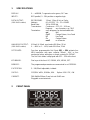
2 FRONT PANEL 6
3 PROGRAMMING with Options 7
4 PROGRAMMING without Options 8
5 TERNINALS (Rear of the instrument) 9
5.1 Upper Terminals (Supply 9-36VDC) 9
5.2 Upper Terminals (Supply 230VAC) 9
5.3 BCD data inputs, RS232 data outputs and Analogue Outputs 10
5.4 BCD parallel Inputs 10
5.5 Excitation – supply for external sensors 11
6 SERIAL DATA PORT 12
6.1 RS 232 Data Format 12
7 BURST TEST and RECOMMENDED CONNECTIONS 13
7.1 Test Conditions 13
7.2 Test Setup 13
7.3 Test Results 13

5
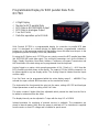
Programmable Display for BCD parallel Data Ports
OC7520
6 Digit Display
Monitor for BCD parallel Data
BCD Data to RS232/RS485 Output
BCD Data to Analogue Output
Four Set Points
Data Bus operation up to 63 Units
Orbit Controls OC7520 is a programmable display for connection to parallel BCD data
ports. It is designed as a remote display for digital meters, programmable controllers,
printers etc. In the measuring mode the 6 digit display shows the data from the port. In the
programming mode the display shows the parameters.
By using the RS Option card, OC7520 can very simply convert the BCD parallel input data
into RS232/RS485 serial data output. The serial port parameters such as the Number of
Digits, Display Resolution, Baud Rate, Address, Continuous or Request Transmission and
the Termination of the data string can be programmed from the keyboard.
Analog Output is an option, which permits generation of 0/4…20mA or 0 …±10V from the
BCD parallel input data shown at the display. The output of 12 bits (4096 increments) can
be free assigned to any two display values. The Analog Output is isolated from the Inputs
and the supply.
Four Set Points can be programmed within the entire display range 0 ... ±999999. They
activate four open collector NPN transistors or four mechanical relays.
The keyboard at the front permits the entry into the menu, setting of RS232 and Analogue
Output parameters as well as setting of the Set Points.
The menu contains 6 digits offset free adjustable which permits the data from the Bus to
be added or subtracted from the offset.
The display intensity can be adjusted in 7 steps with the keys UP or DOWN.
Isolated excitation for supplying of external sensors is available. The parameters are
stored in internal memory also when the power is switched-off. The instrument is supplied
from the mains or from DC voltage and is suitable for panel mount.

6
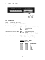
1 SPECIFICATIONS
DISPLAY: 0 ... ± 999999, 7 segments red or green, 14.7 mm.
INPUTS: BCD parallel, 5…24V positive or negative logic.
DATA OUTPUT: RS232/RS485: 1 Start, 1 Stop, 8 bit, no Parity.
(250V RMS Isolation)
Address: 00 = RS232, 01…31 = RS485
Baud Rate: 300 to 19200 bd.
Transmission: Continuous: OFF, 0.1…10.0 sec.
Request: any character, e.g. CRLF
Termination: each telegram can be terminated with:
nul Null
CrLF Carrige Return, Line Feed
LF Line Feed
Cr Carrige Return
nonE no character
ANALOGUE OUTPUT: 0-20mA / 4-20mA, max load ≤ 300 Ohm, 12 bit
(250V RMS Isolation)
0 ... ±10V or 0 ... +10V, load >10 kOhm, 12 bit
SET POINTS: Four free programmable Set Points SP1 ... SP4 activate four
NPN transistors with open collector 100mA - 60V, or four
mechanical relays with open or closed contacts 5A-230VAC.
The Set Point status is displayed with SP1…SP4 at the front.
KEYBOARD: Five keys at the front: UP, DOWN, ACK, MENU, SET.
MEMORY: The programmed parameters are memorized in an EEPROM.
EXCITATION: 5…24V/50mA adjustable, isolated.
SUPPLY: 115/230V ±10%, 50-60Hz, 6VA. Option: 9-36 V DC, 4 W.
CABINET: DIN 48x96x150mm, Panel cut-out 45x93 mm.
Pluggable screw terminals.
2 FRONT PANEL

7
3 PROGRAMMING
(with build-in options RS232 and Analogue output)
Software Version 7520_V5.hex CS: 1120
The menu will be opened with the key MENU. With the same key the submenu will scroll
at the display. The required parameter will be confirmed with ACK. Its value will be set
with UP or DOWN. The flashing digit - Cursor - will be positioned with ACK. The sign and
the decimal point can be set when the flashing display is positioned outside of the display
(no digit flashing). The decimal point will be adjusted with UP, the sign with DOWN.
KEY DISPLAY FUNCTION
MENU OrdEr Display resolution
ACK CCCC.dd Select with UP, DOWN and SET from CCCCCC. to C.ddddd
MENU SP1 Set Point 1
ACK 001000 Select with UP, DOWN and SET
MENU SP2 Set Point 2
ACK 001500 Select with UP, DOWN and SET
MENU SP3 Set Point 3
ACK 002500 Select with UP, DOWN and SET
MENU SP4 Set Point 4
ACK 003000 Select with UP, DOWN and SET
MENU PrESEt Display Offset 6 digits with Decimal Point and Sign
ACK 000000 Select with UP, DOWN and SET
MENU AOUtL Display value for Analogue Output 0/4mA and 0/-10V.
ACK 00000 Select witht UP, DOWN and SET
MENU AOUtH Display value for Analogue Output 20mA and +10V.
ACK 01000 Select with UP, DOWN and SET
MENU BAUD Baud Rate
ACK 19200 Select with UP, DOWN and SET from 300 to 19200 bd.
MENU rS Adr Address of Data Port: 0 activates RS232. One of addresses
ACK ADDR01 01 ... 31 activates RS485
MENU dEIin Termination sign for data output
ACK nonE nonE, Cr, LF, CrLF, nul
MENU IntEr Transmission Interval of the RS Port
ACK nonE nonE, 0.1, 0.2, 0.5, 1.0, 3.0, 5.0, 10.0, Hand
MENU Fn bcd (*) Number of digits for conversion into RS232/485
ACK POS 6 POS 1 … POS 6 positive BCD parallel logik (*)
nEG 1 … nEG 6 negative BCD parallel logik (*)
MENU Fn SIG Activation of SIGN
ACK nEG Selection of the SIGN control
nEG “+” at Pin 25 illuminates the SIGN
POS “0” at Pin 25 illuminates the SIGN
OFF the SIGN is deactivated
MENU OC7520 Measuring Mode

8
(*) Example for setting of Fn bcd:
BCD data input: 123456
POS Display Transmission via RS232
1 100000 1
2 120000 12
3 123000 123
4 123400 1234
5 123450 12345
6 123456 123456
4 PROGRAMMING
(without options)
KEX DISPLAY FUNCTION
MENU SP1 Set Point 1
ACK 001000 Select with UP, DOWN and SET
MENU SP2 Set Point 2
ACK 001500 Select with UP, DOWN and SET
MENU SP3 Set Point 3
ACK 002500 Select with UP, DOWN and SET
MENU SP4 Set Point 4
ACK 003000 Select with UP, DOWN and SET
MENU PrESEt Display Offset free settable
ACK 000000 Select with UP, DOWN and SET
MENU dEC.Pt Decimal Point - Resolution
ACK CCC.ddd Select with UP, DOWN and SET
MENU IFACE BCD parallel (or BCD serial - only upon request)
ACK Par.nEG negative Logic
Par.POS positive Logic
SEr.POS positive Logic
SEr.nEG negative Logic
MENU Adr.bcd Address of the Data Port 0-63
ACK Adr=00 Select with UP, DOWN and SET
MENU OC7520 Measuring Mode

9
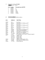
5 TERMINALS (Rear of the instrument)
5.1 Upper Terminals (Supply 24VDC)
Set Points with transistor outputs
5.2 Upper Terminals (Supply 230VAC)
Set Points with four Relays
The relay and the transistor outputs can be combined. The relays can be assembled to
close or to open when activated.

10
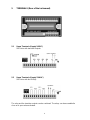
5.3 BCD Data Inputs, RS232/485 Data Outputs and Analogue Outputs
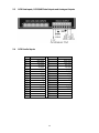
5.4 BCD Parallel Inputs
Pin
INPUT
Pin
INPUT
1 800 000
2 400 000
3 200 000
4 100 000
5 80 000
6 40 000
7 20 000
8 10 000
9 8 000
10 4 000
11 2 000
12 1 000
13 800
14 400
15 200
16 100
17 80
18 40
19 20
20 10
21 8
22 4
23 2
24 1
25 SIGN
26 SIGN
27 GND
28 GND
29
do not use
30
do not use
31
do not use
32
do not use
33
do not use
34
do not use

11
5.5 Excitation - supply for external sensors

12
6 SERIAL DATA PORT
6.1 RS Data Format
Format: 1 Start, 1 Stop, 8 Bit no Parity
Baud Rate: Menu step bAUd: 300 to 19200 bd
Termination: Menu step dElin: nul Null
CrLF Carrige Return Line Feed (0xd und 0xa)
LF Line Feed (0xa)
CR Carrige Return (0xd)
nonE without
Transmitting Interval: Menu step IntEr: none Uninterrupted transmission
0.1 … 10.0 Seconds
Hand Command from PC: any letter from the
PC keyboard any character or ENTER.
Number of digits: Menu step Fn bcd: POS 1 … POS 6 for positive BCD logic
nEG 1 … nEG 6 for negative BCD logic
Example for setting of Fn bcd:
BCD data input: 123456
Fn bcd Display RS Data Format
POS 1 100000 1
POS 2 120000 12
POS 3 123000 123
POS 4 123400 1234
POS 5 123450 12345
POS 6 123456 123456

13
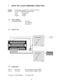
7 BURST TEST and RECOMMENDED CONNECTIONS
Tester: Burst-Surge Generator HILO, Model CE-Tester
E.U.T.: OC7520, SN:990818, Supply 230VA
Mode: BCD parallel
Input: 123456
Display: 123456
7.1 Test Conditions
According to Norms: IEC 801-4
IEC 1000-4-4
EN 50052-1
7.2 Test Set - Up
7.3 Test Results
Zone 1: 2kV Burst Display without change 123456
Zone 2: 2kV Burst Display without change 123456
Technician: Oliver Matthews 18. August 1999
-
 1
1
-
 2
2
-
 3
3
-
 4
4
-
 5
5
-
 6
6
-
 7
7
-
 8
8
-
 9
9
-
 10
10
-
 11
11
-
 12
12
-
 13
13


in anderen Sprachen
- English: Orbit OC 7520 Owner's manual
Andere Dokumente
-
 Magnescale MG30 Bedienungsanleitung
-
Agilent Technologies 6106A Benutzerhandbuch
-
Renkforce Transponder access control Bedienungsanleitung
-
SICK DME4000 Bedienungsanleitung
-
-
SBC 3-phase energy meter AWD3 Mounting Instructions & Users Guide
-
SBC PCD family Bedienungsanleitung
-
-
Eurotherm EPC3000 Bedienungsanleitung
