
6E 5044.b
Energiezähler 3 phasig,
80 A
EC 314P, EC 316P
Funktionsprinzip
Der Energiezähler erfasst die Wirkenergie, die
von einem elektrischen Stromkreis verbraucht
wird.
Darüber hinaus kann der EC 316P erfasste
Energie in zwei verschiedene Tarifbereiche
aufteilen.
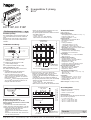
➀
t1/t2 (EC 316P) um die Tarifanzeige
auszuwählen
➁
Blinkende LED-Anzeige bei 2 Wh
➂
Siebenstellige Anzeige
➃
Anzeige der Betriebsart (EC 316P)
Produktbeschreibung:
Tarif 1 und tarif 2 (EC 316P)
Der Zähler teilt den Verbrauch in die Tarif 1
und 2 auf.
1. Standardmäßig zeigt der Zähler den
Verbrauch im laufenden Tarif an.
2. Um den Verbrauch im Tarif 1 oder im
Tarif 2 oder den Gesamtverbrauch Tarif 1
und Tarif 2 zu lesen, drücken Sie mehrere
Male auf die Taste
➀
.
Der Zeiger
➃
auf dem Display gibt jederzeit
den Tarif des angezeigten Verbrauchs an.
Beispiel: Verbrauch im Tarif 1.
PTB zugelassen
Eingang Spannung:
- Versorgungsspannung: 400 V
±15 % (L - L)
- Frequenz: 50 Hz
±2 Hz
- Leistungsaufnahme: < 2 VA
Eingang Strom:
- Direkte Messung: 40 mA bis 80 A
- Einschaltstrom: 40 mA
- Ib = 10 A
- Leistungsaufnahme:
- aufgelegte Leitung ≤ 2,5 VA
- durchführte Leitung ≤ 0,1 VA
- Überlast: 30 x I max. während 10 ms
Bemerkung: Versorgung des Gerätes über
den Spannungseingang.
Elektrische Eigenschaften:
- Schutzart: IP 51 unter Abdeckung
- Schutzklasse: II Schutzisoliert.
Genauigkeit:
IEC 61036 Klasse 1 (1 %) bei 230/400 V
50 Hz und 23°C
Funktionseigenschaften
- Anzeige: Einheit = 0,1 kWh
- Anzeigevermögen: 999 999,9 kWh
➂
- Blinkende LED-Anzeige des
Energieflusses: 2 Wh
➁
- periodisches Speichern der Messungen
und bei Spannungsunterbrechung.
Energie-Impuls-Ausgang:
- Optokoppler: 40 V DC - 200 mA
- Wert eines Impulses: 100 Wh
- Impulsdauer: 100 ms
Tarifeingang 1/Tarifeingang 2:
- Steuerspannung: 230 V
± 15 % (L - N)
- Tarif 1: 0 V AC
- Tarif 2: 230 V AC
Umgebung:
- Betriebstemperatur: -5 °C bis +45 °C
- Lagertemperatur: -20 °C bis +70 °C
- relative Luftfeuchtigkeit: 85 % ohne
Kondensierung.
Abmessungen:
7 PLE (17,5 mm).
Technische Daten:
2. Sie können ebenso Ihre Strom führenden
Leitungen anschließen, indem Sie sie trennen.
- Führen Sie Ihre abisolierten Leitung ein:
- Legen Sie die Abdeckungen der Käfigklemmen
um 180° um.
- Schließen Sie die Strom führenden Kabel an.
- Die Spannung führenden Leiter (starr oder flexibel)
dürfen höchstens einen Querschnitt von:
-6
mm
2
minimum
- 50
mm
2
max. d. h. einen maximalen
Querschnitt von 10,5 mm für den abisolierten Leiter.
NL1L2L3
NL1L2L3
t1 / t2
100 Wh
t1 = 0 V ac
t2 = 230 V ac
-
+
NL1L2L3
NL1L2L3
t1 / t2
100 Wh
t1 = 0 V ac
t2 = 230 V ac
-
+
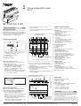
Zugentlastung für
den Leiter
1. zugentlastung
für den Leiter
Zugentlastung
für den Leiter
Es gelten die Allgemeinen Geschäfstbedingungen der Hager
Electro GmbH. bzw. die gesetzliche Regelung.
Garantie
D
2. Kontaktierungsklemmen.
Diese Klemmen müssen
nicht angezogen werden.
t1 t2
kWh
LCD = 500 Imp/ kWh
OUT = 10 Imp/ kWh
1
4
2
3
kWh
t1 t2
Anschlußgrößen
Tarifeingang und Impuls-ausgang:
- flexibel: 1 bis 6 mm
2
- massiv: 1,5 bis 10 mm
2
.
Netzanschluss:
Wir empfehlen Ihnen die folgende minimalen
Querschnitte zu benutzen:
- I < 32 A: 6
mm
2
min.
- 32 A ≤ I < 57 A: 10
mm
2
min.
- 57 A ≤ I < 76 A: 16
mm
2
min.
- 76 A ≤ I < 80 A: 25 mm
2
min.
223316
8
kWh
EC 316P
LCD = 500 Imp/ kWh
OUT = 10 Imp/ kWh
3
X 2
30
/400 V
50 Hz
10 (80)
A
IP 51
cl. 1
20.15
03.19
t1
t2
Elektrischer Anschluss:
Es gibt zwei Möglichkeiten, um die drei
Phasen und den Neutralleiter an das Produkt
anzuschließen.
1. Sie können die Strom führenden Kabel
einfach durch das Gerät durchführen, oder die
Leitungen abisolieren und direkt anschliessen.
- Legen Sie die Abdeckungen der
Käfigklemmen um 180° um.
-Führen Sie die Strom führenden Leitungen
durch.
- Ziehen Sie die Klemmen uten und oben an
um die Leitung zu fixieren.
1. zugentlastung
für den Leiter
- Ziehen Sie die Kontaktierungsklemmen an um
den Spannungspfad anzuschließen.
- Die Spannung führenden Kabel dürfen höchstens
einen Querschnitt von:
- 10 mm
2
minimum
- 25 mm
2
max. d. h. einen äußeren
Querschnitt von maximal 10,5 mm.
6E 5044.b
GB
D
Bedienungsanleitung
D
Nur ein Leiter darf durch jedem Phasen Kanal
geführt werden.
Hager Electro S.A.S. - 132, bld d’Europe - BP3 - 67 215 Obernai cedex - Tél. 03.88.49.50.50 - www.hager.com

6E 5044.b
Three phase kWh meter
80 A
EC 314P, EC 316P
Operating principle
This kilowatt hour meter measures the active
electrical energy used in an electrical installation.
In the case of two tariff levels, the EC 316P will
measure and record separetely the energy
used during tariff 1 or tariff 2 periods.
➀
t1/t2 (EC 316P) to select display of the
consumption on tariff 1 or 2
➁
LED blinking each 2 Wh
➂
7 digits display
➃
t1/t2 tariff indicator
Product presentation:
Warranty
GB
Standards: PTB according to IEC 61036
Voltage input:
- working voltage: 400 V
±15 % (L - L)
- frequency: 50 Hz 2 Hz
- consumption: < 2 VA
Current input :
- direct connection: 40 mA to 80 A
- starting current: 40 mA
- Ib = 10 A
- consumption:
- cut and stripped cables ≤ 2,5 VA
- passing through cables ≤ 0,1 VA
- overload: 30 x I max for 10 ms
Note: the device is self-powered from
the voltage input.
Electrical characteristics:
- IP 51 under cover
- insulation class: II
Accuracy:
IEC 61036 class 1 (1 %) at 230/400 V
50 Hz and with 23°C
Functional characteristics:
- direct reading: unit = 0.1 kWh
- display capacity: 999 999
.
9 kWh
➂
- instant consumption: blinking LED 2 Wh
➁
- savings of measures are made regularly
and in case of power failure.
Impulse transmitter:
- Optocoupler: 40 V DC - 200 mA
- 1 pulse: 100 Wh
- pulse duration: 100 ms
Tariff level input:
- supply: 230V
± 15 % (L - N)
- tariff level 1: 0 Vac
- tariff level 2: 230 Vac
Environment:
- working temperature: -5 °C to +45 °C
- storage temperature: -20 °C to +70 °C
- relative humidity: 85% without condensation
Size: 7 ❚ of 17.5 mm.
Technical specifications
223316
8
kWh
EC 316P
LCD = 500 Imp/ kWh
OUT = 10 Imp/ kWh
3
X 230/400 V
50 Hz
10 (
80)
A
IP 51
cl. 1
20.15
03.19
t1
t2
Electrical connection:
2. It is also possible to connect stripped cables.
- connect your incoming and outgoing cables cut
and stripped.
- position the terminal covers by turning through 180°
- make all necessary connections.
- the cables must have a cross section of
-6 mm
2
minimum
- 50 mm
2
max. this means a diameter of 10,5 mm
maximum (bared).
Tariff 1 and tariff 2 (EC 316P)
The meter will display the consumption in the
corresponding tariff (1or 2).
5. Automatically, the counter will display the
energy used in the tariff in progress.
6. To display the consumption in tariff 1 or
in tariff 2, or the total tariff 1 + tariff 2,
press successively key
➀
.
The indicator
➃
will indicate to which tariff
corresponds the consumption displayed.
ex: consumption on tariff 1.
A warranty period of 24 months is offered on hager products,
from date of manufacture, relating to any material of manufac-
turing defect. If any product is found to be defective it must be
returned via the installer and supplier (wholesaler).
The warranty is withdrawn if :
- after inspection by hager quality control dept the device is
found to have been installed in a manner which is contrary to
IEE wiring regulations and accepted practice within the indus-
try at the time of installation.
- the procedure for the return of goods has not been followed.
Explanation of defect must be included when returning goods.
- the cables must have a cross section of
- 10
mm
2
minimum
- 25
mm
2
max. this means an external diameter of
10,5 mm maximum.
Connection
Tariff input and pulsed output:
- flexible: 1 to 6 mm
2
- rigid: 1,5 to 10 mm
2
.
Power cables :
We recommend to use the following minimum
cross-section (flexible or rigid):
- I < 32 A: 6 mm
2
min.
- 32 A ≤ I < 57 A: 10 mm
2
min.
- 57 A ≤ I < 76 A: 16 mm
2
min.
- 76 A ≤ I < 80 A: 25 mm
2
min.
Hager 04.2004
6E 5044.b
t1 t2
kWh
LCD = 500 Imp/ kWh
OUT = 10 Imp/ kWh
1
4
2
3
kWh
t1 t2
There are 2 solutions to connect the three
phases and the neutral to the kWh meter:
1.
Pass the cables through the kWh meter,
without cutting and stripping them.
- position the terminal covers by turning through
180°
- pass the cables through the kWh meter
- tighten the upper and the bottom terminals
to clamp the cable in position
- tighten at the maximum the piercing screw
to allow the voltage measurement
NL1L2L3
NL1L2L3
t1 / t2
100 Wh
t1 = 0 V ac
t2 = 230 V ac
-
+
NL1L2L3
NL1L2L3
t1 / t2
100 Wh
t1 = 0 V ac
t2 = 230 V ac
-
+
Terminals to tighten to clamp
the bare cable in position
1. terminals to
clamp the cable
in position
Terminals
to tighten to
clamp the bare
cable in position
Not necessary to tighten
these terminals.
1. terminals to clamp
the cable in position
2. piercing screws
D
GB
User instruction
GB
Hager Electro S.A.S. - 132, bld d’Europe - BP3 - 67 215 Obernai cedex - Tél. 03.88.49.50.50 - www.hager.com
Only one cable per phase canal.
-
 1
1
-
 2
2


in anderen Sprachen
- English: Hager EC 314P
Verwandte Artikel
Andere Dokumente
-
Gossen MetraWatt U181, U187, U189 Bedienungsanleitung
-
-
-
Socomec COUNTIS E3x Bedienungsanleitung
-
SBC 3-phase energy meter ALE3 Mounting Instructions & Users Guide
-
ABB i-bus EIB Delta-Meter Installation And Operating Instructions Manual
-