Blade SR Benutzerhandbuch
- Kategorie
- Ferngesteuertes Spielzeug
- Typ
- Benutzerhandbuch

Revised 4/10 www.bladehelis.com 16165.1i
Note: Attempting to fly the helicopter without completely reading the manual may cause injury to yourself and people in
the vicinity, as well as damage to the helicopter.
Hinweis: Der Versuch, den Helikopter zu fliegen, ohne das Handbuch vollständig zu lesen, kann Verletzungen an Ihnen
selbst und Menschen in der Nähe, wie auch Schäden am Helikopter verursachen.
A noter: tenter de faire voler l’hélicoptère sans avoir lu l’intégralité du manuel peut provoquer des blessures (à vous-même
et aux personnes alentour) ainsi que des dégâts à l’hélicoptère.
Nota: Un tentativo di far volare l’elicottero senza aver letto completamente il manuale può avere come risultato una lesione
del manovratore e delle persone circostanti, nonchè danni all’elicottero stesso.
RTF Instruction Manual | RTF Bedienungsanleitung
Manuel d’utilisation RTF | RTF Manuale d’uso

ENDEFRIT
2
EN DE FR IT
3
Table of Contents
Introduction . . . . . . . . . . . . . . . . . . . . . . . . . . . . . . . . . . . . . . . . . . . . . . . . . . . . . . . . . . . . . . . . . . . . . . . . . . . . . . .4
Product Support ............................................................................4
Warning . . . . . . . . . . . . . . . . . . . . . . . . . . . . . . . . . . . . . . . . . . . . . . . . . . . . . . . . . . . . . . . . . . . . . . . . . . . . . . . . . .4
Additional Safety Precautions and Warnings . . . . . . . . . . . . . . . . . . . . . . . . . . . . . . . . . . . . . . . . . . . . . . . . . . . . . . . .4
Specifications ..............................................................................5
Blade SR RTF Contents . . . . . . . . . . . . . . . . . . . . . . . . . . . . . . . . . . . . . . . . . . . . . . . . . . . . . . . . . . . . . . . . . . . . . . .5
Preparing for the First Flight ....................................................................6
Flying Checklist .............................................................................6
Battery Warnings and Guidelines . . . . . . . . . . . . . . . . . . . . . . . . . . . . . . . . . . . . . . . . . . . . . . . . . . . . . . . . . . . . . . . .6
Battery Charging ............................................................................7
Charge Errors and Indications . . . . . . . . . . . . . . . . . . . . . . . . . . . . . . . . . . . . . . . . . . . . . . . . . . . . . . . . . . . . . . . . . .9
Installing the Transmitter Batteries . . . . . . . . . . . . . . . . . . . . . . . . . . . . . . . . . . . . . . . . . . . . . . . . . . . . . . . . . . . . . . .9
Installing the Flight Battery ....................................................................10
Center of Gravity ...........................................................................10
Transmitter Control Identification . . . . . . . . . . . . . . . . . . . . . . . . . . . . . . . . . . . . . . . . . . . . . . . . . . . . . . . . . . . . . . .11
Control Test . . . . . . . . . . . . . . . . . . . . . . . . . . . . . . . . . . . . . . . . . . . . . . . . . . . . . . . . . . . . . . . . . . . . . . . . . . . . . .12
2-in-1 Control Unit Description, Arming and Motor Control Test ..........................................16
Gyro Initialization, Response Test and Adjustment . . . . . . . . . . . . . . . . . . . . . . . . . . . . . . . . . . . . . . . . . . . . . . . . . . .17
Initialization and Response Test . . . . . . . . . . . . . . . . . . . . . . . . . . . . . . . . . . . . . . . . . . . . . . . . . . . . . . . . . . . . . . . .18
Gain Adjustments . . . . . . . . . . . . . . . . . . . . . . . . . . . . . . . . . . . . . . . . . . . . . . . . . . . . . . . . . . . . . . . . . . . . . . . . . .19
Trim Adjustments . . . . . . . . . . . . . . . . . . . . . . . . . . . . . . . . . . . . . . . . . . . . . . . . . . . . . . . . . . . . . . . . . . . . . . . . . .19
Servo Mode Setting. . . . . . . . . . . . . . . . . . . . . . . . . . . . . . . . . . . . . . . . . . . . . . . . . . . . . . . . . . . . . . . . . . . . . . . . .20
Installing the Optional Training Gear . . . . . . . . . . . . . . . . . . . . . . . . . . . . . . . . . . . . . . . . . . . . . . . . . . . . . . . . . . . . .20
Understanding the Primary Flight Controls .........................................................22
Dual Rates ...............................................................................25
Normal and Stunt Flight Modes ................................................................26
Throttle Hold . . . . . . . . . . . . . . . . . . . . . . . . . . . . . . . . . . . . . . . . . . . . . . . . . . . . . . . . . . . . . . . . . . . . . . . . . . . . .28
Before the First Flight .......................................................................29
Choosing a Flying Area . . . . . . . . . . . . . . . . . . . . . . . . . . . . . . . . . . . . . . . . . . . . . . . . . . . . . . . . . . . . . . . . . . . . . .29
Flying the Blade SR .........................................................................29
Tail Rotor Proportional Mix Trimmer Pot Adjustment . . . . . . . . . . . . . . . . . . . . . . . . . . . . . . . . . . . . . . . . . . . . . . . . .31
Main Rotor Blade Tracking Adjustment . . . . . . . . . . . . . . . . . . . . . . . . . . . . . . . . . . . . . . . . . . . . . . . . . . . . . . . . . . .32
Flybar Paddle Tracking Adjustment ..............................................................33
Flybar Weights, Head Dampening Shims and Fine-Tuning Cyclic Response ..................................34
Channel 5 Knob . . . . . . . . . . . . . . . . . . . . . . . . . . . . . . . . . . . . . . . . . . . . . . . . . . . . . . . . . . . . . . . . . . . . . . . . . . .35
Transmitter, Receiver Binding and Fail-Safe ........................................................36
Transmitter and Receiver Range Testing . . . . . . . . . . . . . . . . . . . . . . . . . . . . . . . . . . . . . . . . . . . . . . . . . . . . . . . . . .37
2010 Official Academy of Model Aeronautics Safety Code . . . . . . . . . . . . . . . . . . . . . . . . . . . . . . . . . . . . . . . . . . . . .37
Replacement Parts List . . . . . . . . . . . . . . . . . . . . . . . . . . . . . . . . . . . . . . . . . . . . . . . . . . . . . . . . . . . . . . . . . . . . . .39
Optional Parts List ..........................................................................39
Exploded View Parts Listings ..................................................................40
Exploded View . . . . . . . . . . . . . . . . . . . . . . . . . . . . . . . . . . . . . . . . . . . . . . . . . . . . . . . . . . . . . . . . . . . . . . . . . . . .41
Warranty and Repair Policy . . . . . . . . . . . . . . . . . . . . . . . . . . . . . . . . . . . . . . . . . . . . . . . . . . . . . . . . . . . . . . . . . . .42
Compliance Information for the European Union .....................................................44
NOTICE
All instructions, warranties and other collateral documents are subject to change at the sole discretion of Horizon
Hobby, Inc. For up-to-date product literature, visit http://www.horizonhobby.com and click on the support tab for
this product.
Meaning of Special Language
The following terms are used throughout the product literature to indicate various levels of potential harm when
operating this charger:
NOTICE: Procedures, which if not properly followed, create a possibility of physical property damage AND a small
or null possibility of injury.
CAUTION: Procedures, which if not properly followed, create the probability of physical property damage AND a
possibility of serious injury.
WARNING: Procedures, which if not properly followed, create the likely probability of physical property damage
AND may lead to a dangerous condition or cause death or serious injury to the user, OR procedures, which if not
followed, create the high probability of superficial injury.
WARNING: Read the ENTIRE instruction manual to become familiar with the features of the
product before operating. Failure to operate the product correctly can result in damage to the
product, personal property and cause serious injury.
This is a sophisticated hobby product and NOT a toy. It must be operated with caution and common sense and
requires some basic mechanical ability. Failure to operate this Product in a safe and responsible manner could
result in injury or damage to the product or other property. This product is not intended for use by children without
direct adult supervision. Do not attempt disassemble, use with incompatible components or augment product in
any way without the approval of Horizon Hobby, Inc. This manual contains instructions for safety, operation and
maintenance. It is essential to read and follow all the instructions and warnings in the manual, prior to assembly,
setup or use, in order to operate correctly and avoid damage or serious injury.

ENDEFRIT
4
EN DE FR IT
5
Introduction
Your Blade
®
SR is the absolute best way to transition from flying a coaxial heli to a single-rotor CCPM machine with
confidence and, most importantly, success. It comes out of the box programmed to provide softer climb, pitch and roll
response around the center of stick movement. This, combined with the tough, two-piece main frame and lower head speed,
makes the Blade SR more forgiving and easier to master than most conventional CP helis. Plus, it’s big enough to fly
outdoors even if there’s a little wind.
But before you take that first flight, read through this manual thoroughly. It includes vital information on safely charging
the battery, proper pre-flight control checks and adjustments, and many other tips that will help make your first flight a
successful one.
Product Support
For assistance in charging, setting up, binding or operating your Blade SR, please see page 43 to contact the appropriate
Horizon Product Support office.
Warning
An RC helicopter is not a toy! If misused, it can cause serious bodily harm and damage to property. Fly only in open areas,
preferably at AMA (Academy of Model Aeronautics) approved flying sites, following all instructions.
Keep items that can get entangled in the rotor blades away from the main and tail blades, including loose clothing, pencils
and screwdrivers. Especially keep your hands away from the rotor blades.
Additional Safety Precautions and Warnings
As the user of this product, you are solely responsible for operating it in a manner that does not endanger yourself and
others or result in damage to the product or the property of others.
This model is controlled by a radio signal that is subject to interference from many sources outside your control. This
interference can cause momentary loss of control so it is advisable to always keep a safe distance in all directions around
your model, as this margin will help to avoid collisions or injury.
Never operate your model with low transmitter batteries.•
Always operate your model in an open area away from cars, traffic or people.•
Avoid operating your model in the street where injury or damage can occur.•
Never operate the model out into the street or populated areas for any reason.•
Carefully follow the directions and warnings for this and any optional support equipment (chargers, rechargeable battery •
packs, etc.).
Keep all chemicals, small parts and anything electrical out of the reach of children.•
Moisture causes damage to electronics. Avoid water exposure to all equipment not specifically designed and protected •
for this purpose.
Never lick or place any portion of your model in your mouth as it could cause serious injury or even death.•
Specifications
Length ....................... 19.10 in (485mm)
Height ....................... 6.90 in (176mm)
Main Rotor Diameter ............. 21.80 in (552mm)
Tail Rotor Diameter .............. 3.20 in (82mm)
Weight with Battery. . . . . . . . . . . . . . 120 oz (340 g)
Main Motor . . . . . . . . . . . . . . . . . . . Brushless 3900Kv (installed)
Tail Motor . . . . . . . . . . . . . . . . . . . . Direct-Drive N60 (installed)
Battery . . . . . . . . . . . . . . . . . . . . . . 3S 11.1V 1000mAh Li-Po (included)
Charger ...................... 3-Cell 11.1V Li-Po
Power Supply .................. AC to 12V DC, 1.5A (included)
Transmitter . . . . . . . . . . . . . . . . . . . HP6DSM 2.4GHz DSM 6-channel (included)*
Receiver . . . . . . . . . . . . . . . . . . . . . Spektrum AR6110e 2.4GHz DSM Microlite (installed)
On-Board Electronics . . . . . . . . . . . . 2-in-1 Mixer/ESCs (installed)
Servos . . . . . . . . . . . . . . . . . . . . . . DS75 Digital Sub-Micro (3 installed)
Gyro . . . . . . . . . . . . . . . . . . . . . . . . G110 Micro Heading Lock (installed)
* CCPM Helicopter programming is specific to Blade SR. Please do not attempt to use transmitter with any other
CCPM helicopter
Blade SR RTF Contents
Item Description
Not Available Separately .......... Blade SR RTF Airframe
EFLH1057 .................... HP6DSM 6-Channel Transmitter, 2.4GHz DSM2: BSR
EFLB0997 .................... 1000mAh 3S 11.1V 15C Li-Po, 20AWG JST/Balance
EFLC3105 .................... 3S 11.1V Li-Po Balancing Charger, 0.8A
EFLC4000 .................... AC to 12V DC, 1.5- Amp Power Supply
EFLH1519 .................... Micro Helicopter Main Blade Holder: BSR
EFLH1129 .................... Mounting Accessories & Wrench
EFLH1528 .................... Hook and Loop Material
EFLH1444 .................... Hook and Loop Strap
FUG4. . . . . . . . . . . . . . . . . . . . . . . . 4 AA Batteries
No additional equipment is required to complete your Blade SR.

ENDEFRIT
6
EN DE FR IT
7
Preparing for the First Flight
Please note this checklist is not intended to be a replacement for the content of this instruction manual. Although it can be
used as a quick start guide, we strongly suggest reading through this manual completely before proceeding.
Remove and inspect contents•
Begin charging the flight battery (see charging procedures on following pages)•
Install the 4 included AA batteries in the transmitter•
Install the flight battery in the helicopter (once it has been fully charged)•
Check the Center of Gravity of the helicopter (see page 12)•
Test the controls (see page 14)•
Install the optional Training Gear Set (EFLH1527; strongly recommended if this is your first collective-pitch equipped •
helicopter model)
Familiarize yourself with the controls•
Find a suitable area for flying•
Flying Checklist
Please note this checklist is not intended to be a replacement for the content of this instruction manual. Although it can be
used as a quick start guide, we strongly suggest reading through this manual completely before proceeding.
Always turn the transmitter on first ❏
Plug the flight battery into the 2-in-1 control unit ❏
Allow the 2-in-1 control unit and gyro to arm and initialize properly ❏
Fly the model ❏
Land the model ❏
Unplug the flight battery from the 2-in-1 control unit ❏
Always turn the transmitter off last ❏
Battery Warnings and Guidelines
The 3S 11.1V 1000mAh Lithium Polymer Battery Pack (EFLB0997) included with your Blade SR features
Charge Protection Circuitry and Balance Charging via the included 3S 11.1V Lithium Polymer Balancing
Charger (EFLC3105). However, to help ensure a safe charge every time, you MUST read the following safety
instructions and warnings before handling, charging or using the Li-Po battery pack.
CAUTION: Lithium Polymer batteries are significantly more volatile than the alkaline, Ni-Cd or Ni-MH
batteries used in RC applications. All instructions and warnings must be followed exactly.
Mishandling of Li-Po batteries can result in fire property damage and injury.
By handling, charging or using the included Li-Po battery you assume all risks associated with lithium batteries.
If you do not agree with these conditions, return your complete Blade SR model in new, unused condition to the
place of purchase immediately.
You must charge the included 3S 11.1V 1000mAh Li-Po battery pack in a safe area away from flammable materials.•
Do not charge the battery when installed in the helicopter.•
Never charge the battery unattended. When charging the battery you should monitor the charging process and react to •
potential problems that may occur.
After flight, the battery must be cooled to ambient temperature before charging.•
•You MUST use the included 3S 11.1V Li-Po Balancing Charger ONLY. Failure to do so may result in a fire causing
personal injury and/or property damage. DO NOT use an Ni-Cd or Ni-MH charger.
If at any time during the charge or discharge process the battery begins to balloon or swell, discontinue charging or •
discharging immediately. Quickly and safely disconnect the battery, then place it in a safe, open area away from
flammable materials to observe it for at least 15 minutes. Continuing to charge or discharge a battery that has begun to
balloon or swell can result in a fire. A battery that has ballooned or swollen even a small amount must be removed from
service completely.
In the event of a crash, you must quickly and safely disconnect and remove the battery from the model, then place it in a •
safe, open area away from flammable materials to observe it for at least 15 minutes.
Store the battery at room temperature at approximately ½ charge (3.8V per cell; 11.4V for a 3S battery pack) for best •
results.
When transporting or temporarily storing the battery, the temperature range should be from 40–120 degrees Fahrenheit. •
Do not store the battery or model in a car or direct sunlight whenever possible. If stored in a hot car, the battery can be
damaged or even catch fire.
Do not over-discharge the battery. Discharging the battery too low can cause damage to the pack resulting in reduced •
performance and duration.
Li-Po cells should not be discharged to below 3V each under load. In the case of the 3S Li-Po packs used for the Blade •
SR, you will not want to allow the battery to fall to below 9V during flight.
Over-discharge of the Li-Po battery pack can result in shortened flight times, loss of power output or failure of the pack •
entirely.
Battery Charging
It is important that you only charge the included 3S 11.1V 1000mAh Li-Po Battery Pack (EFLB0997) with the included 3S
11.1V Li-Po Balancing Charger (EFLC3105). Your battery pack is equipped with special Charge Protection Circuitry and a
Balance Charge Lead with connector that is only compatible with this charger. Attempting to charge the pack using another
Li-Po charger or non Li-Po compatible charger could result in serious damage. Please familiarize yourself thoroughly with the
Battery Warnings and Guidelines section before continuing.
The included 3S 11.1V Li-Po Balancing Charger will charge a near fully discharged (not over-discharged) 3S 11.1V 1000mAh
Li-Po Battery Pack in approximately 1.2–1.5 hours. In some cases the charge time may be shorter depending on the actual
amount of capacity left in the pack after a flight. NEVER charge the battery unattended.
Note: The Li-Po battery pack included with your Blade SR will arrive partially charged. For this reason the initial charge
may only take approximately 30–50 minutes.
The charger requires up to 1.5 amps of 11.5–15-volt DC input power that can be supplied by the included AC to 12V DC,
1.5-amp Power Supply (EFLC4000) for convenient charging anywhere an AC outlet is available. NEVER attempt to power
the charger from an AC outlet without the use of a proper AC to DC adapter/power supply.
Note: When using the AC to DC adapter/power supply, the charger is protected to prevent damage if the alligator clips
touch. However, please take care to ensure that the alligator clips do not cause shorting of the battery, adapter/
power supply, etc. by keeping them clear.

ENDEFRIT
8
EN DE FR IT
9
Input power for the charger can also be supplied from a small 12-volt gel cell or car battery.
The charger is equipped with two LED indicators marked RED and GREEN on the label. These LEDs indicate the following
(also found on the label of the charger):
Red Flashing LED Only:• Input power with no battery connected
Red and Green Solid LED:• Battery connected and charging
Red Solid LED Only:• Charge complete
Red and Green Flashing LED:• Charge error
Once you have connected the charger to a power source (use care to ensuring proper polarity when connecting the charger
to the power source), its red LED flashes to indicate the charger has power and is ready to begin charging. Connect the Li-
Po battery pack to the charger using the specially marked Balance Charge Lead exiting the battery pack and the connector
labeled with 11.1V on the charger. The connector is keyed to prevent reverse polarity connection.
When the battery is properly connected and charging normally, the red and green LED indicators will glow solid. Once the
battery has been fully charged, the green LED will go out, leaving just the red LED glowing solid. The battery can now be
removed from the charger and installed into the Blade SR for flight.
Charge Errors and Indications
In the event that both the red and green LEDs flash, a charge error has occurred. Some examples of charge errors and their
indications include:
Alternating flashing of the red and green LEDs indicates that the charge process has been interrupted. If input power to •
the charger has been interrupted due to disconnection from the power source or a drop in voltage/current output from
the power source, unplug the battery from the charger. Next, check to make sure that the input power plug from the
AC to 12V DC adapter/power supply is connected or that the alligator clips are firmly and properly attached to the
power source. Also be sure that the power source is providing the proper amount of voltage and current required to the
charger.
After confirming the connections and that the power source is delivering the necessary voltage and current, restart the
charging process by connecting the battery pack. Continue to monitor the charging process to ensure that no further
charge errors occur.
Simultaneous flashing of the red and green LEDs indicate that the voltage of the Li-Po battery pack is too low to allow the •
charging process to begin. In this case the battery may have been over-discharged due to flying the model too long, or a
single cell or even all cells in the battery pack may be damaged. (For more information on preventing over-discharge of
the Li-Po battery pack, see the Battery Warnings and Guidelines section.)
If after several charging attempts you continue to see this charge error indication, you should remove the battery pack
from service and replace it with a new one.
Installing the Transmitter Batteries
Install the 4 included AA batteries in the transmitter. Check the power level of the batteries and operation of the
transmitter by switching the power switch on (upward). The LCD screen at the top of the transmitter will indicate the power
level of the batteries. If at any time the voltage indicated on the LCD screen falls to 4.5V or less, an alarm will sound, and it
will be necessary to replace the batteries with new ones.
Note: Because the HP6DSM transmitter included with the Blade SR is equipped with Spektrum 2.4GHz DSM2
technology, it does not require the same input voltage or current consumption as a typical 72MHz transmitter for
proper operation and optimum performance.

ENDEFRIT
10
EN DE FR IT
11
Installing the Flight Battery
Use the included hook and loop material for mounting the Li-Po battery pack. We suggest installing the loop (fuzzy) material
on the battery pack and the hook material on the battery support. You should also use the included hook and loop battery
strap for the most secure attachment of the battery to the helicopter.
Center of Gravity
Once you have properly installed and secured the battery, check the helicopter’s center of gravity. With the canopy installed,
lift the helicopter by the flybar with the flybar positioned perpendicular to the tail boom. Move the battery forward or
rearward as required to achieve a slightly nose down or perfectly level helicopter position. You should always check the CG
of your Blade SR before flying, especially if you are switching between different sizes and types of battery packs.
Support by Flybar
Level or Slightly
Downward Angle
Transmitter Control Identification
Note: Before each flight ALWAYS turn the transmitter on before connecting the flight battery to the 2-in-1 unit. After each
flight, you should always disconnect the flight battery from the 2-in-1 unit before powering the transmitter off.
Throttle Trim
Aileron Trim
Elevator Trim
Rudder Trim
Elevator Trim
Aileron Trim
Throttle Trim
Rudder Trim
Rudder/Throttle
Functions
Rudder/Elevator
Functions
Aileron/Elevator
Functions
Aileron/Throttle
Functions
Mode 1
Mode 2

ENDEFRIT
12
EN DE FR IT
13
Control Test
Although each Blade SR model is test flown at the factory, you should test the controls prior to the first flight to ensure none
of the servos, linkages or parts were damaged during shipping and handling. Before proceeding, unplug the three bullet
connectors between the main motor and ESC and tail motor from the 2-in-1 control unit. It is not safe to perform the control
test with the main or tail motor plugs connected to the 2-in-1 control unit after power up.
Turn the transmitter on first and lower the throttle stick and trim completely. Then, plug the battery into the battery lead of
the 2-in-1 unit.
M2
M1
Position the helicopter to view it from the left or right side. Move the left-hand stick up and down to check the collective pitch
control. When the stick is pushed up, the swashplate should lower, increasing the pitch of the main blades.
M2
M1
With the stick pulled back down, the swashplate should raise, decreasing the pitch of the main blades.
M2
M1
Again viewing the helicopter from the left or right side, move the right-hand stick forward and aft to check elevator pitch
control. When the stick is pushed forward, the swashplate should also tilt forward.
M2
M1

ENDEFRIT
14
EN DE FR IT
15
With the stick pulled back, the swashplate will tilt toward the rear.
M2
M1
While viewing the helicopter from the rear (tail boom toward you), move the right-hand stick left and right to check aileron roll
control. When the stick is pushed to the left, the swashplate should also tilt left.
M2
M1
With the stick pushed right, the swashplate will tilt to the right.
M2
M1
If at any time during the test the controls do not respond properly, double-check the positions of the dip switches located
under the door on the bottom left front of the transmitter. These dip switches set the transmitter programming for functions
such as servo reversing, model type and various forms of mixing. Each switch should be set in the position as shown for
proper control of the Blade SR.
For added reference, the following are the functions and available settings for each dip switch (default settings for the Blade
SR are underlined):
Dip Switch 1*: Up – Channel 1/Throttle channel reversed Down – Channel 1/Throttle channel normal
* For safety, channel 1/throttle channel reversing can only be changed when the transmitter is powered off. All other dip
switch positions/functions can be changed while the transmitter is powered on.
Dip Switch 2: Up – Channel 2/Aileron channel reversed Down – Channel 2/Aileron channel normal
Dip Switch 3: Up – Channel 3/Elevator channel reversed Down – Channel 3/Elevator channel normal
Dip Switch 4: Up – Channel 4/Rudder channel reversed Down – Channel 4/Rudder channel normal
Dip Switch 5: Up – Channel 5/Gear channel reversed Down – Channel 5/Gear channel normal
Dip Switch 6: Up – Channel 6/Pitch channel reversed Down – Channel 6/Pitch channel normal
Dip Switch 7: Up – Helicopter Mode (Channel 6 becomes pitch channel) Down – Airplane Mode (Channel 6 becomes an
extra aileron channel)
Dip Switch 8*: Up – 120-degree Cyclic Collective Pitch Mixing (CCPM) Down – Standard mixing
*Only functions when in helicopter mode.
Dip Switch 9*: Up – Rudder/Elevator mixing Down – No mixing
*Only functions when in airplane mode, and no function if switch 10 is in the up position.
Dip Switch 10*: Up – Elevator/Aileron mixing Down – No mixing
*Only functions when in airplane mode, and no function if switch 9 is in the up position.
If the controls still do not respond properly after ensuring the dip switch positions are correct, you should also check the
servo connections to the receiver. The servos should be connected to the corresponding channel on the receiver as follows
(when viewing the helicopter from behind):
AILE (Aileron) Channel – Left-hand rear aileron servo
ELEV (Elevator) Channel – Forward elevator servo
AUX1 (Pitch) Channel – Right-hand rear pitch servo
Once you’ve confirmed the proper dip switch positions and servo connections, all controls should be functioning properly.
However, if you continue to encounter any problems with your Blade SR responding properly to the transmitter, do not fly.
If you’ve confirmed proper control operation of your Blade SR, unplug the flight battery and reconnect the main and tail
motors to the 2-in-1 unit, taking care to connect them to the proper leads using the markings on the label for reference.

ENDEFRIT
16
EN DE FR IT
17
2-in-1 Control Unit Description, Arming and Motor Control Test
Your Blade SR is equipped with a lightweight combination of main motor and tail motor electronic speed controls and main
motor and tail motor proportional mixer. The 2-in-1 has an 8-amp brushless ESC for the main motor that is specifically
designed for use in helicopter models. The ESC is not programmable for use in other applications; however, it is equipped
with features and functions that optimize its performance for the Blade SR. These features and functions include:
“Soft” Low Voltage Cutoff •
The ESC features a “soft” low voltage cutoff (LVC) that occurs when the battery reaches approximately 9V under load.
This helps prevent “deep” over-discharge of the Li-Po battery during use. Please see the Battery Warnings and Guidelines
section for more information regarding the soft LVC feature and how to prevent over-discharge of the Li-Po battery.
Soft (Slow) Start •
The soft (slow) start function of the ESC is intended to help prevent potential damage of the Gear train, motor and ESC
by slowly increasing power to the motor (particularly when the rotor blades are not already spinning). The first time you
power up the ESC after it has been powered on and armed, it will take approximately 15 seconds for the ESC/motor
to reach the power level you initially set with the throttle stick/curve. This means you will need to wait approximately 15
seconds before attempting any aggressive maneuvering to allow the power system to reach the set level of power first.
Any time (after the initial soft startup occurs) the ESC/motor have been powered down completely (to 0% power) for
approximately 15 seconds or more, the soft start will occur again. This is particularly helpful if you land the helicopter
to make an adjustment as you will not need to rearm the ESC in order to perform a soft startup. It is simply best to wait
approximately 15 seconds before powering up the ESC/motor again for flight.
Fast Start •
The fast start function of the ESC allows any level of power to be applied almost immediately after ESC/motor have
been powered down completely (to 0% power) for any amount of time less than approximately 15 seconds. This is
particularly helpful if you accidentally bump the Throttle Hold switch or when aborting an auto-rotation attempt as it will
allow the ESC/motor to reach any power level you have set with the throttle stick/curve almost immediately when the
Throttle Hold switch is set back to the OFF (0) position.
The following checklist contains the steps you must follow to ensure proper arming and operation of the 2-in-1 unit, as
well as proper motor response.
Before each flight ALWAYS turn the transmitter on before connecting the flight battery to the 2-in-1 unit. Never connect •
the flight battery to the 2-in-1 unit before powering the transmitter on first. After each flight, always disconnect the flight
battery from the 2-in-1 unit before powering the transmitter off.
Note: The antennas exiting the Spektrum AR6100e receiver should extend outward (to the left and right of the helicop-
ter) as much as possible for the best overall performance. Be sure to double-check the position and orientation of
both antennas before each flying session, especially if the helicopter was taken out of a box or carrying case.
Both the throttle (left-hand) stick and throttle trim MUST be in their lowest possible position in order for the 2-in-1 unit to •
arm. The flight mode (F MODE) switch must also be in the normal (0) flight mode position with the switch toggled toward
the back of the transmitter for the unit to arm.
If this is the first test flight, or a test flight following repairs, you will also want to center the rudder, aileron and elevator
trims (reference Transmitter Control Identification on page 13).
Turn the transmitter on and ensure it has adequate battery power, as displayed by the LCD screen at the top of the •
transmitter. It is now safe to connect the flight battery to the 2-in-1 unit.
Note: Do not move or sway the helicopter until the red LED on the gyro illuminates solidly. This will be covered in more
detail in the next section.
With battery power applied, and once the orange LED of the Spektrum AR6100e receiver glows solidly to indicate a •
positive link to the transmitter, you will hear two “beeps” from the 2-in-1, indicating it has armed properly. The final step
of the initialization is for the red LED on the gyro to illuminate solidly.
When you have heard two “beeps”, the unit is armed and ready for flight. Use caution as both the main and tail rotors •
will now spin with throttle stick input. For safety, once the unit is armed, the main and tail motors will not spin with the
throttle stick and trim in their lowest positions. However, we also suggest setting the throttle hold (TH HOLD) switch in
the on (1) position, toward the front of the transmitter, once the 2-in-1 unit has armed. This will keep the motors and
rotor blades from spinning while you handle the helicopter and transmitter.
If you have not set the throttle hold switch to the on position, or after you set the switch to the off (0) position toward the
back of the transmitter, DO NOT advance the throttle stick until you are clear of the rotor blades and ready to fly.
Note: If you do not hear two beeps or if you hear a constant series of beeps after battery power is applied, the
2-in-1 unit has not armed properly. A constant series of beeps indicates the throttle is set too high for initialization.
Please review the following.
Confirm that the throttle stick is in the lowest possible position and that the throttle trim is set in approximately the ❏
middle position.
Confirm that the Flight Mode (F MODE) switch is set to the “Normal” (0) position. ❏
Confirm you have a positive RF link between the transmitter and receiver. First, check to be sure the transmitter has ❏
been powered on and has an adequate level of battery power. If the transmitter is powered on and functioning properly,
disconnect the flight battery from the 2-in-1, then reconnect it. Watch for the orange LED of the receiver to begin
glowing solidly, and once it does, the 2-in-1 unit should arm normally.
Once you have placed the helicopter in a safe area, free of obstructions, and are clear of the rotor blades, you can safely •
begin to power up the model to check for proper operation of the motors.
Advance the throttle stick upward slowly, just until both the main and tail rotor blades begin to spin. DO NOT attempt to •
fly the helicopter at this time. Note the direction the main and tail rotor blades spin. The main rotor blades should spin
clockwise when viewed from the top, with the tail rotor blade spinning clockwise when viewed from the right-hand side of
the helicopter. If the main rotor blades are operating in the wrong direction, simply reverse the position of any two motor
wire lead connections to the 2-in-1 unit.
With the tail motor/rotor spinning at a low rpm, check that the tail rotor is responding properly to transmitter inputs. •
When inputting a slight amount of right rudder, the tail rotor rpm’s should increase, pushing the nose of the helicopter to
the right. If you are on carpet, grass, or an otherwise uneven surface, be very careful not to allow the helicopter to catch
the vertical fin when testing the tail rotor control on the ground (or during liftoff when beginning a flight).
After confirming that both rotor blades are rotating in the correct directions, and the tail rotor is responding properly to
rudder inputs, your Blade SR is ready for flight. However, please be sure to review the following sections of the manual
BEFORE proceeding with the first flight.
Gyro Initialization, Response Test and Adjustment
Your Blade SR model is equipped with an E-flite G110 Micro Heading Lock Gyro. This gyro offers an excellent blend of size,
weight, features and performance.

ENDEFRIT
18
EN DE FR IT
19
Initialization and Response Test
The following checklist includes the steps to properly initialize and operate the gyro.
After connecting the flight battery to the 2-in-1 unit, do not move or sway the helicopter. Allow it to remain motionless •
until the red LED on the gyro illuminates solidly, indicating that the gyro has initialized properly and is ready for use.
Note: It is extremely important that you do not move or sway the helicopter after powering it on and before the gyro
initializes. The gyro must be allowed adequate time to record the neutral position in order to initialize for proper
operation. If you ever accidentally move the helicopter after powering it on and before the gyro initializes, power
the helicopter off (by disconnecting the flight battery from the 2-in-1 unit) and repeat the correct process.
Once the gyro initializes properly, and before making your first flight, confirm that the gyro is responding properly to the •
movements of the helicopter and providing proper inputs to the tail rotor in order to counteract any unwanted changes in
yaw.
For added safety during the test, disconnect the main motor from the 2-in-1 control unit.
Then secure the helicopter and ensure that all objects are free and clear of the tail rotor blades Reconfirming that the •
main motor has been disconnected from the 2-in-1 control unit, advance the throttle/collective stick on the transmitter
to approximately 1/4–1/2 travel. Use caution, as the tail motor may begin to spin the tail rotor blade.
Now it is necessary to confirm that the tail motor/rotor responds properly to inputs from the gyro. While holding the •
helicopter securely and ensuring that all objects are free and clear from the tail motor, quickly twist the nose of the
helicopter to the left. If the tail motor/rotor is responding properly to inputs from the gyro, the rpm’s will increase to
counteract the nose twisting to the left, in order to bring the nose back to the right. When quickly twisting the nose of the
helicopter to right, the rpm’s should decrease or stop entirely. If the tail motor/rotor is not responding properly, use the
reverse switch located on the gyro to reverse the direction of response.
After confirming that the tail motor/rotor responds properly to inputs from the gyro, disconnect the •
battery from the 2-in-1 control unit. Then, power down the transmitter and reconnect the main motor to
the 2-in-1 unit.
Now that you’ve confirmed the gyro provides proper inputs to the tail motor/rotor, review the following sections of the
manual BEFORE proceeding with the first flight.
Gain Adjustments
The G110 offers optional-use remote mode selection and gain adjustment features. These features allow the gyro mode
(Standard Rate or Heading Lock) and gain values to be set remotely in the transmitter. However, for simplified use, while
maintaining maximum performance in the Blade SR, these features will not be utilized (they are usually best utilized when
using a programmable computer transmitter).
Because you will not be utilizing the remote mode selection and gain adjustment features of the gyro, the gyro’s •
yellow-colored auxiliary (AUX) lead and connector will not be plugged into the receiver. This is not a problem as the gyro
will always be in the heading lock mode and the gain value can be set using the gain value adjustment pot located on the
gyro itself.
After making the initial test flight, you may find that it is necessary to adjust the gyro gain setting value prior to •
subsequent test flights in order to achieve the best possible performance. The goal, when using a heading lock type
gyro, is to find the highest gain setting value at which the tail/nose of the helicopter does not twitch quickly (oscillate)
from side to side in all areas of flight (including fast forward flight and descents). In the case of the G110 in the Blade
SR, we find that it is typical to have the gain setting adjustment pot set as shown below, which is only a few degrees off
of full counterclockwise.
Optimum Range
Small, air swooshing noises along with a small amount of movement side to side is normal for a direct-drive tail system, •
like that found on the Blade SR. Don’t confuse this for a gain setting that is too high.
Note: If the tail spins in one direction or the other as you are trying to lift off, please check the gyro gain. It may be
adjusted too high or too low.
Trim Adjustments
During flight, it may be necessary to make some small adjustments to the rudder trim in order to prevent the nose/tail of
the model from “drifting” to the left or right when the rudder stick is in the neutral position. Typically, only a small amount of
adjustment may be necessary.
Note: It is always best to avoid sudden temperature and environmental condition changes when using a gyro. For
example, it is best to not fly a model on a very hot (or cold) day immediately after removing it from an
air-conditioned (or heated) vehicle. It is also best to keep the gyro out of direct sunlight and away from any
heat-generating sources on the model.
To help the gyro better acclimate to temperature and environmental conditions at the flying field, it is best to let your Blade
SR stand in the environment for approximately 10–15 minutes before flying, allowing the temperature of the gyro sensor to
stabilize. If you do not allow the temperature to stabilize, you may experience radical trim changes that require significant
adjustments of the rudder trim during flight.

ENDEFRIT
20
EN DE FR IT
21
Servo Mode Setting
The G110 is equipped with a switch and software that allows its performance to be optimized for use with most analog and
some digital servos. The servo mode selection switch is found on the side of the gyro.
However, because the Blade SR uses an ESC and motor to control the tail, you must be certain that the servo mode
selection switch on the gyro is set to standard servo mode to ensure proper response and performance of the gyro. If it is
set to digital servo mode, the electronic speed control and tail motor will not respond properly to inputs from the gyro or
transmitter. This could even cause failure of the motor, ESC or both.
Installing the Optional Training Gear
If the Blade SR is your first single-rotor and/or collective-pitch equipped helicopter model, we suggest that you install the
optional Training Gear Set (EFLH1527) before making your first flight. The training gear helps to further increase the stability
of the model while also providing added support and cushioning to prevent tip-overs and damage to the model from abrupt
landings.
Installing the training gear takes only a few minutes following these steps.
The training gear set includes four plastic balls, four ball grommets, four training gear rods, four rod end caps, four •
training gear rod to landing skid attachments and one training gear rod mounting base.
Locate the four training gear rod to landing skid attachments. Snap the attachments to the landing skids as •
shown below.
After installing all four attachments, locate the four training gear rods and rod mounting base. Note that the rod •
mounting base has a “coned” shape to it. The “pointed” side of the base will face upward toward the bottom of the
helicopter when properly installed. The base also has two different angles where the gear rods attach. It is important to
orient the base so that the large angle is facing forward and backward.
Carefully pass each of the rods through the holes in the attachments on the landing skids and into the channels on the •
base. The rods will pass through the front holes of the forward attachments, and the back holes of the rear attachments.
You may find it necessary to apply some light pressure to the rods, base and landing skids when installing all four rods in
the base. This is typical; however, take care to not damage any of the parts.
Once all four rods are installed, note that the landing skids may be pulled slightly inward under their pressure. This is also
typical as the pressure helps to keep the training gear in place.
Check the fitment of the plastic balls on the training gear rod. Adjust the position of the grommets that were factory-•
installed on each rod until they are just touching each plastic ball. The grommets should then be positioned so that the
ball can spin freely on the rod, without too much movement side-to-side between the keepers.
Your Blade SR is now ready for flight with the training gear installed.

ENDEFRIT
22
EN DE FR IT
23
Understanding the Primary Flight Controls
If you are not familiar with the controls of your Blade SR, please take a few minutes to familiarize yourself with them before
attempting your first flight.
The left-hand stick on the transmitter controls both throttle/collective pitch (climb/descend) and rudder (yaw left/right). When
the left-hand stick and throttle trim lever are in their lowest positions, the main rotor blades will not spin. Advancing the stick
upward will increase the speed and pitch of the main rotor blades. Increasing the speed and pitch of the main rotor blades
will cause the model to climb.
M2
M1
Climb
Decreasing the speed and pitch of the main rotor blades by lowering the left-hand stick will cause the model to descend.
When you are in stunt flight mode (with the F MODE switch toggled toward the front of the transmitter), lowering the left-hand
stick will actually cause the speed of the main rotor blades to increase while also increasing the amount of negative pitch the
main rotor blades can offer. This allows the model to be flown inverted and to perform basic aerobatic maneuvers.
M2
M1
Descend
After lifting the model off the ground you can balance the throttle/pitch by carefully moving the left-hand stick up and down
so the model will hold a stationary hover without climbing or descending.
You can also use the throttle trim to adjust the throttle/collective pitch value for a given stick position. For example, raising
the throttle trim will allow the model to hover at a lower throttle stick position. It will also offer more total positive pitch at
the highest stick position, and less negative pitch at the lowest position. In most cases it is preferred to position the throttle
trim so it offers an equal amount of positive and negative pitch when the stick is in the highest and lowest positions.
Also, if you do raise the throttle trim when in the normal flight mode, you MUST remember to lower it (and the throttle stick)
to the lowest possible position IMMEDIATELY in the event of a crash or rotor blade strike. Even if the motors are trying to
spin at the lowest speed possible, they can still pull enough current to damage the ESCs of the 2-in-1 unit if the rotor blades
are stalled, which may require replacement of the 2-in-1 unit. If you are in the stunt flight mode (and also helpful when you
are in the normal flight mode), it is usually best to utilize the throttle hold function of the transmitter in the event of a crash or
rotor blade strike by toggling the TH HOLD switch toward the front of the transmitter.
Moving the left-hand stick to the left will turn (yaw) the nose of the helicopter to the left about the axis of the main shaft. This
is accomplished by decreasing the speed of the tail rotor blade.
M2
M1
Nose Yaw Left
Moving the stick to the right will turn (yaw) the nose of the helicopter to the right about the axis of the main shaft. This is ac-
complished by increasing the speed of the tail rotor blade.
M2
M1
Nose Yaw Right
You can use the rudder trim to help keep the nose of the helicopter from rotating to the left or right when in hover with no
rudder stick input. For example, if the nose of the helicopter drifts to the right when in hover, add left rudder trim until the
nose stays as close to straight as possible. Also note that further adjustments to the rudder trim can be made using the
main motor proportional mix trimmer pot as outlined in the “Tail Rotor Proportional Mix Trimmer Pot Adjustment” section of
the manual.
The right-hand stick controls both elevator (pitch fore/aft) and aileron (roll). Pushing the stick forward will pitch the nose of
the helicopter downward, allowing the helicopter to be flown forward.
M2
M1
Heli Moves Forward

ENDEFRIT
24
EN DE FR IT
25
Pulling the stick backward will pitch the tail of the helicopter downward, allowing the helicopter to be flown backward.
M2
M1
Heli Moves Backward
The elevator trim can be used to help keep the helicopter from drifting forward or backward when in hover with no elevator
stick input. For example, if the helicopter drifts forward when in hover, pull the elevator trim downward until the helicopter
hovers as level as possible with no forward drifting.
Moving the aileron stick to the left will roll the helicopter to the left, allowing the helicopter to be flown to the left.
M2
M1
Heli Moves Left
Moving the stick to the right will roll the helicopter to the right, allowing the helicopter to be flown to the right.
M2
M1
Heli Moves Right
Use the aileron trim to help keep the helicopter from drifting left or right when in hover with no aileron stick input. For exam-
ple, if the helicopter drifts to the right when in hover, add left aileron trim until the helicopter hovers as level as possible with
no drifting to the right.
Once you’re familiar with the primary controls of the helicopter, you are almost ready to fly.
Dual Rates
The HP6DSM transmitter included with your Blade SR features a dual rate (D RATE) switch. This switch allows the pilot to
toggle between the high (HI) and low (LO) control rates available for the aileron, elevator and rudder channels.
Toggling the switch towards the back of the transmitter (position HI) allows the control rates to achieve their highest
maximum values. This is typically the preferred rate for experienced pilots interested in more control response for forward
flight and basic aerobatic maneuvers.
Toggling the switch toward the front of the transmitter (position LO) allows the control rates to achieve their lowest maximum
values. This is typically the preferred rate for low-time and other pilots interested most in a reduced amount of control that
allows for smoother and more easily controlled hovering and flying.
If the Blade SR is your first single-rotor and/or collective-pitch equipped helicopter model, we strongly recommend that you
make your first flights with the dual rates set to low.
Note: In order to improve the overall control experience, a small amount of exponential (to reduce the amount of control
authority/sensitivity around neutral stick) has been programmed into the transmitter for both the high and low
rates.

ENDEFRIT
26
EN DE FR IT
27
Normal and Stunt Flight Modes
The HP6DSM transmitter also features a flight mode (F MODE) switch. This switch allows the pilot to toggle between the
normal (0) and stunt/idle up (1) flight modes.
F Mode
Toggling the flight mode switch toward the rear of the transmitter (position 0) puts the transmitter/helicopter in normal flight
mode. In this flight mode, the throttle curve is programmed from 0% to 100%. This is the preferred flight mode for general
hovering.
When the flight mode switch is toggled toward the front of the transmitter (position 1), the transmitter/helicopter will be in
the stunt/idle up flight mode. In this flight mode, the throttle curve can be “V” shaped from 100% to 100% with reduced
throttle at mid-stick (when the SM TCM ADJ knob is in the lowest, most counterclockwise position), or a “flat-line” from 100%
to 100% with 100% throttle at mid-stick (when the SM TCM ADJ knob is in the highest, most clockwise position). This is the
preferred flight mode for most forward/backward flying.
Note: When in stunt mode, even with the throttle stick all the way down, the blades and motors will continue to spin. You
must use the normal flight mode to safely turn off the motors. For safety, the 2-in-1 unit will not arm if the flight
battery is plugged in and the flight mode switch is in the stunt position.
Also, when switching between the normal and stunt flight modes, it is best to do so in the air while flying or transitioning to
forward flight. There may be a slight change of rotor speed while switching modes, so be aware of the possibility of a slight
altitude change. Please be sure to never switch into stunt mode without having powered the main and tail motors up in
normal mode first. The abrupt start could cause damage to the gears, motors or possibly even the 2-in-1 unit.
The stunt mode throttle curve midpoint adjustment (SM TCM ADJ) knob is located on the forward top left panel, next to the
flight mode switch. This knob allows you to adjust the midpoint value of the throttle curve when in the stunt/idle up flight
mode. It has no affect on the throttle curve in the normal flight mode, or on the endpoints of the throttle curve in the stunt/
idle up flight mode.
The SM TCM ADJ knob offers you the ability to adjust the main rotor head speed, and in turn the collective and cyclic control
response of the model between the endpoints of the throttle curve in the stunt flight mode. Typically, a higher main rotor
head speed will result in quicker collective and cyclic control response around middle stick.
For example, when you have the knob in the lowest, most counterclockwise position, the main rotor head speed in hover
(and during transition from positive to negative pitch, and vice-versa) will be lower than it is when at the top or bottom of the
throttle/collective stick range.
When you have the knob in the highest, most clockwise position, the main rotor head speed in hover (and during transition
from positive to negative pitch, and vice-versa) will be similar to when you are at the top or bottom of the throttle/collective
stick range. This is generally preferred when flying in breezy conditions, and for the quickest collective and cyclic response.
It is also helpful when performing aerobatics like loops and rolls as it will help to maintain more consistent main rotor head
speeds. This also allows for more consistent tail holding power because the torque and main to tail motor mixing changes
will be minimized throughout the throttle/collective stick range.
Note: Because of the stable settings of the Blade SR, the stunt mode is non-aggressive and basic aerobatics should be
flown for the first time with plenty of altitude until you are accustomed to the control response.

ENDEFRIT
28
EN DE FR IT
29
Throttle Hold
The HP6DSM transmitter features a throttle hold (TH HOLD) switch. This switch allows the pilot to toggle between throttle
hold off (position 0) and throttle hold on (position 1).
Throttle Hold
When the throttle hold switch is toggled toward the rear of the transmitter (position 0), throttle hold will be off. When
throttle hold is off, the transmitter will be in the normal or stunt flight mode (depending on the position in which the F MODE
switch is set).
When the throttle hold switch is toggled toward the front of the transmitter (position 1), throttle hold will be on (activated).
Toggling the throttle hold switch to the on position also allows you to safely power down the 2-in-1/motors any time the
helicopter is not flying. This allows you to safely handle the helicopter, while the 2-in-1 unit is still armed, regardless of the
throttle/collective stick and flight mode switch positions.
Note: If the throttle hold switch is in the on position, and the throttle/collective stick is set to anything above the lowest
possible position with the flight mode switch set to the normal position, the 2-in-1 /motors will power up as soon
as the throttle hold switch is set to the off position. This is also the case regardless of the throttle/collective stick
position when the flight mode switch is set to the stunt position. You must exercise extreme care and caution
when switching the throttle hold switch to the off position. You should always be in the normal flight mode and
have the throttle/collective stick set to the lowest possible position BEFORE switching throttle hold off.
Before the First Flight
Although each Blade SR model is factory assembled and tested, you should check the following before making your first
flight.
Check the security of all screws on your model. Tighten any screws that may be loose and replace any screws or other •
parts that may be stripped.
C heck to be sure that the screws securing the main rotor blades in the blade grips are tightened so the blades can pivot •
in the grips when moderate pressure is applied. Never allow the main blades to swing freely in their grips.
Check the security of all the plastic ball link ends on your model. The links should stay attached to the control/linkage •
balls even when moderate force is applied. Any link that does not stay attached to the control/linkage ball should be
replaced before flight.
Check to be sure that all electronic equipment and wire leads are secure and will not come into contact with any •
moving parts.
If this is the first test flight or a test flight following repairs, you will also want to center the rudder, aileron and •
elevator trims.
Your Blade SR is now ready for flight.•
Choosing a Flying Area
When you are ready for your first flight, you will want to select a large, open area that is free of people and obstructions.
Until you have properly trimmed, adjusted and become familiar with the handling of the Blade SR, you should make your first
and subsequent test flights outdoors in CALM air only.
While it is possible for the Blade SR to be flown indoors, we suggest that it only be in a very large indoor facility such as a
gym that is also free of people and obstructions. The Blade SR is not intended to be flown in small indoor areas or facilities
where it may be possible to fly a coaxial helicopter like the Blade CX2 or Blade CX3.
Flying the Blade SR
Having followed the proper 2-in-1 control unit arming and gyro initialization procedures, confirmed proper control of the
servos and motors, and found a suitable flying area, your Blade SR is ready for flight.
Slowly raise the throttle stick, increasing the speed of the main rotor blades until the model begins to lift off. Do not raise •
the throttle stick too quickly as the model could climb too fast causing you to lose control or make contact with objects
above.
Lift the model off the ground just a few inches and concentrate on balancing the left-hand (throttle) stick position so that •
the model holds a steady hover altitude. In some cases it may be best to make a few short “hops” to an altitude of just
a few inches until you become familiar with the control inputs and trim settings required to maintain a steady hover and
altitude.
As you will find, the Blade SR requires minor throttle/collective pitch adjustments to maintain its altitude in hover.
Remember to keep these adjustments as minimal as possible as large adjustments could result in a loss of control and/
or a possible crash.
While attempting to establish a low-level hover, you can also check to see if any trim adjustments are required to help •
keep the Blade SR from constantly drifting in various directions. If you find the helicopter constantly drifts without any
directional control input, it will be best to land the model before making any adjustments to the trim levers. Additional
details regarding the locations and functions of the trim lever can be found in the “Understanding the Primary Flight
Controls” section of this manual.
If the nose of the helicopter is drifting to the left or right, you will need to adjust the rudder trim. You can also adjust the
tail rotor proportional mix if you experience any difficulties in trimming nose drift with the rudder trim lever only. See the
“Tail Rotor Proportional Mix Trimmer Pot Adjustment” section of this manual for more information.

ENDEFRIT
30
EN DE FR IT
31
If the helicopter is drifting forward or backward, you will need to adjust the elevator trim.
If the helicopter is drifting to the left or right, you will need to adjust the aileron trim.
Continue to make trim adjustments until the helicopter can hover at a low altitude with very little drifting and directional
control input. If the Blade SR is your first single-rotor and/or collective pitch helicopter model, it may be best to have an
experienced helicopter pilot trim the model for you before making your first flight.
Note: You can use the throttle trim to adjust the throttle and collective pitch values for a given throttle stick position. For
example, raising the throttle trim will allow the model to hover at a lower throttle stick position.
Once you have the Blade SR properly trimmed and maintaining a stable low-level hover, practice using the rudder, •
elevator and aileron controls to get a feel for how the helicopter responds to control inputs. Remember to keep the
control inputs as minimal as possible to prevent over-controlling the helicopter, especially when in hover.
When comfortable with hovering the Blade SR at low-levels of altitude just a few inches off the ground, you can •
transition to hovering and flying the helicopter at higher altitudes of approximately three to four feet. At these higher
altitudes you will be able to get a feel for the flight characteristics of the helicopter when it is flying out of
“ground effect.”
Don’t be afraid to set the helicopter down on the ground quickly by lowering the throttle when approaching obstacles •
to help prevent main rotor blade strikes. Also, the optional training gear set will help to further prevent damage to the
helicopter in the event that you must make an abrupt landing to avoid walls or other obstacles when it is installed.
If at any time during flight you feel like the helicopter is drifting out of control, it is best to return all controls to neutral •
and to lower the throttle stick and trim completely or to activate throttle hold. This will help to reduce the amount of
damage that may be caused in the event of a crash.
IN THE UNFORTUNATE EVENT OF A CRASH OR ROTOR BLADE STRIKE, NO MATTER HOW MINOR OR MAJOR, YOU MUST •
LOWER BOTH THE THROTTLE (LEFT-HAND) STICK AND THROTTLE TRIM TO THEIR LOWEST POSSIBLE POSITION (WHEN
IN THE NORMAL FLIGHT MODE) AS QUICKLY AS POSSIBLE TO PREVENT DAMAGE TO THE ESCs OF THE 2-IN-1 UNIT.
YOU CAN ALSO ACTIVATE THROTTLE HOLD IN ANY FLIGHT MODE, REGARDLESS OF THROTTLE STICK POSITION.
Failure to lower both the throttle stick and throttle trim to their lowest possible positions (in the normal flight mode only)
or to activate throttle hold (in any flight mode) in the event of a crash could result in damage to the ESCs in the 2-in-1
unit, which may require replacement of the 2-in-1 unit.
While the 2-in-1 control unit main motor and tail motor ESCs are readily capable of handling all in-flight power loads, and
even brief momentary bursts beyond these typical loads, they can be damaged if excessive amounts of current are
pulled through them for an extended period of time. This period of time may vary depending on many conditions, so it is
best to keep any momentary overloads as short as possible in order to prevent damage to the 2-in-1 ESCs.
Note: Crash damage is not covered under warranty.
It is extremely important when hovering and flying the Blade SR to be aware of the power level of the Li-Po battery pack. •
If at any time the helicopter begins to require more throttle than typical to maintain hover or flight, or has lost the ability
to maintain hover or flight due to significant loss of power, land the helicopter and power the motors down
IMMEDIATELY to prevent over-discharge of the Li-Po battery pack.
If you continue to run the motors after noticing a loss in power it is possible to discharge the Li-Po battery pack too far,
causing permanent damage to the pack. Over-discharge of the Li-Po battery pack can result in shortened flight times,
loss of power output or failure of the pack entirely.
Tail Rotor Proportional Mix Trimmer Pot Adjustment
After trimming the primary flight controls and becoming familiar with the handling of the model, you may also need
to adjust the tail rotor proportional mixing. The proportional trimmer pot adjusts the amount of tail motor to main
motor mixing.
Proportional Pot
After establishing a stable hover, quickly advance the throttle/collective stick upward to “pop” the helicopter up a few feet in
altitude while adding no rudder input. During the abrupt increase in altitude, note which direction the nose of the helicopter
may yaw/turn. If the nose of the helicopter does not yaw in either direction by a significant amount, no adjustment is
necessary. However, if the nose of the helicopter yaws to the left, you will want to increase the amount of tail motor to main
motor mixing. By turning the proportional trimmer pot clockwise (+), you increase the tail motor/rotor rpm for a given main
motor/rotor rpm. This increase in tail motor/rotor rpm will help to push the nose of the helicopter to the right when there is
an abrupt change in torque.
If the nose of the helicopter tries to yaw to the right, decrease the tail rotor proportional mix by turning the proportional
trimmer pot counterclockwise (-).
Note: You must always power down the 2-in-1 control unit before making adjustments to the proportional mix trimmer
pot. Any changes made to the trimmer pot will not take effect until the 2-in-1 unit is rearmed.

ENDEFRIT
32
EN DE FR IT
33
Main Rotor Blade Tracking Adjustment
CAUTION: Be sure to maintain a safe distance from the helicopter (approximately 10–15 feet) and to wear
appropriate eye protection (such as safety goggles) when tracking the main rotor blades to avoid injury.
Blade tracking is a critical element to the flight performance of just about any helicopter, including the Blade SR. Main
rotor blades that are out of track may cause vibration, instability, and loss of power. Although each Blade SR model is test
flown and tracked at the factory, you may need to adjust blade tracking after blade changes, repairs, or pitch control link
adjustments.
To check main rotor blade tracking and make any required adjustments, please note the following tips:
Before proceeding with the test flight of a new model, or any model to which changes or repairs have been made, be •
certain that the main rotor blades have been properly installed and secured. The main blades should be tightened so
they can pivot in the blade grip when moderate pressure is applied. Never allow the main blades to swing freely in their
grips.
After powering the model on and allowing the 2-in-1 unit and gyro to arm and initialize properly, bring the main rotor •
blades of your Blade SR up to speed. You can check the blade tracking either on the ground or in the air at eye level. It
might be a good idea to have an assistant on hand to help sight the blades. Again, be certain to maintain a safe distance
of approximately 10–15 feet from the helicopter when checking the tracking of the main rotor blades.
Once the main rotor blades have been brought up to speed, note which blade is running low and which blade is running •
high (by the colored tracking tape).
Blades Out of Track - Adjustment Necessary
After confirming which blade is running low and which is high, power down the helicopter in order to make any necessary •
adjustments to the linkages. You can increase the pitch of the low blade by lengthening its pitch control linkage. This is
accomplished by turning one of the Ball Link ends out by one-half to one full turn. Or, you can decrease the pitch of the
high blade by shortening the linkage.
Note: The blade you choose to raise or lower when making tracking adjustments will depend on the pitch of each blade.
Because both rotor blades should be as close to 0 degrees as possible when throttle hold is activated (DO NOT
attempt to check for 0 degrees pitch in the normal or stunt/idle up flight modes) and the throttle/collective stick is
in the middle position, you can easily identify which rotor blade to adjust.
If one blade is “lower” than 0 degrees, raise it to match the other blade. If one blade is “higher” than 0 degrees, lower it
to match the other blade.
Typically, not much adjustment should be necessary to properly track the main rotor blades. If significant adjustments are
required, be sure to double-check the length of both pitch control links (they should be close to the same length). You should
also check the blades for any warps or twists. In most cases, you should be able to get both blades tracking perfectly in
the same plane. However, due to slight variations in the ball links and threaded linkage rods/pushrods of the pitch control
linkages, it may not always be possible to achieve absolutely perfect blade tracking. Don’t worry, as the helicopter should
still perform well as long as the blade tracking is adjusted as closely as possible.
Blades In Track - No Adjustment Necessary
Flybar Paddle Tracking Adjustment
While main blade tracking is a critical element of flight performance, proper flybar paddle tracking and positioning is also
important in maintaining proper control response and vibration-free operation.
To check flybar paddle tracking, positioning and making adjustments, please note the following tips.
Confirm that both flybar paddles are equally spaced from the ends of the paddle control frame. If they are not equally •
spaced, adjust the position of the flybar by loosening the setscrews located in the paddle control frame, then sliding the
flybar from side to side until they are.
Be certain that both flybar paddles are parallel to the paddle control frame. If they are not, loosen the screws and nuts in •
the flybar paddles and twist the paddles until they are properly aligned and parallel with the paddle control frame.
If you have made certain that both flybar paddles are parallel to the paddle control frame arms, they should now be •
parallel to one another. If they are not, take your time making adjustments in order to ensure that both flybar paddles are
positioned parallel to one another and the paddle control frame.
Once you have properly positioned and aligned the flybar paddles following these tips, be certain they are firmly secured •
using the screws, washers and hex nuts.

ENDEFRIT
34
EN DE FR IT
35
Flybar Weights, Head Dampening Shims and Fine-Tuning Cyclic Response
Your Blade SR is equipped with two sets of flybar weights that are secured in both the outermost position against the flybar
paddle and the innermost position, closest to the head/main shaft.
Note: The innermost collars are used to secure the paddle control frame and should not be moved.
Movable
In the outer position, the weights help provide added stability by increasing the amount of cyclic input required to overcome
the gyroscopic force of the flybar paddles. In general, flying with the weights in this position will still provide good cyclic
response, but with reduced sensitivity (especially when in hover), when compared to having them positioned closer to the
head/main shaft on the flybar. We suggest you make your first flights with the flybar weights in this position before making
any adjustments.
If, after the first few flights, you feel as though the cyclic response is too quick, we recommend moving the inner set of
weights out, next to the outer set. With both sets in the outer position, the cyclic response will become noticeably less
responsive.
If, after the first few flights, you would prefer to have even quicker and more aggressive cyclic response, you can reposition
the outer flybar weights so that they are closer in to the head/main shaft on the flybar. It is usually best to move the weights
in only a small distance at a time before making each subsequent test flight, until you find the position at which you prefer
the cyclic response most.
Note: It is important that the weight(s) on each side of the flybar be positioned at a distance equal from the head/main
shaft in order to prevent imbalance that could lead to vibration in the rotor head.
Dampening of the rotor head (main rotor blades) can also be adjusted in order to fine-tune the cyclic response of your model.
In general, stiffer dampening will result in quicker cyclic response. The dampening of your Blade SR has been set to provide
good stability right out of the box, and we suggest that you make your first flights with this amount of dampening before
making any changes.
If, after the first few flights, you would prefer to have quicker cyclic response, you can stiffen the rotor head dampening by
adding shims between the O-ring and step washer on each side of the center hub (see the “Exploded View” drawing and
parts listing for reference). Head dampening shims are available separately in packs of eight (EFLH1144); however, you
should install only one shim per side at a time before making each subsequent test flight, until you find the dampening at
which you most prefer the cyclic response (and stability).
Note: You must always install an equal number of shims on each side of the center hub.
Note: If you install too many shims, and the dampening becomes too stiff, the helicopter can wobble and shake in flight.
Take care when making testing flights after adding shims to prevent crashing the model as a result of a wobble or
shake.
Channel 5 Knob
The HP6DSM transmitter is equipped with an optional-use channel 5 knob (CH 5) located on the forward top right panel, next
to the dual rate switch.
This knob allows you to control function of the transmitter’s fifth channel. And while this channel remains unused for flying the
Blade SR, it is available for use in controlling a variety of potential optional features including actuation of a servo, electronic
components or even for setting the gain of a gyro remotely from the transmitter. It allows fully proportional control of the fifth
channel from approximately 0–100% travel.
Though servo reversing is available for this channel, the knob can be operated in either direction for control. You can use
either the most clockwise (+) or most counterclockwise (-) position for 0 or 100% travel, and you will achieve approximately
50% travel with the knob in the middle position, pointing directly to the rear of the transmitter.
0% (or 100%) Travel
50% Travel
100% (or 0%) Travel

ENDEFRIT
36
EN DE FR IT
37
Transmitter, Receiver Binding and Fail-Safe
Binding is the process of programming the receiver to recognize the GUID (Globally Unique Identifier) code of a single
specific transmitter. If you ever have to replace the transmitter or the receiver for your model, you will need to “bind” the new
transmitter or receiver to your existing transmitter or receiver for proper operation.
During the binding process, the smart fail-safe (SmartSafe™) positions of your system are also set. With SmartSafe, in case
of loss of signal, the throttle will go to the preset position that was stored during the binding process and all other channels
will hold their last position. And if the 2-in-1 control unit and receiver are powered on before the transmitter, all channels but
throttle will go to the fail-safe positions that were stored during the binding process, while the throttle channel will not
generate a pulse in order to prevent the ESCs from arming.
Note: Because the SmartSafe positions are set during the binding process, it is important to set all channels to the
preferred fail-safe positions before proceeding. In the case of the Blade SR, we strongly recommend setting the
throttle stick and throttle trim to their lowest positions, and the rudder, aileron and elevator sticks and trims to
their neutral positions. Channel 5 should be set to your preferred position if you have chosen to use it.
The following steps outline the binding process:
Note: For added safety, disconnect both the main and tail motors from the 2-in-1 control unit before proceeding. Once
the binding process is complete and the flight battery is unplugged from the 2-in-1 unit, reconnect the main and
tail motor to the 2-in-1 unit.
In order to bind the Spektrum AR6100e receiver to the transmitter, you must first connect the included bind plug to the •
battery (BATT) channel pins on the receiver. Then you will need to power on the 2-in-1 unit and receiver by connecting the
flight battery to the 2-in-1 BEFORE powering the transmitter on.
When you connect the flight battery to the 2-in-1 unit with the bind plug connected to the battery channel pins on the •
receiver, you will see an orange LED blink rapidly on the receiver itself.
Once the orange LED on the receiver begins to blink, it will be time to power the transmitter on in bind mode. To enter •
bind mode with the transmitter, pull the trainer (TRAINER) switch toward the front of the transmitter, then, while holding
the trainer switch forward, power the transmitter on. You’ve successfully entered bind mode when the transmitter beeps
and the red LED located under the door on the bottom left front of the transmitter blinks rapidly. You can release the
trainer switch after the transmitter stops beeping and the transmitter will remain in bind mode until the binding process is
complete.
Then, once the orange LED on the receiver glows solidly, the receiver is bound to the transmitter.Now you will need to •
power down the 2-in-1 control unit, receiver and transmitter, and remove the bind plug from the receiver.
Note: You will need to remove the bind plug from the receiver once it has been bound to the transmitter. If you do not
remove the bind plug, the receiver will enter bind mode every time the 2-in-1 unit and receiver are powered on.
Transmitter and Receiver Range Testing
Because the HP6DSM transmitter features Spektrum 2.4GHz DSM full range technology, it also features a range test mode
that allows you to check and ensure that the transmitter and receiver are offering the required range for proper and reliable
operation.
Before each flying session, and especially with a new model/receiver, you should perform a range check. To perform a
range check, the transmitter must be in the range check/reduced power output mode.
You can enter the range check mode by having the transmitter powered on, then pulling the trainer (TRAINER) switch toward
the front of the transmitter. Then, while holding the trainer switch forward, you will need to cycle the dual rate
(D RATE) switch from the high position (HI) to the low position (LO) two times (for a total of four dual rate switch
position changes).
After cycling the dual rate switch properly while holding the trainer switch, the transmitter should begin to beep. The
transmitter is now in range check mode, and will continue to beep and remain in this mode until the trainer switch is
released. However, before releasing the trainer switch, it will be necessary to confirm proper range by completing the
following steps.
Note: It is helpful to perform the range check with the help of another person that can confirm proper control response
of the model while it is positioned away from you.
With the model resting on the ground, stand 30 paces (approximately 90 feet) away from the model.•
Face the model with the transmitter in your normal flying position.•
You should have total control of the model with the trainer switch pulled at 30 paces (90 feet).•
2010 Ocial Academy of Model Aeronautics Safety Code
GENERAL
1. A model aircraft shall be defined as a non-human carrying device capable of sustained flight in the atmosphere. It shall
not exceed limitations established in this code and is intended to be used exclusively for recreational or competition
activity.
2. The maximum takeoff weight of a model aircraft, including fuel, is 55 pounds, except for those flown under the AMA
Experimental Aircraft Rules.
3. I will abide by this Safety Code and all rules established for the flying site I use. I will not willfully fly my model aircraft in
a reckless and/or dangerous manner.
4. I will not fly my model aircraft in sanctioned events, air shows, or model demonstrations until it has been proven
airworthy.
5. I will not fly my model aircraft higher than approximately 400 feet above ground level, when within three (3) miles of
an airport without notifying the airport operator. I will yield the right-of-way and avoid flying in the proximity of full-scale
aircraft, utilizing a spotter when appropriate.
6. I will not fly my model aircraft unless it is identified with my name and address, or AMA number, inside or affixed to the
outside of the model aircraft. This does not apply to model aircraft flown indoors.
7. I will not operate model aircraft with metal-blade propellers or with gaseous boosts (other than air), nor will I operate
model aircraft with fuels containing tetranitromethane or hydrazine.
8. I will not operate model aircraft carrying pyrotechnic devices which explode, burn, or propel a projectile of any kind.
Exceptions include Free Flight fuses or devices that burn producing smoke and are securely attached to the model
aircraft during flight. Rocket motors up to a G-series size may be used, provided they remain firmly attached to the
model aircraft during flight. Model rockets may be flown in accordance with the National Model Rocketry Safety Code;
however, they may not be launched from model aircraft. Officially designated AMAAir Show Teams (AST) are authorized
to use devices and practices as defined within the Air Show Advisory Committee Document.
9. I will not operate my model aircraft while under the influence of alcohol or within eight (8) hours of having consumed
alcohol.

ENDEFRIT
38
EN DE FR IT
39
10. I will not operate my model aircraft while using any drug which could adversely affect my ability to safely control my
model aircraft.
11. Children under six (6) years old are only allowed on a flightline or in a flight area as a pilot or while under flight
instruction.
12. When and where required by rule, helmets must be properly worn and fastened. They must be OSHA, DOT, ANSI,
SNELL or NOCSAE approved or comply with comparable standards.
RADIO CONTROL
1. All model flying shall be conducted in a manner to avoid over flight of unprotected people.
2. I will have completed a successful radio equipment ground-range check before the first flight of a new or repaired model
aircraft.
3. I will not fly my model aircraft in the presence of spectators until I become a proficient flier, unless I am assisted by an
experienced pilot.
4. At all flying sites a line must be established, in front of which all flying takes place. Only personnel associated with flying
the model aircraft are allowed at or in front of the line. In the case of airshows demonstrations straight line must be
established. An area away from the line must be maintained for spectators. Intentional flying behind the line is
prohibited.
5. I will operate my model aircraft using only radio control frequencies currently allowed by the Federal Communications
Commission (FCC). Only individuals properly licensed by the FCC are authorized to operate equipment on Amateur Band
frequencies.
FREE FLIGHT
1. I will not launch my model aircraft unless I am at least 100 feet downwind of spectators and automobile parking.
2. I will not fly my model aircraft unless the launch area is clear of all individuals except my mechanic, officials, and other
fliers.
3. I will use an effective device to extinguish any fuse on the model aircraft after the fuse has completed its function.
CONTROL LINE
1. I will subject my complete control system (including the safety thong where applicable) to an inspection and pull test
prior to flying. The pull test will be in accordance with the current Competition Regulations for the applicable model
aircraft category. Model aircraft not fitting a specific category shall use those pull-test requirements as indicated for
Control Line Precision Aerobatics.
2. I will ensure that my flying area is clear of all utility wires or poles and I will not fly a model aircraft closer than 50 feet to
any above-ground electric utility lines.
3. I will ensure that my flying area is clear of all nonessential participants and spectators before permitting my engine to
be started.
Replacement Parts List
Part # Description
EFLA308H ......2-in-1 Helicopter Brushless ESC/Mixer
EFLB0997 ...... 1000mAh 3S 11.1V 15C Li-Po, 20GA
JST/Balance
EFLC3105 ......3-Cell Li-Po Balancing Charger, 0.8A
EFLC4000 ......AC to 12V DC, 1.5 Amp Power Supply
EFLH1057 ...... HP6DSM 6-Channel Transmitter,
2.4GHz DSM2
EFLH1115 ......Bearing 3 x 6 x 2.5mm (2)
EFLH1143 ......Spindle
EFLH1146 ......Rotor Head Set
EFLH1148 ......Paddle Control Frame
EFLH1149 ......Flybar (2)
EFLH1150 ......Paddle Set
EFLH1151 ......Pitch Control Link Set
EFLH1163 ......Paddle Control Frame Pushrod Set
EFLH1165 ......Flybar Weight (2)
EFLH1171 ......Bell Mixer Main Blade Grip Set
EFLH1172 ......Bell Mixer Arm & Pushrod Set
EFLH1215 ......Bearing 4 x 8 x 3mm (2):
EFLH1319 ......Direct-Drive N60 Tail Motor Heat Sink
EFLH1322 ......Direct-Drive N60 Tail Motor
EFLH1323 ...... Direct-Drive Tail Rotor Blade/
Prop Adapter
EFLH1324 ......Direct-Drive Tail Rotor Blade/Prop
EFLH1326W . . . . Stabilizer/Fin Set, White
EFLH1409 ......Pinion Gear, 9T 0.5M
EFLH1444 ......Hook and Loop Battery Strap
EFLH1501 ......Main Frame
EFLH1502 ......Landing Gear
EFLH1503 ......Tail Boom, Blue
EFLH1505 ......Direct-Drive Tail Motor Mount
EFLH1506 ......Horizontal Stabilizer/Fin Mount
EFLH1508 ......Main Shaft (2)
EFLH1509 ......Main Gear
EFLH1510 ......Main Shaft Retaining Collar
EFLH1511 ......Swashplate
EFLH1512 ......Center Hub
EFLH1513 ......O-Ring & Shim Set
EFLH1514 ......Hardware Set
EFLH1515 ......Servo Pushrod Set
EFLH1516 ......3900Kv Brushless Motor
EFLH1517 ......Motor Mount
EFLH1518 ...... 245mm Wood Main Rotor Blade
Set, White
EFLH1519 ......Micro Helicopter Main Blade Holder
EFLH1520 ......Blade SR Canopy, Blue
EFLH1522 ......Canopy Mount Asm
EFLH1524 ......Anti-Rotation Bracket/Guide
EFLH1525 ......Blade Grip Bolts
EFLRG110HL .... 11.0-Gram G110 Micro Heading Lock
Gyro
EFLRS75H ...... 7.5-Gram DS75 Digital Sub-Micro
Helicopter Servo
SPMAR6110E . . . AR6110e DSM2 ML 6-Channel Receiver
End Pin, Air
Optional Parts List
Part # Description
EFLH1528 ......Hook & Loop Tape
EFLH1129 ......Mounting Accessories & Wrench
EFLH1410 ......Pinion Gear, 10T 0.5M
EFLH1504 ......Tail Boom, Black
EFLH1507 ......Tail Motor Wire Lead
EFLH1514 ......Hardware Set:
EFLH1521 ......Blade SR Canopy, Red
EFLH1523 ......Spindle/Feathering Shaft (2)
EFLH1527 ......Training Gear Set
Seite wird geladen ...
Seite wird geladen ...
Seite wird geladen ...
Seite wird geladen ...
Seite wird geladen ...
Seite wird geladen ...
Seite wird geladen ...
Seite wird geladen ...
Seite wird geladen ...
Seite wird geladen ...
Seite wird geladen ...
Seite wird geladen ...
Seite wird geladen ...
Seite wird geladen ...
Seite wird geladen ...
Seite wird geladen ...
Seite wird geladen ...
Seite wird geladen ...
Seite wird geladen ...
Seite wird geladen ...
Seite wird geladen ...
Seite wird geladen ...
Seite wird geladen ...
Seite wird geladen ...
Seite wird geladen ...
Seite wird geladen ...
Seite wird geladen ...
Seite wird geladen ...
Seite wird geladen ...
Seite wird geladen ...
Seite wird geladen ...
Seite wird geladen ...
Seite wird geladen ...
Seite wird geladen ...
Seite wird geladen ...
Seite wird geladen ...
Seite wird geladen ...
Seite wird geladen ...
Seite wird geladen ...
Seite wird geladen ...
Seite wird geladen ...
Seite wird geladen ...
Seite wird geladen ...
Seite wird geladen ...
Seite wird geladen ...
Seite wird geladen ...
Seite wird geladen ...
Seite wird geladen ...
Seite wird geladen ...
Seite wird geladen ...
Seite wird geladen ...
Seite wird geladen ...
Seite wird geladen ...
Seite wird geladen ...
Seite wird geladen ...
Seite wird geladen ...
Seite wird geladen ...
Seite wird geladen ...
Seite wird geladen ...
Seite wird geladen ...
Seite wird geladen ...
Seite wird geladen ...
Seite wird geladen ...
Seite wird geladen ...
Seite wird geladen ...
Seite wird geladen ...
Seite wird geladen ...
-
 1
1
-
 2
2
-
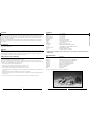 3
3
-
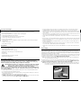 4
4
-
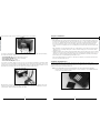 5
5
-
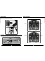 6
6
-
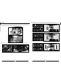 7
7
-
 8
8
-
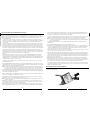 9
9
-
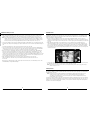 10
10
-
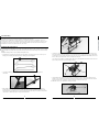 11
11
-
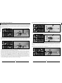 12
12
-
 13
13
-
 14
14
-
 15
15
-
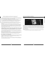 16
16
-
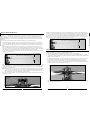 17
17
-
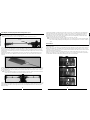 18
18
-
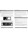 19
19
-
 20
20
-
 21
21
-
 22
22
-
 23
23
-
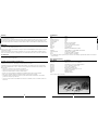 24
24
-
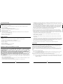 25
25
-
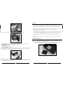 26
26
-
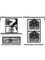 27
27
-
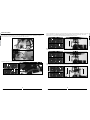 28
28
-
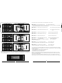 29
29
-
 30
30
-
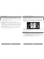 31
31
-
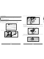 32
32
-
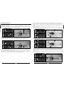 33
33
-
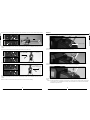 34
34
-
 35
35
-
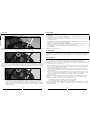 36
36
-
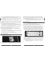 37
37
-
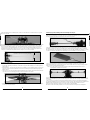 38
38
-
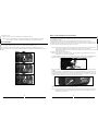 39
39
-
 40
40
-
 41
41
-
 42
42
-
 43
43
-
 44
44
-
 45
45
-
 46
46
-
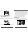 47
47
-
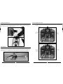 48
48
-
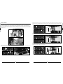 49
49
-
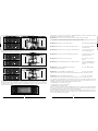 50
50
-
 51
51
-
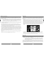 52
52
-
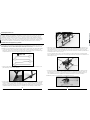 53
53
-
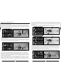 54
54
-
 55
55
-
 56
56
-
 57
57
-
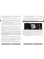 58
58
-
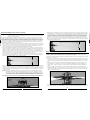 59
59
-
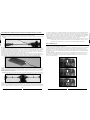 60
60
-
 61
61
-
 62
62
-
 63
63
-
 64
64
-
 65
65
-
 66
66
-
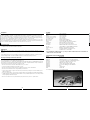 67
67
-
 68
68
-
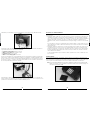 69
69
-
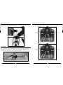 70
70
-
 71
71
-
 72
72
-
 73
73
-
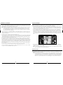 74
74
-
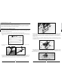 75
75
-
 76
76
-
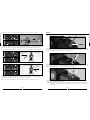 77
77
-
 78
78
-
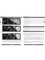 79
79
-
 80
80
-
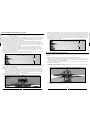 81
81
-
 82
82
-
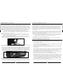 83
83
-
 84
84
-
 85
85
-
 86
86
-
 87
87


Blade SR Benutzerhandbuch
- Kategorie
- Ferngesteuertes Spielzeug
- Typ
- Benutzerhandbuch
in anderen Sprachen
- English: Blade SR User manual
- français: Blade SR Manuel utilisateur
- italiano: Blade SR Manuale utente
Verwandte Artikel
Andere Dokumente
-
E-flite Blade SR Benutzerhandbuch
-
Merlin POLARIS 400CP Benutzerhandbuch
-
-
BNF BLH3100 Benutzerhandbuch
-
protech ZOOM 450 ccpm Benutzerhandbuch
-
-
BMI 0461-000 Benutzerhandbuch
-
-
Carrera RC Micro Helicopter Bedienungsanleitung
-