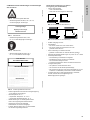
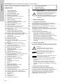
Grundfos Vaccuperm VGA-146 Installation And Operating Instructions Manual
- Typ
- Installation And Operating Instructions Manual

Vaccuperm VGA-146
Vacuum regulator
Installation and operating instructions
GRUNDFOS INSTRUCTIONS
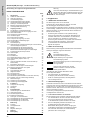
Other languages
http://net.grundfos.com/qr/i/95714278

2

Table of contents
3
Vaccuperm VGA-146
English (GB)
Installation and operating instructions . . . . . . . . . . . . . . . . . . . . . . . . . . . . . . . . . . . . . . . . . . . . . . . . . . . . . . . . . . . 4
Čeština (CZ)
Montážní a provozní návod . . . . . . . . . . . . . . . . . . . . . . . . . . . . . . . . . . . . . . . . . . . . . . . . . . . . . . . . . . . . . . . . . . 19
Deutsch (DE)
Montage- und Betriebsanleitung . . . . . . . . . . . . . . . . . . . . . . . . . . . . . . . . . . . . . . . . . . . . . . . . . . . . . . . . . . . . . . 34
Español (ES)
Instrucciones de instalación y funcionamiento. . . . . . . . . . . . . . . . . . . . . . . . . . . . . . . . . . . . . . . . . . . . . . . . . . . . 49
Français (FR)
Notice d'installation et de fonctionnement . . . . . . . . . . . . . . . . . . . . . . . . . . . . . . . . . . . . . . . . . . . . . . . . . . . . . . . 64
Polski (PL)
Instrukcja montażu i eksploatacji . . . . . . . . . . . . . . . . . . . . . . . . . . . . . . . . . . . . . . . . . . . . . . . . . . . . . . . . . . . . . . 79
Português (PT)
Instruções de instalação e funcionamento. . . . . . . . . . . . . . . . . . . . . . . . . . . . . . . . . . . . . . . . . . . . . . . . . . . . . . . 94
Română (RO)
Instrucţiuni de instalare şi utilizare . . . . . . . . . . . . . . . . . . . . . . . . . . . . . . . . . . . . . . . . . . . . . . . . . . . . . . . . . . . . 109
Русский (RU)
Паспорт, Руководство по монтажу и эксплуатации . . . . . . . . . . . . . . . . . . . . . . . . . . . . . . . . . . . . . . . . . . . . . 124
Türkçe (TR)
Montaj ve kullanım kılavuzu . . . . . . . . . . . . . . . . . . . . . . . . . . . . . . . . . . . . . . . . . . . . . . . . . . . . . . . . . . . . . . . . . 140
Declaration of conformity . . . . . . . . . . . . . . . . . . . . . . . . . . . . . . . . . . . . . . . . . . . . . . . . . . . . . . . . . . . . . . . . . . . 156
Declaration of conformity EAC . . . . . . . . . . . . . . . . . . . . . . . . . . . . . . . . . . . . . . . . . . . . . . . . . . . . . . . . . . . . . . . 157

English (GB)
4
English (GB) Installation and operating instructions
Original installation and operating instructions
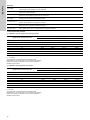
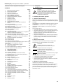
CONTENTS
Page
1. Of general interest
1.1 Structure of the documentation
The Grundfos dosing regulator VGA-146 is a state-of-the-art
solution, which complies with recognised safety regulations.
Conformity with applicable standards, directives and laws has
been verified.
Nevertheless, certain risks which cannot be prevented by the
manufacturer are associated with the use of the system.
Purpose of this manual:
• Inform users of optimum use.
• Warn users of possible residual risks when using correctly and
identify measures that should be taken to avoid damage.
• Caution users against obvious misuse or inappropriate use
and inform them of the necessary care that must be taken
when operating the system.
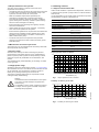
1.2 About this manual
This manual contains the following standardised safety
instructions about possible residual risks:
Information about possible residual risks is provided:
• On warning signs displayed in the installation location.
• At the start of each section in this manual.
• Directly before any operating procedures that could involve
residual risks.
1.3 User/target groups
Users are persons who are responsible for operating and
monitoring the device VGA-146 at the installation location. The
system may only be operated by trained and qualified personnel.
Personnel must have appropriate technical knowledge and be
familiar with the basic principles of measuring and control
technology.
1.3.1 Responsibilities of the users
The users’ responsibilities:
• Read this manual before operating the VGA-146.
• Be trained by qualified personnel from Grundfos in the
operation of the system.
• Observe the recognised regulations governing safety in the
workplace and accident prevention.
• Wear appropriate protective clothing in accordance with
national regulations for the prevention of accidents when
operating the system and handling chemicals (German
GUV-V D05).
1. Of general interest
4
1.1 Structure of the documentation
4
1.2 About this manual
4
1.3 User/target groups
4
1.3.1 Responsibilities of the users
4
1.4 Responsibilities of the operator
5
1.5 Maintenance and service personnel
5
1.6 Correct usage
5
1.7 Inappropriate usage
5
2. Handling chlorine
5
2.1 Physical and chemical data
5
2.2 Safety advice for handling chlorine
6
2.2.1 Risks to health
6
2.2.2 Personal safety equipment
6
2.2.3 Rules of conduct
6
2.2.4 First aid in case of accidents
6
2.2.5 Transport and storage of chlorine
6
2.2.6 Pressure vessels and mountings
7
2.2.7 Chlorine extraction
8
2.3 Checking the tightness
8
2.3.1 Checking the chlorine solution lines and the diaphragm
non-return of the injector
8
2.3.2 Checking the tightness of the vacuum lines
8
2.3.3 Checking the tightness of pressure gas lines
8
2.4 Constructional requirements of chlorination plants
9
2.5 Principle function of the components
10
2.5.1 Vacuum regulator
10
2.5.2 Measuring tube
10
2.5.3 Rate valve
10
2.5.4 Differential pressure regulator (Option: VGA-117)
10
2.5.5 Vacuummeter (Option: VGA-117)
10
2.5.6 Injector
10
2.6 List of valid laws and regulations
11
2.7 Recommended diameter
12
2.7.1 Between vacuum regulator and dosing regulator
12
2.7.2 Between dosing regulator and injector
12
3. Technical Data
13
3.1 Type key VGA-146
13
3.2 General Data
14
3.2.1 Pressure connection
14
3.2.2 Liquid trap (with heating)
14
3.2.3 Pressure gauge (limit contact for minimal admission
pressure)
14
3.2.4 Accessories (not including)
14
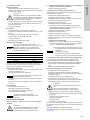
3.3 Dimensioned drawings
15
3.3.1 Design with liquid trap
15
3.3.2 Design with mounting plate
15
4. Installation
16
4.1 Transport and storage
16
4.2 Unpacking
16
4.3 Mounting
16
5. Commissioning
16
5.1 Preparations for commissioning
16
5.1.1 Vacuum connections
16
5.1.2 Pressure line connection
16
5.1.3 Electrical connections
16
5.2 Checks before commissioning
17
5.2.1 Checking the tightness of pressure gas lines
17
5.2.2 Checking the tightness with nitrogen
17
5.2.3 Checking the tightness with ammonia
17
6. Operation
17
6.1 Function
17
6.2 Display Elements
17
6.3 Operating
17
6.4 Possible faults
18
7. Maintenance
18
8. Disposal
18
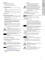
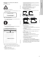
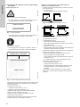
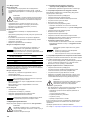
Warning
Prior to installation, read these installation and
operating instructions. Installation and operation
must comply with local regulations and accepted
codes of good practice.
Warning
If these safety instructions are not observed, it may
result in personal injury.
Caution
If these safety instructions are not observed, it may
result in malfunction or damage to the equipment.
Note
Notes or instructions that make the job easier and
ensure safe operation.

English (GB)
5
1.4 Responsibilities of the operator
The owner of the building or operator of the VGA-146 is
responsible for the following:
• Consider this manual to be part of the product and ensure that
it is kept clearly accessible in the immediate vicinity of the
system for the entire service life of the system.
• Meet the installation requirements specified by the
manufacturer (required water connections and fittings,
environmental conditions, electrical connection, protective
pipe for dosing line if necessary, audible or optical warning
device for alarm messages if necessary).
• Ensure that water lines and fixings are regularly checked,
serviced and maintained.
• Obtain official approval for storing chemicals, if necessary.
• Train users in the operation of the system.
• Ensure that the regulations for the prevention of accidents are
observed in the installation location (German GUV-V D05
regulation for the prevention of accidents, "Chlorination of
Water" dated January 1997).
• Provide all users and service personnel with protective
clothing in accordance with GUV-V D05 (face mask, gloves,
protective apron).
1.5 Maintenance and service personnel
The system may only be maintained and serviced by authorised
service personnel from Grundfos.
1.6 Correct usage
Grundfos VGA-146 may be used for reducing the pressure
(overpressure) of the gases chlorine (Cl
2
) to subatmospheric
pressure (vacuum) within systems for the processing of water,
within the scope of the possibilities for use described in this
manual.
The permitted dosing media depending on the design, is stated
on the type plate.
1.7 Inappropriate usage
Applications other than those listed in section 1.6 Correct usage
are considered not to be in accordance with the intended use and
are not permitted. The manufacturer, Grundfos, accepts no
liability for any damage resulting from incorrect use.
The system comprises state-of-the-art components and has
undergone safety-related testing.
2. Handling chlorine
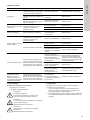
2.1 Physical and chemical data
Under normal conditions of pressure and temperature, chlorine is
a yellowish green gas with a pungent odour. It exists as diatomic
molecule Cl
2
.
It is not flammable, but can under certain circumstances promote
the flammability of metals, hydrocarbons etc.
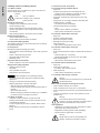
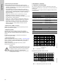
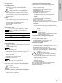
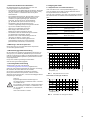
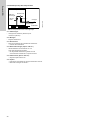
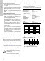
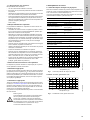
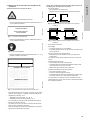
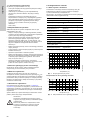
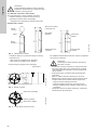
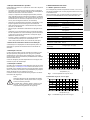
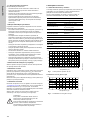
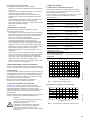
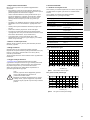
Vapour pressure curve of chlorine
Fig. 1 Vapour pressure curve of chlorine
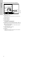
Solubility of chlorine gas in water
Fig. 2 Solubility of chlorine gas in water
Warning
Unauthorised structural modifications to the system
may result in serious damage to equipment and
personal injury.
It is forbidden to open, modify, change the structure
of, bridge, remove, bypass or disable components,
especially safety equipment.
Atomic weight 35,457
Molecular weight Cl
2
70,941
Density (liquid) 1,57 g/cm
3
at -34,05 °C
Density (gaseous) 3,214 g/l at 0 °C, 1 bar
1 l liquid chlorine at 0 °C
corresponds to 457 l (0,457 m
3
)
gaseous chlorine
1 kg liquid chlorine at 0 °C
corresponds to 311 l (0,311 m
3
)
gaseous chlorine
Specific gravity 2,486 (specific gravity of air: 1)
Boiling point - 34,05 °C (1 bar)
Melting point - 100,98 °C
Evaporation heat 269 kJ/kg (at 0 °C)
Heat conductivity 0,527 kJ/m
2
h (liquid chlorine)
Degree of purity acc. to DIN
19607
99,5 %
TLV (Threshold Limit Value) 1,5 mg/m
3
(0,5 Vol.-ppm)
TM04 0691 0908TM04 0692 0908
0
4
8
12
16
20
-50
-30
-10
0
10
30
50 70
Temperature (°C)
10
30
50
70
90
2
6
14
0
10
Temperature (°C)

English (GB)
6
2.2 Safety advice for handling chlorine
2.2.1 Risks to health
Chlorine gas is toxic, more than 50 Vol.-ppm in the indoor air
mean an acute danger to life.
Hazards of chlorine gas
• Irritating to eyes, respiratory system and skin.
• Causes whooping cough.
• Causes causticization of skin and respiratory system.
• Lethal by lung edema in case of long influence or high
concentration.
• Slight paralyzing effect to the central nervous system.
Hazards of liquid chlorine
• Causes causticization of skin.
• Causes reddening and formation of bubbles.
2.2.2 Personal safety equipment
The operating authority of a chlorination plant has to provide for
the operation personnel:
For each person
Respiratory equipment (full-sight gas mask)
• with an effective chlorine filter (B2P3), colour mark: grey with a
white ring
• at least 1 spare filter per gas mask
• personally fitted (perfectly tight)
• labelled by name
Only plants with chlorine drums
• at least 2 protective suits with compressed air respirators
Storage of the safety equipment
• outside the chlorine rooms
• well visible
• easily available at any time
• protected from dust and moisture
• Introducing the operation personnel to handle the safety
equipment
• Carrying out exercises (at least half-yearly)
• Regular replacement of the gas mask filters
– after the expiry of the date of durability
– at least 6 months after opening (mark the opening date on
the filter)
– after contact with chlorine
– Observe employing prohibition according to § 14 ArbStoffV
(in Germany) resp. according to local laws!
2.2.3 Rules of conduct
• Change of chlorine containers only with gas mask.
• Entering contaminated rooms only with protective suit and
compressed air respirator.
• In case of flight wear gas mask, if possible. Observe wind
direction!
• Eating, drinking and storing food is prohibited in chlorine
rooms.
2.2.4 First aid in case of accidents
First aid after having inhalated chlorine
• Keep calm.
• Remove injured persons from the dangerous area.
– Helpers must pay attention to personal protection!
• Immediately remove contaminated clothes.
• Calm down injured persons and keep them warm with
blankets.
• Supply fresh air; use oxygen respirator (alternately with
inhalating steam), if possible.
– No mouth-to-mouth resuscitation!
• Fast and gentle transport to hospital
– lying
– sitting in case of difficulty in breathing
– state chlorine causticization as the cause.
First aid after causticization of the skin
• Keep calm.
• Remove contaminated clothes.
• Rinse skin with plenty of water
• Bandage the wound germ-freely
• Seek medical aid.
– State chlorine causticization as the cause.
First aid after causticization of the eyes
• Keep calm.
• Rinse causticized eyes with plenty of water while the person is
lying.
– Protect healthy eye, if necessary.
– Spread eyelids widely, let the eye move to all sides.
• Seek ophthalmologist.
– State chlorine causticization as the cause.
First aid after internal causticization
• Keep calm.
• Drink water in short sips.
– If possible, take medical charcoal.
• Seek medical aid.
– state chlorine causticization as the cause.
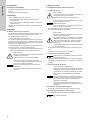
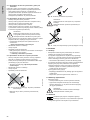
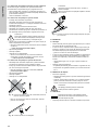
2.2.5 Transport and storage of chlorine
Basic rules for transport and storage of chlorine
• Treat containers carefully, do not throw!
• Protect containers from turning over or rolling away!
• Protect containers from direct sun rays and temperatures over
50 °C!
• Transport of containers only with valve protection nut and
protection cap.
Valid regulations
– Regulations for accident prevention "Chlorination of water"
(GUV-V D5) with process instructions
– Regulations concerning places of work (ArbStättV))
– Technical rules for gases 280, 310 und 330
Warning
R 23 Toxic by inhalation.
R 36/37/38 Irritating to eyes, respiratory
system and skin.
Caution
Further obligations of the operating authority
Warning
Handling of chlorine containers only by experienced,
practised personnel!
Warning
This rules are valid for both full and empty
containers, as empty containers still contain rests of
chlorine and therefore are under pressure.
Warning
Strictly observe local law and regulations for
handling, transport and storage of chlorine.

English (GB)
7
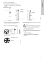
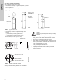
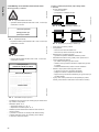
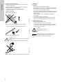
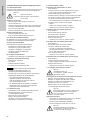
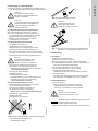
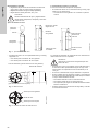
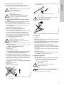
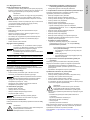
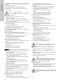
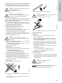
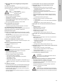
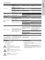
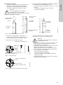
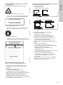
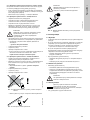
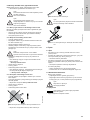
2.2.6 Pressure vessels and mountings
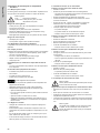
Chlorine is being offered in two container designs:
• Steel cylinders containing 50 kg or 65 kg, equipped with one
valve for
– the withdrawal of gaseous chlorine from the upright standing
cylinder
Variant of chlorine cylinder
Fig. 3 Variant of chlorine cylinder
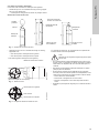
• Steel drums containing 500 kg or 1000 kg, equipped with
– one valve for the withdrawal of gaseous chlorine
– one valve for the withdrawal of liquid chlorine
Fig. 4 Chlorine drum
Fig. 5 Valve position of chlorine drum
Due to safety precautions, chlorine containers are only filled up to
95 % of their capacity.
• Kind of gas, weight, owner, producing date and date of the last
testing have to be noted clearly on the container. Chlorine
containers are marked by grey colour.
• No changes or repair by the user!
• Never open container valves by force. Stuck valve spindels
can be loosened by wrapping a shred with warm water around
the valve.
– Never use an open flame!
– Never use wrench lengthening!
– Return containers with stuck valves to the manufacturer.
• Observer safety precautions and the manuals of the
manufacturer!
TM04 0693 0908
Protecting cap
Valve
Holding clip
Valve thread acc.
to DIN 477
Labelled by
stamping
Weldless chlorine
cylinder
Aluminium
label
Welded chlorine
cylinder
TM04 0694 0908TM04 0695 0908
2
5
3
6
4
1
3
4
Tyre of roller
Riser pipe (for the withdrawal of gaseous chlorine)
Protecting cap
Valves
dip pipe
(for the withdrawal of liquid chlorine)
Valve for gaseous chlorine
Colour ring
Valve for liquid chlorine
Warning
Observe safety precautions for chlorine containers

English (GB)
8
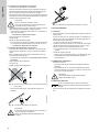
2.2.7 Chlorine extraction
Before the extraction
• The chlorine containers must be stored at least for 8 hours in
the container room so that the content can adapt the ambient
temperature.
• Turn chlorine drums on the support until the dip pipe and the
riser pipe are placed vertically (observe the markings on the
drum).
• Check tightness.
Connection
• Protect containers from turning over or rolling away!
• Dry the piping and the withdrawal system with dry nitrogen or
dry air.
• No foreign matter must get into the plant.
• Mount new gaskets to the connection line.
• Connect the container.
• Slowly open the container valve.
Withdrawal of gaseous chlorine
In case of higher chlorine requirement several chlorine containers
of the same temperature have to be connected with header lines.
Withdrawal of liquid chlorine
• Within chlorination plants only possible from chlorine drums.
• Application of an evaporator is necessary.
• Withdrawal of gaseous chlorine: Observe residual pressure of
ca. 2 bar.
• Withdrawal of liquid chlorine: Observe residual pressure of ca.
4 bar.
After the extraction
• Close container valve.
• Disconnect container from the plant.
• Screw on valve protection nuts.
• Screw on protection cap.
2.3 Checking the tightness
Before commissioning check the tightness of the whole plant.
2.3.1 Checking the chlorine solution lines and the diaphragm
non-return of the injector
• Observe the manual of the injector!
2.3.2 Checking the tightness of the vacuum lines
Vacuum lines are all lines between vacuum regulator and injector.
• Close all container valves
• Close the rate valve
• Open the shut-off valve at the injection unit
• Open motive water valve
• Switch on the booster pump
• Open the rate valve
– Floater shows gas flow or vacuummeter shows more than -
9 m w. c.: Leakage in vacuum line!
• Close rate valve
• Switch off booster pump
• Close motive water valve
• Close the shut-off valve at the injection unit
• Check the vacuum lines and the connection. If necessary,
carefully re-tighten them.
• Check tightness again!
– Floater shows no gas flow, vacuummeter shows -9 m w. c.
or less: Vacuum lines are tight.
2.3.3 Checking the tightness of pressure gas lines
Pressure gas lines are all lines from the gas containers to the
vacuum regulator.
• If the plant is equipped with a nitrogen rinsing device: Check
tightness roughly with nitrogen
• Detailed checking with ammonia
Checking the tightness with nitrogen
• Close all container valves
• Open container connection valves and all shut-off valves up to
the gas dosing system
• Open the connection valve of the nitrogen cylinder
• Slowly open the valve of the nitrogen cylinder, until the lines
have a pressure of about 10 bar (read at the manometer of the
vacuum regulator).
• Apply soap water to all components under pressure
– Formation of bubbles and/or pressure drop at manometer
Leakage in pressure lines!
– Depressurize the plant!
– Eliminate leakage!
– Check tightness again!
No formation of bubbles, pressure at manometer does not drop
significantly within one hour: Pressure lines are tight.
Checking the tightness with ammonia
See chapter 5.2.3 Checking the tightness with ammonia.
Warning
Chlorine containers must never have a higher
temperature than other parts of the plant. Danger of
liquefaction and possible chlorine break-out!
Caution
At 15 °C about 1 % (DIN19607) of the content can be
withrawn per hour. In case of higher withdrawal
danger of malfunction by the formation of ice on
containers and piping!
Container size Withdrawal quantity
50 Kg 500 g/h
65 Kg 650 g/h
500 Kg 5 Kg/h
1000 Kg 10 Kg/h
Caution
Do not completely evacuate the chlorine drums.
Danger of withdrawing deposits!
Caution
Immediately close connection lines.
No moisture must get into the lines!
Warning
Do not check the tightness until the whole plant is
ready for start-up.
Danger of chlorine break-out!
Note
More possible reasons for insufficient operating
vacuum
• injector layed out too weakly or defective
• injector obstructed
• booster pump layed out too weakly or defective
Warning
Maximum nitrogen pressure 16 bar!
Danger of damages and gas leakage when being
exceeded!

English (GB)
9
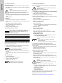
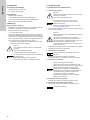
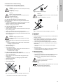
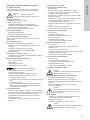
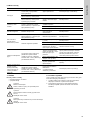
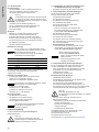
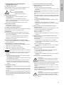
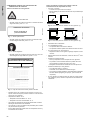
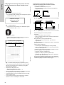
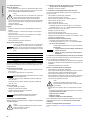
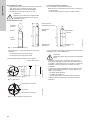
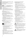
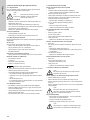
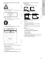
2.4 Constructional requirements of chlorination plants
All chlorine rooms
Fig. 6 Warning sign DIN 4844
– Warning sign according to DIN 4844 part 1 no. 4.2, to be
installed at entrances
Fig. 7 Supplementary sign
– Supplementary sign according to DIN 4844 part 1 no. 4.5, to
be installed at entrances
Fig. 8 Mandatory sign
– Mandatory sign according to DIN 4844 part 1 no. 4.3, to be
installed inside the rooms
Fig. 9 Instruction sheet for first aid
• Instruction sheet for first aid in case of chlorine gas
intoxications, to be installed inside the rooms
• Maximum temperature: 40 °C
– recommended temperature: 18 - 20 °C
– recommended minimal temperature: 15 °C
• Overpressure lines of dosing equipment must not end in the
open air
• Chlorine rooms must not be dedicated for the permanent stay
of people.
• Only chlorine containers and the chlorination plant may be
present in the rooms.
Rooms with pressure lines (e. g. storage rooms for chlorine
containers)
• Flat, even floor
– not below ground level
– not higher than a possible loading ramp
Fig. 10 Regulations for chlorine rooms (1)
Fig. 11 Regulations for chlorine rooms (2)
• Direct exit to the open air
• Lockable
– doors must open outwards
– it must be possible to open the doors without a key from
inside the room
• No connection to other rooms
– separated gastight and fire-resistant from other rooms
• A maximum of two vent holes of max. 20 cm
2
each
• Water sprinkling system
– for precipitating escaping chlorine gas
– operation must be possiple by hand from outside the
chlorine rooms
– sufficiently dimensioned run-off with air trap
• Chlorine gas warning system
– with optical and acoustical alarm
– coupled to the water sprinkling system
– coupling must reactivate automatically after having switched
off (e. g. for container exchange)
• Chlorine gas must not be able to get into lower-lying rooms,
shafts, pits, canals or aspirating holes of ventilation systems.
TM04 0699 0908TM04 0700 0908TM04 0701 0908TM04 0702 0908
Chlorination unit
Acces only for
instructed persons
asdajlk llasdf lalsdk lasdlfkl lasdkjasdlklj jlakjlkjdl alsdfkljkj asdlklk lalsdk asdajlk llasd f lalsdk lasdlfkl lasdkjasdlklj jlakjlkjdl alsdfkljkj
sdk asdajlk llasdf lalsdk lasdlfkl lasdkjasdlklj jlakjlkjdl alsdfkljkj asdlklk lalsdk asdajlk llasdf lalsdk lasdlfkl lasdkjasdlklj jlakjlkjdl alsdfkljkj
asdajlk llasdf lalsdk lasdlfkl lasdkjasdlklj jlakjlkjdl alsdfkljkj asdlklk lalsdk asdajlk llasd f lalsdk lasdlfkl lasdkjasdlklj jlakjlkjdl alsdfkljkj
asdajlk llasdf lalsdk lasdlfkl lasdkjasdlklj jlakjlkjdl alsdfkljkj asdlklk lalsdk asdajlk llasd f lalsdk lasdlfkl lasdkjasdlklj jlakjlkjdl alsdfkljkj
asdajlk llasdf lalsdk lasdlfkl lasdkjasdlklj jlakjlkjdl alsdfkljkj asdlklk lalsdk asdajlk llasd f lalsdk lasdlfkl lasdkjasdlklj jlakjlkjdl alsdfkljkj
asdajlk llasdf lalsdk lasdlfkl lasdkjasdlklj jlakjlkjdl alsdfkljkj asdlklk lalsdk
asdajlk llasdf lalsdk lasdlfkl lasdkjasdlklj jlakjlkjdl alsdfkljkj asdlklk lalsdk asdajlk llasd f lalsdk lasdlfkl lasdkjasdlklj jlakjlkjdl alsdfkljkj
asdajlk llasdf lalsdk lasdlfkl lasdkjasdlklj jlakjlkjdl alsdfkljkj asdlklk lalsdk asdajlk llasd f lalsdk lasdlfkl lasdkjasdlklj jlakjlkjdl alsdfkljkj
asdajlk llasdf lalsdk lasdlfkl lasdkjasdlklj jlakjlkjdl alsdfkljkj asdlklk lalsdk asdajlk llasd f lalsdk lasdlfkl lasdkjasdlklj jlakjlkjdl alsdfkljkj
k asdajlk llasdf lalsdk lasdlfkl lasdkjasdlklj jlakjlkjdl alsdfkljkj asdlklk lalsdk asdajlk llas df lalsdk lasdlfkl lasdkjasdlklj jlakjlkjdl alsdfkljkj
sdk asdajlk llasdf lalsdk lasdlfkl lasdkjasdlklj jlakjlkjdl alsdfkljkj asdlklk lals
asdajlk llasdf lalsdk lasdlfkl lasdkjasdlklj jlakjlkjdl alsdfkljkj asdlklk lalsdk asdajlk llasd f lalsdk lasdlfkl lasdkjasdlklj jlakjlkjdl alsdfkljkj
asdajlk llasdf lalsdk lasdlfkl lasdkjasdlklj jlakjlkjdl alsdfkljkj asdlklk lalsdk
asdajlk llasdf lalsdk lasdlfkl lasdkja
asdajlk llasdf lalsdk lasdlfkl lasdkjasdlklj jlakjlkjdl alsdfkljkj asdlklk lalsdk asdajlk llasd f lalsdk lasdlfkl lasdkjasdlklj jlakjlkjdl alsdfkljkj
asdajlk llasdf lalsdk lasdlfkl lasdkjasdlklj jlakjlkjdl lalsdk
sdk asdajlk llasdf lalsdk lasdlfkl lasdkjasdlklj jlakjlkjdl alsdfkljkj asdlklk lalsdk asdajlk llasdf lalsdk lasdlfkl lasdkjasdlklj jlakjlkjdl alsdfkljkj
First aid in the case of
CHLORINE GAS POISONNING
HEALTH DANGERS
FIRST AID
TM04 0703 0908TM04 0704 0908
✓
✗
✗

English (GB)
10
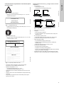
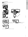
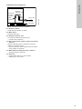
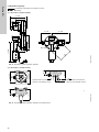
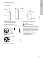
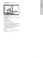
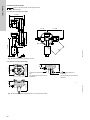
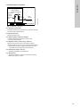
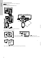
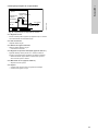
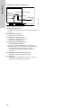
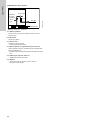
2.5 Principle function of the components
Fig. 12 Components of a chlorinator
2.5.1 Vacuum regulator
• Reduces the gas pressure (overpressure) to subatmospheric
pressure (vacuum)
2.5.2 Measuring tube
• Displays the gas flow
2.5.3 Rate valve
• For adjustment of the required gas flow
– manually or automatically
2.5.4 Differential pressure regulator (Option: VGA-117)
• Regulates the difference of the pressures before and after the
rate valve to a constant value
– Adjusted dosing flow stays constant even when the injector
vacuum varies.
2.5.5 Vacuummeter (Option: VGA-117)
– Displays the injector vacuum
2.5.6 Injector
– Creates the vacuum necessary for operating the pant
– Mixes the chlorine gas with the water
TM04 0705 0908
Motive water
Vacuum regulator
Measuring
tube
Gas Dosing System
Differential
pressure
regulator
Vaccum
meter
Injector
Rate Valve
Chlorine gas

English (GB)
11
2.6 List of valid laws and regulations
Laws and Regulations
DVGW-Rules
BGBl. I 1975 S. 729
Verordnung über Arbeitsstätten (Arbeitsstättenverordnung - ArbStättV)
Regulations concerning places of work (ArbStättV)
BGBl I 1980 S. 173,
184
Verordnung über Druckbehälter, Druckgasbehälter und Füllanlagen (Druckbehälterverordnung - DruckbehV) mit
technischen Regeln Druckbehälter (TRB) mit technischen Regeln Druckgase (TRG)
Regulations concerning pressure containers, gas cylinders and filling systems (pressure containers - DruckbehV)
with technical rules for pressure containers (TRB) with technical rules for pressure gases (TRG)
BGBl I 1986 S. 1470
Gefahrstoffverordnung (GefStoffV)
Regulations for hazardous materials (GefStoffV)
BGBl I 1975 S. 2494
Verordnung über gefährliche Arbeitsstoffe (Arbeitsstoffverordnung - ArbStoffV)
Regulations for hazardous work materials (ArbStoffV)
GUV 0.1
Unfallverhütungsvorschrift "Allgemeine Vorschriften"
Regulations for accident prevention "General Regulations"
GUV-V D5
Unfallverhütungsvorschrift "Chlorung von Wasser"
Regulations for accident prevention "Chlorination of water"
GUV 49.1
Prüfliste zur Unfallverhütungsvorschrift "Chlorung von Wasser"
Checklist for Regulations for accident prevention "Chlorination of water"
GUV 0.3
Unfallverhütungsvorschrift "Erste Hilfe"
Regulations for accident prevention "First-Aid"
GUV 20.5
Merkblatt "Anleitung zur ersten Hilfe bei Unfällen"
Leaflet "Instructions for First-Aid in case of accidents"
GUV 20.6
Merkblatt "Verbandzeug für die erste Hilfe bei Unfällen"
Leaflet "Dressing material for First-Aid in case of accidents"
GUV 20.14
Atemschutzmerkblatt
Leaflet for the protection of the air
GUV 29.6
Merkblatt "Über den Umgang mit ätzenden Stoffen"
Leaflet "Handling of caustic materials"
GUV 60.3G26
Grundsatz für arbeitsmedizinische Vorsorgeuntersuchungen "Träger von Atemschutzgeräten für Arbeit und
Rettung" G 26
Principle for preventive industrial medicine checkup "Wearers of respiratory equipment for work and rescue" G 26
GUV 2.6
Unfallverhütungsvorschrift "Druckbehälter"
Regulations for accident prevention "Pressure containers"
GUV 2.10
Unfallverhütungsvorschrift "Elektrische Anlagen und Betriebsmittel"
Regulations for accident prevention "Electrical installations and resources"
GUV 9.9
Unfallverhütungsvorschrift "Gase"
Regulations for accident prevention "Gases"
ZH1/230
Merkblatt "Chlor"
Leaflet "Chlorine"
CEFIC
Unfallmerkblatt für den Straßentransport "Chlor" Klasse 2, Ziffer 3 at UN 2201
Accident leaflet for the road transport "Chlorine" Class 2, Number 3 at UN 2201
BGBl I 1985, S. 1550
Verordnung über die Beförderung gefährlicher Güter auf der Straße - Gefahrgut Vstr/GGVS - Klasse 2, Ziffer 3 at
Regulations for the transport of dangerous goods on the road - Gefahrgut Vstr/GGVS - Class 2, Number 3 at
GGVE
Gefahrgutverordnung Eisenbahn, Klasse 2, Ziffer 3 at)
Regulations for dangerous goods on trains, Class 2, Number 3 at)
RID
Internationale Verordnung für die Beförderung gefährlicher Güter mit der Eisenbahn - Klasse 2, Ziffer 3 at
International regulations for the transport of dangerous goods by train - Class 2, Number 3 at
BGBl I 1977, S. 1119
Verordnung über die Beförderung gefährlicher Güter auf dem Rhein (ADNR)
Regulations for the transport of dangerous goods on the Rhine (ADNR)
W203
Begriffe der Chlorung
Concept of chlorination
W645-1
Überwachungs-, Mess-, Steuer- und Regeleinrichtungen in Wasserversorgungsanalagen
Devices for monitoring, measuring, control and regulation in water supply plants
W291
Desinfektion von Wasserversorgungsanlagen
Disinfection of water supply plants
W623
Dosieranlagen für Desinfektions- bzw. Oxidationsmittel - Dosieranlagen für Chlor
Dosing units for disinfection or oxidation with chlorine
W640
Überwachungs-, Meß-, Steuer- und Regeleinrichtungen in Wasserwerken
Systems for monitoring, measurement, control and regulation in waterworks
DVGW-Merkblatt Arbeitshilfe zur Erstellung einer örtlichen Betriebsanweisung für Chlorungsanlagen unter
Verwendung von Chlorgas
DVGW leaflet Aid for the creation of a local manual für chlorination systems using chlorine gas

English (GB)
12
Standards
2.7 Recommended diameter
2.7.1 Between vacuum regulator and dosing regulator
Grundfos company standard calculated with pressure drop
p = 12.5 mbar
The indications in this table result from pressure loss
observations. They do not take into consideration the possible
influence of length and diameter of lines on the operational
reliability of the system.
2.7.2 Between dosing regulator and injector
Grundfos company standard calculated with pressure drop
p = 50 mbar
The indications in this table result from pressure loss
observations. They do not take into consideration the possible
influence of length and diameter of lines on the operational
reliability of the system.
DIN 19606
Chlorgasdosieranlagen zur Wasseraufbereitung
Chlorine gas dosing systems for water treatment
DIN 19607
Chlor zur Wasseraufbereitung
Chlorine for water treatment
DIN EN 937
Chlor zur Aufbereitung von Wasser für den menschlichen Gebrauch
Chlorine for the treatment of water for the human use
DIN 19643
Aufbereitung von Schwimm- und Badewasser
Treatment of swimming pool and bathing water
DIN 3179, Teil 1,2
Einteilung der Atemgeräte, Übersicht
Division of the respiratory equipment, overview
DIN 4102, Teil 2
Brandverhalten von Baustoffen und Bauteilen
Behaviour in fire of building materials and parts
DIN 477, Teil 1
Gasflaschenventile; Bauformen, Baumaße, Anschlüsse, Gewinde
Gas cylinder valves; forms, measurements, connections, threads
Length of the vacuum line in (m)
Dosing quantity (g/h)
1000 2000 4000 10000
0 DN 8 DN 8 DN 10 DN 15
10 DN 8 DN 8 DN 10 DN 15
20 DN 8 DN 10 DN 15 DN 20
30 DN 8 DN 10 DN 15 DN 20
40 DN 8 DN 15 DN 15 DN 20
50 DN 10 DN 15 DN 15 DN 20
75 DN 10 DN 15 DN 15 DN25
100 DN 10 DN 15 DN 20 DN25
Length of the vacuum line in (m)
Dosing quantity (g/h)
1000 2000 4000 10000
0 DN 8 DN 8 DN 8 DN 15
10 DN 8 DN 8 DN 8 DN 15
20 DN 8 DN 8 DN 10 DN 15
30 DN 8 DN 8 DN 10 DN 15
40 DN 8 DN 8 DN 10 DN 15
50 DN 8 DN 10 DN 15 DN 15
75 DN 8 DN 10 DN 15 DN 20
100 DN 8 DN 10 DN 15 DN 20

English (GB)
13
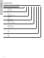
3. Technical Data
3.1 Type key VGA-146
Example: Vacuum regulator Type key VGA-146-D/1/6-S-0RF
Code Example VGA-146 -D /1 /6 -S -0 R F
Vaccuperm Gas Advanced = VGA
Installation
D Directly on the drum
W Wall-mounting
C Header line
Connection
1G 1
2G 3/4
3US yoke
4 Copper pipe 6/8 (G 1/2)
Connection output
5PE 8/11
6PE 10/14
7 PVC pipe DN 15
Inlet valve
SShort
L Long, 230-240 V/50-60 Hz
M Long, 110-115 V/50-60 Hz
Pressure indication
0 Without pressure gauge
1 Pressure gauge without contacts
2 Pressure gauge with MIN "NO"
3 Pressure gauge with MIN "NC"
Connection pressure gauge
TTop
R Right-hand-side
L Left-hand-side
F Front
Pressure inlet
F Front
L Left
R Right

English (GB)
14
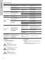
3.2 General Data
3.2.1 Pressure connection
3.2.2 Liquid trap (with heating)
3.2.3 Pressure gauge
(limit contact for minimal admission pressure)
3.2.4 Accessories (not including)
Permissible medium Cl
2
Flow range 0.2 - 10 kg/h, 10 - 530 lbs/day
Max. ambient temperature 40 °C
Minimal admission pressure 2 bar
Maximum admission pressure 11 bar
Pressure line connection
(inlet)
G3/4, G1, Cu pipe 6/8, USA
yoke
Vacuum line connection
(outlet)
PE 10/14, PVC pipe DN 15
Overpressure valve
connection
PE hose 8/11
Overpressure line to be used PE hose 8/11
Voltage
VGA-146-X/X/X/L-
0XX:
230 V, 50/60 Hz
VGA-146-X/X/X/M-
0XX:
115 V, 50/60 Hz
Mains cable
length 1.5 m euro plug (for 230 V) or USA
plug (for 115 V)
Power consumption 12 W
Degree of protection IP54
Temperature max. 60 °C, self-regulating
Measuring range 0-16 bar
Switch point
adjusted to the permissible minimal
admission pressure (2 bar)
Switching
performance
contact opens in case of decreasing the
adjusted switching point
Maximum switching
capacity
10 W for DC, 10 VA for AC
Maximum switching
voltage
100 V, DC or AC
Maximum switching
current
0.5 A for DC or AC, in case of pure
ohmic load
Switching hysteresis max. 2.5 %
Temperature range -30 °C up to +75 °C
Connection
2 wires, arbitrary polarity, length of the
cables about 3 m each
With holding plate for wall fixing at change of container
Installation material in 3 lengths
Test medium for leak search

English (GB)
15
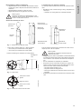
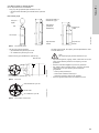
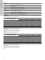
3.3 Dimensioned drawings
3.3.1 Design with liquid trap
Fig. 13 Dimensional drawing vacuum regulator
3.3.2 Design with mounting plate
Fig. 14 Dimensional drawing vacuum regulator on mounting plate
Note
According to the design, the measures may vary
slightly.
TM04 0844 0908
ca. 180
ca. 127
ca. 127
ca. 119
ca. 198
ca. 172
ca. 236
M6
150
TM04 0845 0908
ca. 173
ca. 126
ca. 62
ca. 54
ca. 200
ca. 160
ca. 86
pressure connection on the right
(gas valve facing left)
pressure connection on the left
(gas valve facing right)

English (GB)
16
4. Installation
4.1 Transport and storage
• Handle with care, do not throw!
• Dry and cool storage place.
4.2 Unpacking
• Observe when unpacking:
– No humidity should get into gas-leading parts!
– No foreign matter should get into gas-leading parts!
• Mount as soon as possible after unpacking.
4.3 Mounting
Requirements for mounting
• Installations at the pressure side from the containers resp. the
evaporator are present and checked for tightness
• Piping has been rinsed with nitrogen
– no more soiling present
• In case of design without liquid gas trap and for mounting to
header lines: Filter and liquid gas trap resp. pressure reducing
valve has been installed directly before the vacuum regulator
• Directly before the vacuum regulator the highest temperature
in the course of the pressure gas lines is present.
– If necessary, wrap a heater band around the pressure line
connection of the vacuum regulator.
5. Commissioning
5.1 Preparations for commissioning
5.1.1 Vacuum connections
• At the vacuum regulator, connect the vacuum line and connect
it to the dosing regulators.
• Connect the overpressure line to the overpressure connection.
• Connect the vacuum line to the injector.
5.1.2 Pressure line connection
• Slightly apply grease to the gasket, if necessary
• Connect the pressure line to the pressure line connection
5.1.3 Electrical connections
Connecting the liquid trap (option)
• Connect mains cable of the liquid trap with the mains
Connecting the contact manometer (option)
• Connect two cables with an external evaluation device
Warning
Ensure that all container valves are closed before
mounting.
Only use the intended line types!
Caution
In case of design without mounting plate:
The device will only be carried by the connection with
the pressure line.
Ensure that all piping is free of distortion.
Do not mount the device in a distorted manner.
Warning
Before connecting, ensure that the valves of all gas
containers are closed.
Only use the intended line types!
Caution
Only tighten the union nuts of the vacuum
connections by hand. Do not use any tools!
Danger of damages!
Maximum length of the vacuum line, see chapter
2.7 Recommended diameter
Warning
Lead the overpressure line downwards, as chlorine is
heavier than air.
Connect the overpressure line to a suitable
adsorption device. If using a gas warning device:
Mount the sensor in a distance of about 10 cm from
the outlet hole of the adsorption device.
The overpressure line must end in the room, never
lead to the open air!
Note
Ensure that the pressure lines are as short as
possible.
Caution
Before connecting the mains cable:
Check if the mains voltage indicated on the type
plate corresponds to the local mains voltage. Wrong
voltage can lead to damages of the product!
To ensure electromagnetic compatibility (EMC):
Signal lines must be shielded. The shield must be
connected to PE or ground on the side of the
counterpart, par exemple a controller.
Signal lines and mains lines must be guided in
different cable channels.
Note
The polarity is arbitrary.

English (GB)
17
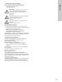
5.2 Checks before commissioning
Check tightness of the total plant before start-up.
– Observe manual of the gas dosing regulators!
5.2.1 Checking the tightness of pressure gas lines
Pressure gas lines are all lines from the gas containers to the
vacuum regulator.
• If the plant is equipped with a nitrogen rinsing device: Check
tightness roughly with nitrogen (all dosing media)
• Detailed checking: with ammonia
5.2.2 Checking the tightness with nitrogen
• Close all container valves
• Open container connection valves and all shut-off valves up to
the gas dosing system
• Open the connection valve of the nitrogen cylinder
• Slowly open the valve of the nitrogen cylinder, until the lines
have a pressure of about 10 bar (read at the manometer of the
vacuum regulator).
• Apply leakage spray or soap water to all components under
pressure
– Formation of bubbles and/or pressure drop at manometer
-->Leakage in pressure lines!
• Depressurize the plant!
• Eliminate leakage!
• Check tightness again!
– No formation of bubbles, pressure at manometer does not
drop significantly within one hour
--> Pressure lines are tight.
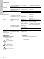
5.2.3 Checking the tightness with ammonia
• Open all container valves and container connection valves and
quickly close them again
• Slowly pass the open ammonia bottle along pressure-gas
leading parts
– Formation of white mist: Leakage in pressure lines!
• Depressurize the plant!
• Eliminate leakage!
• Check tightness again!
Fig. 15 Formation of white mist: Leakage in pressure lines!
– No formation of white mist: Pressure lines are tight.
Fig. 16 Pressure lines are tight
Fig. 17 Liquid ammonia makes leakages by corrosion
6. Operation
6.1 Function
• Reducing the gas pressure (overpressure) to subatmospheric
pressure (vacuum)
• In case of too high pressure in the device (e. g. if the inlet
valve is soiled or damaged) the overpressure valve opens.
– Gas will be lead to the absorption vessel.
• In case of the gas container getting empty or blocked gas
supply (too high vacuum in the device) the vacuum shut-off
valve closes.
– Gas containers will not be evacuated with the injector
vacuum.
• Liquid trap (option)
– Prevents liquid gas from getting into the vacuum regulator
– The temperature is self-regulating to max. 60 °C.
6.2 Display Elements
• Pressure gauge (option)
– displays the gas pressure at the inlet (admission pressure)
– optionally with a limit contact for minimal admission
pressure, e.g. empty signal is sent to the control panel.
6.3 Operating
• Observe manuals of the other components.
Warning
Check the tightness not until the total plant is ready
for start-up.
Danger of gas leakage!
Warning
Before checking the tightness:
Start running the optional built-in liquid trap or the
seperate liquid trap!
Danger of gas leakage!
Warning
Maximum nitrogen pressure 16 bar!
Danger of damages and gas leakage when being
exceeded!
TM04 0849 0908
TM04 0697 0908
Warning
Liquid ammonia must not come in contact with parts
of the plant!
Danger of leakages by corrosion!
TM04 0698 0908
Warning
Do not exceed the admission pressure!
Danger of gas break-out!
Note
The device is passive. All adjustment has to be made
at other parts of gas break-out!

English (GB)
18
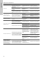
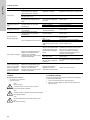
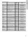
6.4 Possible faults
7. Maintenance
Rates for cleaning and maintenance
– at least every 12 months
– in case of malfunction
8. Disposal
This product or parts of it must be disposed of in an
environmentally sound way:
1. Use the public or private waste collection service.
2. If this is not possible, contact the nearest Grundfos company
or service workshop.
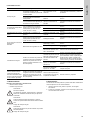
Fault To be recognized by Cause Correction
Gas leakage
Gas odour
Formation of mist at the connections
when checking the tightness
Connections not tight Check connections and retighten them
Gas escapes at the overpressure
line while the plant is not running
Inlet valve not tight Call the service
Loss of pressure at the manometer
while the plant is not running and
the gas supply is closed
Inlet valve or connections
not tight
Call the service
Overpressure valve not
tight
Vacuum present in the overpressure
line while the plant is running (to be
felt by putting on a finger)
Spring corroded or soiled Call the service
O-ring (19) defective Replace o-ring (19)
Diaphragm defective Call the service
Disturbed regulation
Vibrations and booming of the
device
Diaphragm distored or
mounted incorrectly
Call the service
Desired dosing flow is
not
reached
Vacuum present in the overpressure
line while the plant is running (to be
felt by putting on a finger)
Diaphragm damaged Call the service
Pressure gauge of the vacuum
regulator
Admission pressure too low
(< 2 bar)
Call the service
Gas container empty Replace gas containers by full ones
Shut-off valves in the
pressure lines closed or not
perfectly open
Open the shut-off valves
Re-liquefaction of the
gas
Formation of ice on filter or pressure
line connection during start-up,
damages of PVC enclosure parts
(only visible when the device is
open)
Temperature at the pressure
line connection lower than
the temperature of the other
pressure gas lines
Wrap a heater band around the filter and/
or the pressure line connection and warm
them up. Close gas supply before the
filter, adjust the gas dosing system to
minimal dosing flow and start the plant
Heating of the liquid trap not
connected or defective
Call the service
Vacuum regulator without
liquid trap used with gas
drum
Use a vacuum regulator with a liquid trap
External evaluation
device shows
mistakenly too low
admission pressure
(only for the optional
contact manometer
Formation of ice on filter or pressure
line connection during start-up,
damages of PVC enclosure parts
(only visible when the device is
open)
Line between contact
manometer and evaluation
device interrupted
Check line and repair it
Warning
Do not open the device!
Cleaning, maintenance and repair only by authorized
personnel!
Warning
Switch off the whole plant before doing cleaning and
maintenance work!
Danger of gas break-out!
Warning
Check the tightness before restarting!
Danger of gas break-out!

Čeština (CZ)
19
Čeština (CZ) Montážní a provozní návod
Překlad originální anglické verze
OBSAH
Strana
1. Všeobecně
1.1 Skladba dokumentace
Regulátor dávkování VGA-146 společnosti Grundfos se
vyznačuje nejmodernějším řešením, které odpovídá platným
bezpečnostním předpisům.
Shoda s platnými normami, směrnicemi a zákony je ověřena.
Nicméně s užíváním zařízení jsou spojena určitá rizika, která
výrobce nemůže vyloučit.
Účel tohoto návodu:
• Informovat uživatele o optimálním způsobu používání.
• Varovat uživatele před případnými zbytkovými riziky, která se
mohou vyskytnout během správného používání, a určit
opatření, která musí být podniknuta pro vyloučení vzniku
škody.
• Upozornit uživatele na zjevné nesprávné nebo nevhodné
použití a informovat je o nezbytné opatrnosti při obsluze
zařízení.
1.2 O návodu
Tento návod obsahuje následující normalizované bezpečnostní
předpisy týkající se možných zbytkových rizik:
Informace o možných zbytkových rizicích jsou uvedeny:
• Na výstražných tabulkách v místě montáže.
•Na začátku každé kapitoly tohoto návodu.
•Přímo před každým pracovním postupem, který může
zahrnovat zbytková rizika.
1.3 Uživatelé/cílové skupiny
Uživatelé jsou osoby, které odpovídají za obsluhu a monitorování
zařízení VGA-146 na místě montáže. Zařízení je oprávněn
obsluhovat pouze školený a kvalifikovaný personál. Personál
musí mít odpovídající technické znalosti a musí znát základní
principy měření a regulace.
1.3.1 Povinnosti uživatelů
Povinnosti uživatelů:
•Přečíst si tento návod dříve, než začne s VGA-146 pracovat.
• Absolvovat školení v obsluze zařízení prováděné
kvalifikovaným personálem Grundfos.
• Dodržovat platné předpisy pro bezpečnost na pracovišti
apředcházení nehodám.
•Během obsluhy zařízení a manipulace s chemikáliemi nosit
vhodný ochranný oděv v souladu s národními předpisy pro
předcházení nehodám (v Německu
GUV-V D05).
1. Všeobecně
19
1.1 Skladba dokumentace
19
1.2 O návodu
19
1.3 Uživatelé/cílové skupiny
19
1.3.1 Povinnosti uživatelů
19
1.4 Povinnosti provozovatele
20
1.5 Pracovníci údržby a servisu
20
1.6 Správné použití
20
1.7 Nevhodné použití
20
2. Zacházení s chlórem
20
2.1 Fyzikální a chemické údaje
20
2.2 Pokyny pro bezpečné zacházení s chlórem
21
2.2.1 Rizika pro zdraví
21
2.2.2 Osobní bezpečnostní vybavení
21
2.2.3 Pravidla chování
21
2.2.4 První pomoc při nehodě
21
2.2.5 Přeprava a skladování chlóru
21
2.2.6 Tlakové nádoby a příslušenství
22
2.2.7 Odběr chlóru
23
2.3 Kontrola těsnosti
23
2.3.1 Kontrola potrubí pro uvolnění chlóru a vstřikovače se
zpětnou membránou.
23
2.3.2 Kontrola těsnosti podtlakových potrubí.
23
2.3.3 Kontrola těsnosti tlakových plynových potrubí
23
2.4 Požadavky na konstrukci chlórovacích stanic
24
2.5 Základní funkce komponent
25
2.5.1 Regulátor podtlaku
25
2.5.2 Měřicí trubice
25
2.5.3 Regulační průtokový ventil
25
2.5.4 Diferenciální tlakový regulátor (zvláštní příslušenství:
VGA-117)
25
2.5.5 Měřič podtlaku (zvláštní příslušenství: VGA-117)
25
2.5.6 Vstřikovač
25
2.6 Seznam platných zákonů a předpisů (v Německu)
26
2.7 Doporučený průměr
27
2.7.1 Mezi regulátorem podtlaku a regulátorem dávkování
27
2.7.2 Mezi regulátorem dávkování a vstřikovačem
27
3. Technické údaje
28
3.1 Kódové zna
čení pro VGA-146
28
3.2 Všeobecné údaje
29
3.2.1 Připojení tlaku
29
3.2.2 Lapač kapaliny (s ohřevem)
29
3.2.3 Tlakoměr (limitní kontakt pro minimální vstupní tlak)
29
3.2.4 Příslušenství (není zahrnuto)
29
3.3 Rozměrové výkresy
30
3.3.1 Provedení s lapačem kapaliny
30
3.3.2 Provedení s montážní deskou
30
4. Montáž
31
4.1 Přeprava a skladování
31
4.2 Vybalení
31
4.3 Montáž
31
5. Uvedení do provozu
31
5.1 Příprava k uvedení do provozu
31
5.1.1 Připojení podtlaku
31
5.1.2 Připojení tlakového potrubí
31
5.1.3 Elektrické zapojení
31
5.2 Kontroly před uvedením do provozu
31
5.2.1 Kontrola těsnosti tlakových plynových potrubí
31
5.2.2 Kontrola těsnosti dusíkem
31
5.2.3 Kontrola těsnosti čpavkem
32
6. Provoz
32
6.1 Funkce
32
6.2 Zobrazovací prvky
32
6.3 Obsluha
32
6.4 Možné závady
33
7. Údržba
33
8. Likvidace výrobku
33
Varování
Před zahájením montážních prací si pečlivě přečtěte
tyto montážní a provozní předpisy. Montáž a provoz
provádějte rovněž v souladu s místními předpisy a se
zavedenou osvědčenou praxí.
Výstraha
Nejsou-li tyto bezpečnostní předpisy dodrženy, může
dojít ke zranění!
Pozor
Nejsou-li tyto bezpečnostní předpisy dodrženy. může
dojít k poruše nebo poškození zařízení!
Pokyn
Poznámky a pokyny, které usnadňují práci a zajišťují
bezpečnou obsluhu.

Čeština (CZ)
20
1.4 Povinnosti provozovatele
Vlastník objektu nebo provozovatel VGA-146 jsou povinni:
• Považovat tento návod za součást výrobku a zajistit, aby byl
neustále volně přístupný v bezprostřední blízkosti zařízení po
celou dobu jeho životnosti.
• Splnit požadavky výrobce na montáž (spojky a armatury
vodovodního potrubí; podmínky okolního prostředí; přípojka
elektrické energie; ochranná trubka pro dávkovací potrubí, je-li
nutná; zvukové a optické zařízení pro vysílání výstražných
zpráv, je-li nutné).
• Zajistit, aby vodovodní potrubí a upevňovací prvky byly
pravidelně kontrolovány, opravovány a udržovány.
• Zajistit úřední povolení ke skladování chemikálií, je-li to nutné.
• Školit uživatele v obsluze zařízení.
• Zajistit, aby v místě montáže byly dodržovány předpisy pro
předcházení nehodám (v Německu předpis GUV-V D05 pro
předcházení nehodám, "Chlórování vody" z ledna 1997).
• Vybavit všechny uživatele a servisní personál ochranným
oděvem podle GUV-V D05 (obličejová maska, rukavice,
ochranná zástěra).
1.5 Pracovníci údržby a servisu
Zařízení smí udržovat a opravovat pouze oprávněný servisní
personál společnosti Grundfos.
1.6 Správné použití
Grundfos VGA-146 lze použít ke snížení tlaku (přetlaku)
chlórových plynů (Cl
2
) na podtlak (vakuum) v zařízeních pro
úpravu vody a to v rozsahu možností použití uvedeném v tomto
návodu.
Povolené dávkovací médium v závislosti na konstrukci je
uvedeno na typovém štítku.
1.7 Nevhodné použití
Způsoby použití jiné než uvedené v kapitole 1.6 Správné použití
nejsou v souladu s určeným způsobem použití a jsou zakázány.
Výrobce Grundfos neodpovídá za žádné škody vyplývající z
nesprávného použití.
Zařízení obsahuje nejmodernější komponenty a prošlo
bezpečnostními zkouškami.
2. Zacházení s chlórem
2.1 Fyzikální a chemické údaje
Za normálních tlakových a teplotních podmínek je chlór ostře
zapáchající žlutozelený plyn. Vyskytuje se ve formě dvouatomové
molekuly Cl
2
.
Je nehořlavý, ale za určitých okolností podporuje hořlavost kovů,
uhlovodíků apod.
Graf tlaku par chlóru
Obr. 1 Graf tlaku par chlóru
Rozpustnost plynného chlóru ve vodě
Obr. 2 Rozpustnost plynného chlóru ve vodě
Výstraha
Neoprávněné změny konstrukce zařízení mohou být
příčinou vážného poškození zařízení a zranění osob.
Je zakázáno otevírat, upravovat, měnit konstrukci,
přemosťovat, odstraňovat, obcházet nebo
deaktivovat komponenty, zejména pokud se jedná
o zabezpečovací zařízení.
Atomová hmotnost 35,457
Molekulová hmotnost Cl
2
70,941
Měrná hmotnost (kapalina) 1,57 g/cm
3
při -34,05 °C
Měrná hmotnost (plyn) 3,214 g/l při 0 °C, 1 bar
1 l kapalného chlóru při 0 °C
odpovídá 457 l (0,457 m
3
)
plynného chlóru
1 kg kapalného chlóru při 0 °C
odpovídá 311 l (0,311 m
3
)
plynného chlóru
Relativní měrná hmotnost
2,486 (relativní měrná
hmotnost vzduchu: 1)
Bod varu - 34,05 °C (1 bar)
Bod tání - 100,98 °C
Výparné teplo 269 kJ/kg (při 0 °C)
Tepelná vodivost 0,527 kJ/m
2
h (kapalný chlór)
Stupeň čistoty podle DIN
19607
99,5 %
Prahový limit (TLV) 1,5 mg/m
3
(0,5 obj. ppm)
TM04 0691 0908TM04 0692 0908
0
4
8
12
16
20
-50
-30
-10
0
10
30
50 70
Teplota (°C)
10
30
50
70
90
2
6
14
0
10
Teplota (°C)
Seite wird geladen ...
Seite wird geladen ...
Seite wird geladen ...
Seite wird geladen ...
Seite wird geladen ...
Seite wird geladen ...
Seite wird geladen ...
Seite wird geladen ...
Seite wird geladen ...
Seite wird geladen ...
Seite wird geladen ...
Seite wird geladen ...
Seite wird geladen ...
Seite wird geladen ...
Seite wird geladen ...
Seite wird geladen ...
Seite wird geladen ...
Seite wird geladen ...
Seite wird geladen ...
Seite wird geladen ...
Seite wird geladen ...
Seite wird geladen ...
Seite wird geladen ...
Seite wird geladen ...
Seite wird geladen ...
Seite wird geladen ...
Seite wird geladen ...
Seite wird geladen ...
Seite wird geladen ...
Seite wird geladen ...
Seite wird geladen ...
Seite wird geladen ...
Seite wird geladen ...
Seite wird geladen ...
Seite wird geladen ...
Seite wird geladen ...
Seite wird geladen ...
Seite wird geladen ...
Seite wird geladen ...
Seite wird geladen ...
Seite wird geladen ...
Seite wird geladen ...
Seite wird geladen ...
Seite wird geladen ...
Seite wird geladen ...
Seite wird geladen ...
Seite wird geladen ...
Seite wird geladen ...
Seite wird geladen ...
Seite wird geladen ...
Seite wird geladen ...
Seite wird geladen ...
Seite wird geladen ...
Seite wird geladen ...
Seite wird geladen ...
Seite wird geladen ...
Seite wird geladen ...
Seite wird geladen ...
Seite wird geladen ...
Seite wird geladen ...
Seite wird geladen ...
Seite wird geladen ...
Seite wird geladen ...
Seite wird geladen ...
Seite wird geladen ...
Seite wird geladen ...
Seite wird geladen ...
Seite wird geladen ...
Seite wird geladen ...
Seite wird geladen ...
Seite wird geladen ...
Seite wird geladen ...
Seite wird geladen ...
Seite wird geladen ...
Seite wird geladen ...
Seite wird geladen ...
Seite wird geladen ...
Seite wird geladen ...
Seite wird geladen ...
Seite wird geladen ...
Seite wird geladen ...
Seite wird geladen ...
Seite wird geladen ...
Seite wird geladen ...
Seite wird geladen ...
Seite wird geladen ...
Seite wird geladen ...
Seite wird geladen ...
Seite wird geladen ...
Seite wird geladen ...
Seite wird geladen ...
Seite wird geladen ...
Seite wird geladen ...
Seite wird geladen ...
Seite wird geladen ...
Seite wird geladen ...
Seite wird geladen ...
Seite wird geladen ...
Seite wird geladen ...
Seite wird geladen ...
Seite wird geladen ...
Seite wird geladen ...
Seite wird geladen ...
Seite wird geladen ...
Seite wird geladen ...
Seite wird geladen ...
Seite wird geladen ...
Seite wird geladen ...
Seite wird geladen ...
Seite wird geladen ...
Seite wird geladen ...
Seite wird geladen ...
Seite wird geladen ...
Seite wird geladen ...
Seite wird geladen ...
Seite wird geladen ...
Seite wird geladen ...
Seite wird geladen ...
Seite wird geladen ...
Seite wird geladen ...
Seite wird geladen ...
Seite wird geladen ...
Seite wird geladen ...
Seite wird geladen ...
Seite wird geladen ...
Seite wird geladen ...
Seite wird geladen ...
Seite wird geladen ...
Seite wird geladen ...
Seite wird geladen ...
Seite wird geladen ...
Seite wird geladen ...
Seite wird geladen ...
Seite wird geladen ...
Seite wird geladen ...
Seite wird geladen ...
Seite wird geladen ...
Seite wird geladen ...
Seite wird geladen ...
Seite wird geladen ...
-
 1
1
-
 2
2
-
 3
3
-
 4
4
-
 5
5
-
 6
6
-
 7
7
-
 8
8
-
 9
9
-
 10
10
-
 11
11
-
 12
12
-
 13
13
-
 14
14
-
 15
15
-
 16
16
-
 17
17
-
 18
18
-
 19
19
-
 20
20
-
 21
21
-
 22
22
-
 23
23
-
 24
24
-
 25
25
-
 26
26
-
 27
27
-
 28
28
-
 29
29
-
 30
30
-
 31
31
-
 32
32
-
 33
33
-
 34
34
-
 35
35
-
 36
36
-
 37
37
-
 38
38
-
 39
39
-
 40
40
-
 41
41
-
 42
42
-
 43
43
-
 44
44
-
 45
45
-
 46
46
-
 47
47
-
 48
48
-
 49
49
-
 50
50
-
 51
51
-
 52
52
-
 53
53
-
 54
54
-
 55
55
-
 56
56
-
 57
57
-
 58
58
-
 59
59
-
 60
60
-
 61
61
-
 62
62
-
 63
63
-
 64
64
-
 65
65
-
 66
66
-
 67
67
-
 68
68
-
 69
69
-
 70
70
-
 71
71
-
 72
72
-
 73
73
-
 74
74
-
 75
75
-
 76
76
-
 77
77
-
 78
78
-
 79
79
-
 80
80
-
 81
81
-
 82
82
-
 83
83
-
 84
84
-
 85
85
-
 86
86
-
 87
87
-
 88
88
-
 89
89
-
 90
90
-
 91
91
-
 92
92
-
 93
93
-
 94
94
-
 95
95
-
 96
96
-
 97
97
-
 98
98
-
 99
99
-
 100
100
-
 101
101
-
 102
102
-
 103
103
-
 104
104
-
 105
105
-
 106
106
-
 107
107
-
 108
108
-
 109
109
-
 110
110
-
 111
111
-
 112
112
-
 113
113
-
 114
114
-
 115
115
-
 116
116
-
 117
117
-
 118
118
-
 119
119
-
 120
120
-
 121
121
-
 122
122
-
 123
123
-
 124
124
-
 125
125
-
 126
126
-
 127
127
-
 128
128
-
 129
129
-
 130
130
-
 131
131
-
 132
132
-
 133
133
-
 134
134
-
 135
135
-
 136
136
-
 137
137
-
 138
138
-
 139
139
-
 140
140
-
 141
141
-
 142
142
-
 143
143
-
 144
144
-
 145
145
-
 146
146
-
 147
147
-
 148
148
-
 149
149
-
 150
150
-
 151
151
-
 152
152
-
 153
153
-
 154
154
-
 155
155
-
 156
156
-
 157
157
-
 158
158
-
 159
159
-
 160
160


Grundfos Vaccuperm VGA-146 Installation And Operating Instructions Manual
- Typ
- Installation And Operating Instructions Manual
in anderen Sprachen
- English: Grundfos Vaccuperm VGA-146
- français: Grundfos Vaccuperm VGA-146
- español: Grundfos Vaccuperm VGA-146
- русский: Grundfos Vaccuperm VGA-146
- português: Grundfos Vaccuperm VGA-146
- polski: Grundfos Vaccuperm VGA-146
- čeština: Grundfos Vaccuperm VGA-146
- Türkçe: Grundfos Vaccuperm VGA-146
- română: Grundfos Vaccuperm VGA-146
Verwandte Artikel
-
Grundfos VGA-113-110 Installation And Operating Instructions Manual
-
-
-
Grundfos DMS 8 Installation And Operating Instructions Manual
-
-
-
Grundfos Conex DIA-1 Installation And Operating Instructions Manual
-
-
Andere Dokumente
-
 Erbauer AE0542-EU Benutzerhandbuch
-
GYS RED COPPER CABLE - 10mm² - PVC INSULATED - 100m Datenblatt
-
 GrowMax Water PRO GROW 2000 L/h Benutzerhandbuch
-
 NEO TOOLS 11-267 Bedienungsanleitung
-
Schneider Airsystems Universal 170-25 W Original Operating Manual
-
GCE STANDARD/SMV VALVES MED Bedienungsanleitung
-
-
 Puregas PMD Bedienungsanleitung
-
Rothenberger ROCLEAN injector for ROPULS Benutzerhandbuch
-
Bartscher 109558 Bedienungsanleitung


