Baumer Motor earthing unit - ME 11 Assembly Instruction
- Typ
- Assembly Instruction

ME 11
Motor-Erdungsgerät
Motor earthing unit
MB081T1 - 11055690
Baumer_ME11-T1_II_DE-EN (19A1)
Montage- und Betriebsanleitung
Mounting and operating instructions

Baumer_ME11-T1_II_DE-EN (19A1)
MB081T1 - 11055690
Inhaltsverzeichnis
Inhaltsverzeichnis
1 Allgemeine Hinweise .......................................................................................................................................................... 1
2 Sicherheitshinweise
........................................................................................................................................................... 3
3 Vorbereitung
............................................................................................................................................................................ 5
3.1 Lieferumfang
............................................................................................................................................................... 5
3.2 Zur Montage erforderlich (nicht im Lieferumfang enthalten)
............................................................. 6
3.3 Erforderliches Werkzeug (nicht im Lieferumfang enthalten)
............................................................. 6
4 Montage
....................................................................................................................................................................................... 7
4.1 Schritt 1
......................................................................................................................................................................... 7
4.2 Schritt 2
......................................................................................................................................................................... 7
4.3 Schritt 3
......................................................................................................................................................................... 8
4.4 Schritt 4 - Drehmomentstütze
............................................................................................................................ 9
4.5 Schritt 5
.......................................................................................................................................................................10
5 Abmessung
............................................................................................................................................................................. 11
6 Betrieb und Wartung
........................................................................................................................................................12
6.1 Austausch der Kohlebürsten
............................................................................................................................12
7 Demontage
..............................................................................................................................................................................13
7.1 Schritt 1
.......................................................................................................................................................................13
7.2 Schritt 2
.......................................................................................................................................................................14
7.3 Schritt 3
.......................................................................................................................................................................14
8 Technische Daten
...............................................................................................................................................................15
9 Zubehör
.....................................................................................................................................................................................16

MB081T1 - 11055690
Baumer_ME11-T1_II_DE-EN (19A1)
Table of contents
Table of contents
1 General notes .......................................................................................................................................................................... 2
2 Security indications
............................................................................................................................................................ 4
3 Preparation
............................................................................................................................................................................... 5
3.1 Scope of delivery
...................................................................................................................................................... 5
3.2 Required for mounting (not included in scope of delivery)
................................................................. 6
3.3 Required tools (not included in scope of delivery)
.................................................................................. 6
4 Mounting
..................................................................................................................................................................................... 7
4.1 Step 1
............................................................................................................................................................................. 7
4.2 Step 2
............................................................................................................................................................................. 7
4.3 Step 3
............................................................................................................................................................................. 8
4.4 Step 4 - Torque arm
................................................................................................................................................ 9
4.5 Step 5
...........................................................................................................................................................................10
5 Dimension
................................................................................................................................................................................11
6 Operation and maintenance
........................................................................................................................................12
6.1 Replace of the carbon brushes
.......................................................................................................................12
7 Dismounting
...........................................................................................................................................................................13
7.1 Step 1
...........................................................................................................................................................................13
7.2 Step 2
...........................................................................................................................................................................14
7.3 Step 3
...........................................................................................................................................................................14
8 Technical data
.......................................................................................................................................................................15
9 Accessories
............................................................................................................................................................................16

1
Baumer_ME11-T1_II_DE-EN (19A1)
MB081T1 - 11055690
1 Allgemeine Hinweise
1 Allgemeine Hinweise
1.1 Zeichenerklärung:
Gefahr
Warnung bei möglichen Gefahren
Hinweis zur Beachtung
Hinweis zur Gewährleistung eines einwandfreien Betriebes des Gerätes
i
Information
Empfehlung für die Gerätehandhabung
1.2 Das Motor-Erdungsgerät ME 11 ist ein Gerät zur Ableitung von parasitären Wellenströ-
men, das mit Sorgfalt nur von technisch qualiziertem Per sonal gehandhabt werden darf.
1.3 Die zu erwartende Lebensdauer des Gerätes hängt von den Kugellagern ab, die mit einer
Dauerschmierung ausgestattet sind.
1.4 Das Gerät ist wartungsfrei. Lebensdauer der Kohlebürsten unter normalen Bedingungen ≥10
9
Umdrehungen. Ein Wechsel der Kohlebürsten ist nur vorsorglich erforderlich.
1.5
Der Lagertemperaturbereich des Gerätes liegt zwischen -15 °C bis +70 °C.
1.6
Der Betriebstemperaturbereich des Gerätes liegt zwischen -30 °C bis +120 °C,
am Gehäuse gemessen.
1.7 Wir gewähren 2 Jahre Gewährleistung im Rahmen der Bedingungen des Zentralverbandes der
Elektroindustrie (ZVEI).
1.8 Das Gerät darf nur wie in dieser Anleitung beschrieben geöffnet werden. Reparaturen oder
Wartungsarbeiten, die ein vollständiges Öffnen des Gerätes erfordern sind vom Hersteller
durchzuführen.
1.9 Bei Rückfragen bzw. Nachlieferungen sind die auf dem Typenschild des Gerätes angege-
benen Daten, insbesondere Typ und Seriennummer, unbedingt anzugeben.
1.10
Entsorgung (Umweltschutz):
Gebrauchte Elektro- und Elektronikgeräte dürfen nicht im Hausmüll entsorgt werden.
Das Produkt enthält wertvolle Rohstoffe, die recycelt werden können. Wenn immer
möglich sollen Altgeräte lokal am entsprechenden Sammeldepot entsorgt werden. Im
Bedarfsfall gibt Baumer den Kunden die Möglichkeit, Baumer-Produkte fachgerecht zu entsor-
gen. Weitere Informationen siehe www.baumer.com.
i
Achtung!
Beschädigung des auf dem Gerät bendlichen Siegels führt zu Gewährleistungsver-
lust.

MB081T1 - 11055690
Baumer_ME11-T1_II_DE-EN (19A1)
2
General notes 1
1 General notes
1.1 Symbol guide:
Danger
Warnings of possible danger
General information for attention
Informations to ensure correct device operation
i
Information
Recommendation for device handling
1.2 The motor earthing unit ME 11 is a device for leakage of parasetical shaft currents which
must be handled with care by skilled personnel only.
1.3 The expected service life of the device depends on the ball bearings, which are equipped with
a permanent lubrication.
1.4 The device is maintenance-free. Service life of the carbon brushes under normal conditions
≥10
9
revolutions. Replacement of the carbon brushes is only a recommended precaution.
1.5
The storage temperature range of the device is between -15 °C and +70 °C.
1.6
The operating temperature range of the device is between -30 °C and +120 °C,
measured at the housing.
1.7 We grant a 2-year warranty in accordance with the regulations of the ZVEI (Central Association
of the German Electrical Industry).
1.8 The device may be only opened as described in this instruction. Repair or maintenance work
that requires opening the device completely must be carried out by the manufacturer.
1.9 In the event of queries or subsequent deliveries, the data on the device type label must be
quoted, especially the type designation and the serial number.
1.10
Disposal (environmental protection):
Do not dispose of electrical and electronic equipment in household waste. The product
contains valuable raw materials for recycling. Whenever possible, waste electrical and
electronic equipment should be disposed locally at the authorized collection point. If
necessary, Baumer gives customers the opportunity to dispose of Baumer products profession-
ally. For further information see www.baumer.com.
i
Warning!
Damaging the seal on the device invalidates warranty.

3
Baumer_ME11-T1_II_DE-EN (19A1)
MB081T1 - 11055690
2 Sicherheitshinweise
2 Sicherheitshinweise
2.1 Verletzungsgefahr durch rotierende Wellen
Haare und Kleidungsstücke können von rotierenden Wellen erfasst werden.
• Vor allen Arbeiten alle Betriebsspannungen ausschalten und Maschinen stillsetzen.
2.2 Zerstörungsgefahr durch mechanische Überlastung
Eine starre Befestigung kann zu Überlastung durch Zwangskräfte führen.
• Die Beweglichkeit des Gerätes niemals einschränken.
Unbedingt die Montagehinweise beachten.
• Die vorgegebenen Abstände und/oder Winkel unbedingt einhalten.
2.3 Zerstörungsgefahr durch mechanischen Schock
Starke Erschütterungen, z. B. Hammerschläge, können zur Zerstörung des Gerätes führen.
• Niemals Gewalt anwenden.
Bei sachgemäßer Montage lässt sich alles leichtgängig zusammenfügen.
• Für die Demontage geeignetes Abziehwerkzeug benutzen.
2.4 Zerstörungsgefahr durch Verschmutzung
Schmutz kann im Gerät zur Beschädigung führen.
• Während aller Arbeiten am Gerät auf absolute Sauberkeit achten.
• Niemals Öl oder Fett in das Innere des Gerätes gelangen lassen.
2.5 Zerstörungsgefahr durch klebende Flüssigkeiten
Klebende Flüssigkeiten können die Kugellager beschädigen. Die Demontage eines mit der Ach-
se verklebten Gerätes kann zu dessen Zerstörung führen.
2.6 Explosionsgefahr
Das Gerät nicht in Bereichen mit explosionsgefährdeten bzw. leicht entzündlichen Materialien
verwenden. Durch eventuelle Funkenbildung können diese leicht Feuer fangen und/oder explo-
dieren.

MB081T1 - 11055690
Baumer_ME11-T1_II_DE-EN (19A1)
4
Security indications 2
2 Security indications
2.1 Risk of injury due to rotating shafts
Hair and clothes may become tangled in rotating shafts.
• Before all work switch off all voltage supplies and ensure machinery is stationary.
2.2 Risk of destruction due to mechanical overload
Rigid mounting may give rise to constraining forces.
• Never restrict the freedom of movement of the device.
The mounting instructions must be followed.
• It is essential that the specied clearances and/or angles are observed.
2.3 Risk of destruction due to mechanical shock
Violent shocks, e. g. due to hammer impacts, can lead to the destruction of the device.
• Never use force.
Mounting is simple when correct procedure is followed.
• Use suitable puller for dismounting.
2.4 Risk of destruction due to contamination
Dirt penetrating inside the device can damage the device.
• Absolute cleanliness must be maintained when carrying out any work at the device.
• Never allow lubricants to penetrate the device.
2.5 Risk of destruction due to adhesive uids
Adhesive uids can damage the ball bearings. Dismounting a device, secured to a shaft by
adhesive may lead to the destruction of the device.
2.6 Explosion risk
Do not use the device in areas with explosive and/or highly inammable materials. They may
explode and/or catch re by possible spark formation.

5
Baumer_ME11-T1_II_DE-EN (19A1)
MB081T1 - 11055690
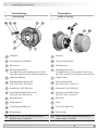
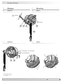
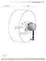
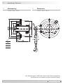
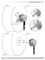
1
Gehäuse
2
Durchgehende Hohlwelle
3
Klemmring
4
Klemmringschraube:
Torx M4x12 mm bei Hohlwelle ø16+19 mm
ISO 4762, M4x16 mm bei Hohlwelle ø30 mm
5
Drehmomentblech
6
Selbstsichernde Mutter M6,
ISO 10511 (A2), SW 10 mm
7
Scheibe B6, ISO 7090 (A2)
8
Sechskantschraube M6x18 mm,
ISO 4017 (A2), SW 10 mm
9
Erdungsbolzen
10
Abdeckhaube
11
Torxschraube M4x8 mm
12
Bürstenhalter
13
Kohlebürste auch als Zubehör erhältlich:
Bestellnummer 11058991
1
Housing
2
Through hollow shaft
3
Clamping ring
4
Clamping ring screw:
Torx M4x12 mm at hollow shaft ø16+19 mm
ISO 4762, M4x16 mm at hollow shaft ø30 mm
5
Support plate
6
Self-locking nut M6,
ISO 10511 (A2), 10 mm a/f
7
Washer B6, ISO 7090 (A2)
8
Hexagon screw M6x18 mm,
ISO 4017 (A2), 10 mm a/f
9
Earth bolt
10
Cover
11
Torx screw M4x8 mm
12
Brush holder
13
Carbon brush also available as accessory:
Order number 11058991
3 Vorbereitung
3.1 Lieferumfang
3 Preparation
3.1 Scope of delivery
3 Vorbereitung / Preparation
1 9
1011
6
5
2
3 4
78
12
13

MB081T1 - 11055690
Baumer_ME11-T1_II_DE-EN (19A1)
6
Vorbereitung / Preparation 3
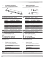
3.2 Zur Montage erforderlich
(nicht im Lieferumfang enthalten)
3.2 Required for mounting
(not included in scope of delivery)
3.3 Erforderliches Werkzeug
(nicht im Lieferumfang enthalten)
3.3 Required tools
(not included in scope of delivery)
15
14
15b 15c
15a
3x
3x
L
14
Drehmomentstütze, als Zubehör erhältlich:
Bestellnummer Länge L, Version
11043628 67...70 mm, Standard
11004078 125 (±5) mm
1)
, Standard
11002915 440 (+20/-15) mm
2)
, Standard
11054917 67...70 mm, isoliert
11072795 125 (±5) mm
1)
, isoliert
11082677 440 (+20/-15) mm
2)
, isoliert
11054918 67...70 mm, rostfrei
11072787 125 (±5) mm
1)
, rostfrei
11072737 440 (+20/-15) mm
2)
, rostfrei
15
Montageset als Zubehör erhältlich:
Bestellnummer 11071904, bestehend aus ...
15a
Gewindestange M6 (1.4104),
Länge variabel (≤210 mm)
15b
Scheibe B6,4, ISO 7090 (A2)
15c
Selbstsichernde Mutter M6,
ISO 10511 (A2), SW 10 mm
1)
Kürzbar auf ≥71 mm
2)
Kürzbar auf ≥131 mm
14
Torque arm, available as accessory:
Order number Length L, version
11043628 67...70 mm, standard
11004078 125 (±5) mm
1)
, standard
11002915 440 (+20/-15) mm
2)
, standard
11054917 67...70 mm, insulated
11072795 125 (±5) mm
1)
, insulated
11082677 440 (+20/-15) mm
2)
, insulated
11054918 67...70 mm, stainless
11072787 125 (±5) mm
1)
, stainless
11072737 440 (+20/-15) mm
2)
, stainless
15
Mounting set available as accessory:
Order number 11071904, including ...
15a
Thread rod M6 (1.4104),
length variabel (≤210 mm)
15b
Washer B6.4, ISO 7090 (A2)
15c
Self-locking nut M6,
ISO 10511 (A2), 10 mm a/f
1)
Can be shortened to ≥71 mm
2)
Can be shortened to ≥131 mm
16
Werkzeugset als Zubehör erhältlich:
Bestellnummer 11068265
16
Tool kit available as accessory:
Order number 11068265
3 mm (ø30 mm)
10 mm (2x)
TX 10 (ø16, 19 + 20 mm), TX 20
3 mm (ø30 mm)
10 mm (2x)
TX 10 (ø16, 19 + 20 mm), TX 20

4 Montage / Mounting
7
Baumer_ME11-T1_II_DE-EN (19A1)
MB081T1 - 11055690
4 Montage
4.1 Schritt 1
4 Mounting
4.1 Step 1
4.2 Schritt 2 4.2 Step 2
* Siehe Seite 5 oder 6
See page 5 or 6
7 856
* ***
14
*
3 4
* *
10 mm
10 mm
TX 10 (ø16, 19 + 20 mm)
3 mm (ø30 mm)

MB081T1 - 11055690
Baumer_ME11-T1_II_DE-EN (19A1)
8
Montage / Mounting 4
4.3 Schritt 3 4.3 Step 3
Die Antriebswelle sollte einen
möglichst kleinen Rundlauffehler
aufweisen. Rundlauffehler verursa-
chen Vibrationen, die die Lebensdauer
des Gerätes verkürzen können.
The drive shaft should have as less
runout as possible. Runouts can cause
vibrations, which can shorten the
service life of the device.
Antriebswelle einfetten. Lubricate drive shaft.
15b
15b
15c
15c 15a
15c
15b
*
*
*
* *
*
*
* Siehe Seite 6
See page 6
14
*
10 mm

4 Montage / Mounting
9
Baumer_ME11-T1_II_DE-EN (19A1)
MB081T1 - 11055690
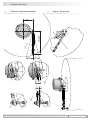
4.4 Schritt 4 - Drehmomentstütze 4.4 Step 4 - Torque arm
15°
15°
9°
9°
9°
9°
L1
L2 (≥L1)

MB081T1 - 11055690
Baumer_ME11-T1_II_DE-EN (19A1)
10
Montage / Mounting 4
4.5 Schritt 5 4.5 Step 5
Zul. Anzugsmoment:
Max. tightening torque:
M
t
= 2...3 Nm
4
3
*
*
* Siehe Seite 5
See page 5
TX 10 (ø16, 19 + 20 mm)
3 mm (ø30 mm)

11
Baumer_ME11-T1_II_DE-EN (19A1)
MB081T1 - 11055690
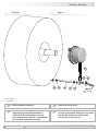
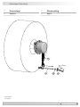
5 Abmessung / Dimension
5 Abmessung
(74208, 74210, 74211)
5 Dimension
(74208, 74210, 74211)
ød
H7
16
19
20
30
Alle Abmessungen in Millimeter (wenn nicht anders angegeben)
All dimensions in millimeters (unless otherwise stated)

MB081T1 - 11055690
Baumer_ME11-T1_II_DE-EN (19A1)
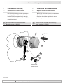
12
Betrieb und Wartung / Operation and maintenance 6
Kohlebürste
Carbon brush
6 Betrieb und Wartung
6.1 Austausch der Kohlebürsten
Bei Erreichen der minimalen Kohlebür-
stenlänge (L) von 5,3 mm sollten die
Kohlebürsten ausgewechselt werden,
damit weiterhin ein einwandfreier Betrieb
gewährleistet ist.
6 Operation and maintenance
6.1 Replace of the carbon brushes
When the minimum carbon brush length
(L) of 5.3 mm is reached , the carbon
brushes should be replaced to ensure
perfect operation.
13
*
Kohlebürste, als Zubehör erhältlich:
Bestellnummer 11058991
13
*
Carbon brush, available as accessory:
Order number 11058991
L
12
13
*
*
11
*
10
*
* Siehe Seite 5
See page 5
TX 20

13
Baumer_ME11-T1_II_DE-EN (19A1)
MB081T1 - 11055690
7 Demontage / Dismounting
7 Demontage
7.1 Schritt 1
7 Dismounting
7.1 Step 1
14
*
15a 15b 15c
* * *
* Siehe Seite 6
See page 6
10 mm

MB081T1 - 11055690
Baumer_ME11-T1_II_DE-EN (19A1)
14
Demontage / Dismounting 7
7.2 Schritt 2
7.3 Schritt 3
7.2 Step 2
7.3 Step 3
* Siehe Seite 5
See page 5
4
3
*
*
TX 10 (ø16, 19 + 20 mm)
3 mm (ø30 mm)

15
Baumer_ME11-T1_II_DE-EN (19A1)
MB081T1 - 11055690
8 Technische Daten / Technical data
8 Technische Daten
• Strombelastung:
≤1 A
≤12 A (kurzzeitig)
• Betriebsdrehzahl:
≤8500 U/min
• Betriebstemperatur:
-30...+120 °C
• Zulässige Wellenbelastung:
≤150 N axial
≤200 N radial
• Trägheitsmoment Rotor:
0,72 kgcm
2
(ø16)
0,38 kgcm
2
(ø30)
• Betriebsdrehmoment:
≤15 Ncm
• Masse ca.:
1 kg
• Schutzart DIN EN 60529:
IP55
• Wellenart:
ø16...30 mm (durchgehende Hohlwelle)
• Werkstoff:
Gehäuse: Aluminium
• Widerstandsfähigkeit:
IEC 60068-2-6
Vibration 10 g, 50-2000 Hz
IEC 60068-2-27
Schock 100 g, 6 ms
8 Technical data
• Current load:
≤1 A
≤12 A (short-term)
• Operating speed:
≤8500 rpm
• Operating temperature:
-30...+120 °C
• Admitted shaft load:
≤150 N axial
≤200 N radial
• Rotor moment of inertia:
0.72 kgcm
2
(ø16)
0.38 kgcm
2
(ø30)
• Operating torque:
≤15 Ncm
• Weight approx.:
1 kg
• Protection DIN EN 60529:
IP55
• Shaft type:
ø16...30 mm (through hollow shaft)
• Material:
Housing: aluminium
• Resistance:
IEC 60068-2-6
Vibration 10 g, 50-2000 Hz
IEC 60068-2-27
Shock 100 g, 6 ms

MB081T1 - 11055690
Baumer_ME11-T1_II_DE-EN (19A1)
16
Zubehör / Accessories 9
9 Accessories
• Torque arm size M6:
Order number see
section 4.2
• Carbon brush:
Order number 11058991
• Mounting kit for torque arm
size M6:
Order number 11071904
• Tool kit:
Order number 11068265
15
*
14
*
16
*
13
*
9 Zubehör
• Drehmomentstütze Größe M6:
Bestellnummer siehe
Abschnitt 4.2
• Kohlebürste:
Bestellnummer 11058991
• Montageset für Drehmoment-
stütze Größe M6:
Bestellnummer 11071904
• Werkzeugset:
Bestellnummer 11068265
15
*
14
*
16
*
13
*
* Siehe Abschnitt 3
See section 3

Baumer_ME11-T1_II_DE-EN (19A1-22.05.2019)
MB081T1 - 11055690
Version:
74208, 74210, 74211
Baumer Hübner GmbH
P.O. Box 12 69 43 · 10609 Berlin, Germany
Phone: +49 (0)30/69003-0 · Fax: +49 (0)30/69003-104
info@baumerhuebner.com · www.baumer.com/motion
Originalsprache der Anleitung ist Deutsch. Technische Änderungen vorbehalten.
Original language of this instruction is German. Technical modications reserved.
-
 1
1
-
 2
2
-
 3
3
-
 4
4
-
 5
5
-
 6
6
-
 7
7
-
 8
8
-
 9
9
-
 10
10
-
 11
11
-
 12
12
-
 13
13
-
 14
14
-
 15
15
-
 16
16
-
 17
17
-
 18
18
-
 19
19
-
 20
20


Baumer Motor earthing unit - ME 11 Assembly Instruction
- Typ
- Assembly Instruction
in anderen Sprachen
- English: Baumer Motor earthing unit - ME 11
Verwandte Artikel
-
Baumer Motor earthing unit ATEX/IECEx - EExME 12 Assembly Instruction
-
-
-
-
-
-
-
-
-