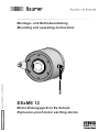
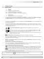
Baumer Motor earthing unit ATEX/IECEx - EExME 12 Assembly Instruction
- Typ
- Assembly Instruction

EExME 12
Motor-Erdungsgerät in Ex-Schutz
Explosion-proof motor earthing device
MB052T1 - 11080038
Baumer_EEXME12-T1_II_DE-EN (19A1)
Montage- und Betriebsanleitung
Mounting and operating instructions

Baumer_EEXME12-T1_II_DE-EN (19A1)
MB052T1 - 11080038
Inhaltsverzeichnis
Inhaltsverzeichnis
1 Allgemeine Hinweise ................................................................................................................................................ 1
2 Betrieb in explosionsgefährdeten Bereichen
.........................................................................................3
3 Sicherheitshinweise
.................................................................................................................................................5
4 Vorbereitung
..................................................................................................................................................................7
4.1 Lieferumfang
..................................................................................................................................................... 7
4.2 Zur Montage erforderlich (nicht im Lieferumfang enthalten)
...................................................8
4.3 Erforderliches Werkzeug (nicht im Lieferumfang enthalten)
...................................................9
5 Montage
.............................................................................................................................................................................9
5.1 Schritt 1
...............................................................................................................................................................9
5.2 Schritt 2
............................................................................................................................................................ 10
5.3 Schritt 3 - Drehmomentstütze
................................................................................................................11
5.4 Schritt 4
............................................................................................................................................................ 12
5.5 Schritt 5 - Option: Abdeckhaube
......................................................................................................... 12
6 Abmessung
.................................................................................................................................................................. 13
7 Betrieb und Wartung
............................................................................................................................................. 13
7.1 Austausch der Kohlebürste
.................................................................................................................... 13
8 Demontage
................................................................................................................................................................... 14
8.1 Schritt 1 - Option: Abdeckhaube
......................................................................................................... 14
8.2 Schritt 2
............................................................................................................................................................ 14
8.3 Schritt 3
............................................................................................................................................................ 15
8.4 Schritt 4
............................................................................................................................................................ 15
9 Technische Daten
.................................................................................................................................................... 16
10 Zubehör
...........................................................................................................................................................................17
11 EU-Konformitätserklärung
................................................................................................................................ 18

MB052T1 - 11080038
Baumer_EEXME12-T1_II_DE-EN (19A1)
Table of contents
Table of contents
1 General notes ................................................................................................................................................................ 2
2 Operation in potentially explosive environments
.................................................................................4
3 Security indications
.................................................................................................................................................. 6
4 Preparation
.....................................................................................................................................................................7
4.1 Scope of delivery
............................................................................................................................................ 7
4.2 Required for mounting (not included in scope of delivery)
....................................................... 8
4.3 Required tools (not included in scope of delivery)
........................................................................ 9
5 Mounting
........................................................................................................................................................................... 9
5.1 Step 1
...................................................................................................................................................................9
5.2 Step 2
................................................................................................................................................................ 10
5.3 Step 3 - Torque arm
....................................................................................................................................11
5.4 Step 4
................................................................................................................................................................ 12
5.5 Step 5 - Option: Cover
.............................................................................................................................. 12
6 Dimension
..................................................................................................................................................................... 13
7 Operation and maintenance
............................................................................................................................. 13
7.1 Replace of the carbon brush
................................................................................................................. 13
8 Dismounting
................................................................................................................................................................ 14
8.1 Step 1 - Option: Cover
.............................................................................................................................. 14
8.2 Step 2
................................................................................................................................................................ 14
8.3 Step 3
................................................................................................................................................................ 15
8.4 Step 4
................................................................................................................................................................ 15
9 Technical data
............................................................................................................................................................ 16
10 Accessories
................................................................................................................................................................. 17
11 EU Declaration of Conformity
......................................................................................................................... 18

1
Baumer_EEXME12-T1_II_DE-EN (19A1)
MB052T1 - 11080038
1 Allgemeine Hinweise
1 Allgemeine Hinweise
1.1 Zeichenerklärung:
Gefahr
Warnung bei möglichen Gefahren
Hinweis zur Beachtung
Hinweis zur Gewährleistung eines einwandfreien Betriebes des Gerätes
i
Information
Empfehlung für die Gerätehandhabung
1.2 Das Motor-Erdungsgerät in Ex-Schutz EExME 12 ist ein Gerät zur Ableitung von parasi-
tären Wellenströmen, das mit Sorgfalt nur von technisch qualiziertem Per sonal gehandhabt
werden darf.
1.3 Die zu erwartende Lebensdauer des Gerätes hängt von den Kugellagern ab, die mit einer
Dauerschmierung ausgestattet sind.
1.4 Kohlebürsten haben eine zu erwartende Lebensdauer, die vom Stromdurchgang abhängt
und in der Regel der Kugellagerlebensdauer entspricht. Ein Wechsel der Kohlebürsten ist nur
vorsorglich erforderlich.
1.5
Der Lagertemperaturbereich des Gerätes liegt zwischen -15 °C bis +70 °C.
1.6
Der maximale Umgebungstemperaturbereich für den Einsatz des Gerätes im
Ex-Bereich beträgt -55 °C bis +50 °C bei T5 und -55 °C bis +60 °C bei T4.
Externe Wärmequellen, wie z. Bsp. Anbauten, dürfen den maximalen Umge-
bungstemperaturbereich nicht überschreiten.
1.7
EU-Konformitätserklärung gemäß den europäischen Richtlinien.
1.8 Wir gewähren 2 Jahre Gewährleistung im Rahmen der Bedingungen des Zentralverbandes der
Elektroindustrie (ZVEI).
1.9 Reparaturen oder Wartungsarbeiten sind ausschließlich vom Hersteller durchzuführen. Am
Gerät dürfen keine Veränderungen vorgenommen werden.
Bei Zuwiderhandlung erlischt die Ex-Zulassung.
1.10 Bei Rückfragen bzw. Nachlieferungen sind die auf dem Typenschild des Gerätes angege-
benen Daten, insbesondere Typ und Seriennummer, unbedingt anzugeben.
1.11
Entsorgung (Umweltschutz):
Gebrauchte Elektro- und Elektronikgeräte dürfen nicht im Hausmüll entsorgt werden.
Das Produkt enthält wertvolle Rohstoffe, die recycelt werden können. Wenn immer
möglich sollen Altgeräte lokal am entsprechenden Sammeldepot entsorgt werden. Im
Bedarfsfall gibt Baumer den Kunden die Möglichkeit, Baumer-Produkte fachgerecht zu entsor-
gen. Weitere Informationen siehe www.baumer.com.
i
Achtung!
Beschädigung des auf dem Gerät bendlichen Siegels führt zu Gewährleistungsver-
lust.

MB052T1 - 11080038
Baumer_EEXME12-T1_II_DE-EN (19A1)
2
General notes 1
1 General notes
1.1 Symbol guide:
Danger
Warnings of possible danger
General information for attention
Informations to ensure correct device operation
i
Information
Recommendation for device handling
1.2 The explosion-proof motor earthing device EExME 12 is a device for leakage of paraseti-
cal shaft currents which must be handled with care by skilled personnel only.
1.3 The expected service life of the device depends on the ball bearings, which are equipped with
a permanent lubrication.
1.4 The expected service life of carbon brushes depends on the electrical current and is usually
consistent with the service life of the ball bearings. Replacement of the carbon brushes is only a
recommended precaution.
1.5
The storage temperature range of the device is between -15 °C and +70 °C.
1.6
In Ex areas the device must only be used within the ambient temperature range
from -55 °C to +50 °C for T5 and -55 °C to +60 °C for T4.
External heat sources such as attached installations must not exceed the maximum
ambient temperature range.
1.7
EU Declaration of Conformity meeting to the European Directives.
1.8 We grant a 2-year warranty in accordance with the regulations of the ZVEI (Central Association
of the German Electrical Industry).
1.9 Repair or maintenance work must be carried out by the manufacturer. Alterations of the de-
vice are not permitted.
Contravention invalidates the EX approval.
1.10 In the event of queries or subsequent deliveries, the data on the device type label must be
quoted, especially the type designation and the serial number.
1.11
Disposal (environmental protection):
Do not dispose of electrical and electronic equipment in household waste. The product
contains valuable raw materials for recycling. Whenever possible, waste electrical and
electronic equipment should be disposed locally at the authorized collection point. If
necessary, Baumer gives customers the opportunity to dispose of Baumer products profession-
ally. For further information see www.baumer.com.
i
Warning!
Damaging the seal on the device invalidates warranty.

3
Baumer_EEXME12-T1_II_DE-EN (19A1)
MB052T1 - 11080038
2 Betrieb in explosionsgefährdeten Bereichen
2 Betrieb in explosionsgefährdeten Bereichen
2.1 Das Gerät entspricht den Anforderungen der Richtlinie 2014/34/EU für explosionsgefährdete
Bereiche sowie dem IECEx-Scheme.
Der Einsatz ist gemäß der Gerätekategorie 2 G (Ex-Atmosphäre Gas) zulässig.
Ex-Kennzeichnung: II 2 G Ex db IIC T4/T5 Gb
Ex db IIC T4/T5 Gb
Normenkonformität: EN 60079-0:2012 + A11:2013
IEC 60079-0:2011 (Ed.6)
Allgemeine Bestimmungen
EN 60079-1:2014
IEC 60079-1:2014 (Ed.7)
Druckfeste Kapselung „d“
Zündschutzart: db
Temperaturklasse: T4/T5
Gerätegruppe: II
Explosionsgruppe: IIC
Geräteschutzniveau: Gb
Der Einsatz in anderen explosionsgefährdeten Bereichen ist nicht zulässig.
EU-Baumusterprüfbescheinigung auf Anfrage:
TÜV NORD CERT Nr. TÜV 02 ATEX 1920 X / IECEx TUN 11.0036X
2.2 Besondere Bedingung:
Der maximale Umgebungstemperaturbereich für den Einsatz des Gerätes im Ex-Bereich
beträgt -55 °C bis +50 °C bei T5 und -55 °C bis +60 °C bei T4.
2.3 Eine gegebenenfalls in der sonstigen technischen Dokumentation aufgeführte UL-Listung gilt
nicht für den Einsatz im Ex-Bereich.
2.4 Das Gerät darf nur in Betrieb genommen werden, wenn ...
– die Angaben auf dem Typenschild des Gerätes mit dem zulässigen Ex-Einsatzbereich vor
Ort übereinstimmen (Gerätegruppe, Kategorie, Zone, Temperaturklasse bzw. maximale
Oberächentemperatur),
– das Gerät unbeschädigt ist (keine Schäden durch Transport und Lagerung) und
– sichergestellt ist, dass keine explosionsfähige Atmosphäre, Öle, Säure, Gase, Dämpfe,
Strahlungen etc. bei der Montage vorhanden sind.
2.5 An Betriebsmittel, die in explosionsgefährdeten Bereichen eingesetzt werden, darf keine Ver-
änderung vorgenommen werden. Reparaturen an explosionsgeschützten Betriebsmittel dürfen
ausschließlich vom Hersteller durchgeführt werden.
Bei Zuwiderhandlung erlischt die Ex-Zulassung.
2.6 Bei der Montage und Inbetriebnahme ist die Norm EN 60079-14 / IEC 60079-14 zu beachten.
Das Gerät ist entsprechend den Angaben in der Montage- und Betriebsanleitung zu
betreiben. Die für die Verwendung bzw. den geplanten Einsatzzweck zutreffenden
Gesetze, Richtlinien und Normen sind zu beachten.

MB052T1 - 11080038
Baumer_EEXME12-T1_II_DE-EN (19A1)
4
Operation in potentially explosive environments 2
2 Operation in potentially explosive environments
2.1 The device complies with the directive 2014/34/EU for potentionally explosive atmospheres
and with the IECEx Scheme.
It can be used in accordance with equipment category 2 G (explosive gas atmosphere).
Ex labeling: II 2 G Ex db IIC T4/T5 Gb
Ex db IIC T4/T5 Gb
Conforms to standard: EN 60079-0:2012 + A11:2013
IEC 60079-0:2011 (Ed.6)
Generaldenation
EN 60079-1:2014
IEC 60079-1:2014 (Ed.7)
Explosion proof enclosure „d“
Type of protection: db
Temperature class: T4/T5
Group of equipment: II
Explosive gas group: IIC
Device protection level: Gb
The operation in other explosive atmospheres is not permissible.
EUtypeexaminationcerticateondemand:
TÜV NORD CERT Nr. TÜV 02 ATEX 1920 X / IECEx TUN 11.0036X
2.2 Special condition:
In Ex areas the device must only be used within the ambient temperature range from -55 °C to
+50 °C for T5 and -55 °C to +60 °C for T4.
2.3 An UL listing that may be stated elsewhere is not valid for use in explosive environments.
2.4 Operation of the device is only permissible when ...
– the details on the type label of the device match the on-site conditions for the permissible
Ex area in use (group of equipment, equipment category, zone, temperature class or maxi-
mum surface temperature),
– the device is undamaged (no damage resulting from transport or storage), and
– it has been checked that there is no explosive atmosphere, oils, acids, gases, vapors,
radiation etc. present when mounting.
2.5 It is not permissible to make any alteration to equipment that is used in potentially explosive en-
vironments. Repairs of explosion-protected equipment may only be carried out by the manufac-
turer.
Contravention invalidates the EX approval.
2.6 Attend the norm EN 60079-14 / IEC 60079-14 during mount and operation.
The device must be operated in accordance with the stipulations of the mounting and
operating instructions. The relevant laws, regulations and standards for the planned
application must be observed.

5
Baumer_EEXME12-T1_II_DE-EN (19A1)
MB052T1 - 11080038
3 Sicherheitshinweise
3 Sicherheitshinweise
3.1 Verletzungsgefahr durch rotierende Wellen
Haare und Kleidungsstücke können von rotierenden Wellen erfasst werden.
• Vor allen Arbeiten alle Betriebsspannungen ausschalten und Maschinen stillsetzen.
3.2 Zerstörungsgefahr durch mechanische Überlastung
Eine starre Befestigung kann zu Überlastung durch Zwangskräfte führen.
• Die Beweglichkeit des Gerätes niemals einschränken.
Unbedingt die Montagehinweise beachten.
• Die vorgegebenen Abstände und/oder Winkel unbedingt einhalten.
3.3 Zerstörungsgefahr durch mechanischen Schock
Starke Erschütterungen, z. B. Hammerschläge, können zur Zerstörung des Gerätes führen.
• Niemals Gewalt anwenden.
Bei sachgemäßer Montage lässt sich alles leichtgängig zusammenfügen.
• Für die Demontage geeignetes Abziehwerkzeug benutzen.
3.4 Zerstörungsgefahr durch Verschmutzung
Schmutz kann im Gerät zur Beschädigung führen.
• Während aller Arbeiten am Gerät auf absolute Sauberkeit achten.
• Niemals Öl oder Fett in das Innere des Gerätes gelangen lassen.
3.5 Zerstörungsgefahr durch klebende Flüssigkeiten
Klebende Flüssigkeiten können die Kugellager beschädigen. Die Demontage eines mit der Ach-
se verklebten Gerätes kann zu dessen Zerstörung führen.
3.6 Explosionsgefahr
Das Gerät darf in explosiongefährdeten Bereichen der Gerätekategorie 2 G (Zone 1) eingesetzt
werden. Der Betrieb in anderen explosionsgefährdeten Bereichen ist nicht zulässig.

MB052T1 - 11080038
Baumer_EEXME12-T1_II_DE-EN (19A1)
6
Security indications 3
3 Security indications
3.1 Risk of injury due to rotating shafts
Hair and clothes may become tangled in rotating shafts.
• Before all work switch off all voltage supplies and ensure machinery is stationary.
3.2 Risk of destruction due to mechanical overload
Rigid mounting may give rise to constraining forces.
• Never restrict the freedom of movement of the device.
The mounting instructions must be followed.
• Itisessentialthatthespeciedclearancesand/oranglesareobserved.
3.3 Risk of destruction due to mechanical shock
Violent shocks, e. g. due to hammer impacts, can lead to the destruction of the device.
• Never use force.
Mounting is simple when correct procedure is followed.
• Use suitable puller for dismounting.
3.4 Risk of destruction due to contamination
Dirt penetrating inside the device can damage the unit.
• Absolute cleanliness must be maintained when carrying out any work at the device.
• Never allow lubricants to penetrate the device.
3.5 Risk of destruction due to adhesive uids
Adhesiveuidscandamagetheballbearings.Dismountingadevice,securedtoashaftby
adhesive may lead to the destruction of the device.
3.6 Explosion risk
You can use the device in areas with explosive atmospheres of equipment category 2 G (Zone
1). The operation in other explosive atmospheres is not permissible.

7
Baumer_EEXME12-T1_II_DE-EN (19A1)
MB052T1 - 11080038
1
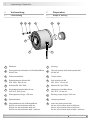
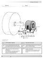
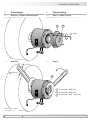
Gehäuse
2
Durchgehende Hohlwelle mit Schlüsseläche
SW 45 mm
3
Drehmomentblech
4
Selbstsichernde Mutter M6,
ISO 10511, SW 10 mm
5
Scheibe B6, ISO 7090
6
Sechskantschraube M6x18 mm,
ISO 4017, SW 10 mm
7
Erdungsband, Länge ~230 mm
8
Spannelement
9
Gewindebuchse mit Schlüsseläche
SW 36 mm bei Hohlwelle ø20 mm,
SW 46 mm bei Hohlwelle ø30 mm,
SW 50 mm bei Hohlwelle ø40 + ø42 mm
1
Housing
2
Throughhollowshaftwithspannerat
45 mm a/f
3
Torque sheet
4
Self-locking nut M6,
ISO 10511, 10 mm a/f
5
Washer B6, ISO 7090
6
Hexagon screw M6x18 mm,
ISO 4017, 10 mm a/f
7
Earthing strap, length ~230 mm
8
Clamping element
9
Insertnutwithspannerat
36 mm a/f at hollow shaft of ø20 mm,
46 mm a/f at hollow shaft of ø30 mm,
50 mm a/f at hollow shaft of ø40 + ø42 mm
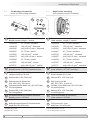
4 Vorbereitung
4.1 Lieferumfang
4 Preparation
4.1 Scope of delivery
4 Vorbereitung / Preparation
145
3
6 8 9
72

MB052T1 - 11080038
Baumer_EEXME12-T1_II_DE-EN (19A1)
8
Vorbereitung / Preparation 4
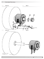
10
11
11b
11a
11d11e
11c
12a
12b
3x
3x
4x
4.2 Zur Montage erforderlich
(nicht im Lieferumfang enthalten)
4.2 Required for mounting
(not included in scope of delivery)
L
10
Drehmomentstütze, als Zubehör erhältlich:
Bestellnummer Länge L, Version
11043628 67...70 mm, Standard
11004078 125 (±5) mm
1)
, Standard
11002915 440 (+20/-15) mm
2)
, Standard
11054917 67...70 mm, isoliert
11072795 125 (±5) mm
1)
, isoliert
11082677 440 (+20/-15) mm
2)
, isoliert
11054918 67...70 mm, rostfrei
11072787 125 (±5) mm
1)
, rostfrei
11072737 440 (+20/-15) mm
2)
, rostfrei
11
Montageset als Zubehör erhältlich:
Bestellnummer 11077197, bestehend aus ...
11a
Gewindestange M6 (1.4104),
Länge variabel (≤210 mm)
11b
Scheibe B6,4, ISO 7090 (A2)
11c
Selbstsichernde Mutter M6,
ISO 10511 (A2), SW 10 mm
11d
Zylinderschraube M6x8 mm, ISO 1207 (Ms)
für Erdungsband
11e
Scheibe B6,4, ISO 7090 (Ms)
für Erdungsband
12
Set Abdeckhaube als Zubehör erhältlich:
Bestellnummer 11075445
12a
Abdeckhaube
12b
Befestigungsschraube für Abdeckhaube
M4x8 mm, ISO 4762 (A2)
1)
Kürzbar auf ≥71 mm
2)
Kürzbar auf ≥131 mm
10
Torque arm, available as accessory:
Order number Length L, version
11043628 67...70 mm, standard
11004078 125 (±5) mm
1)
, standard
11002915 440 (+20/-15) mm
2)
, standard
11054917 67...70 mm, insulated
11072795 125 (±5) mm
1)
, insulated
11082677 440 (+20/-15) mm
2)
, insulated
11054918 67...70 mm, stainless
11072787 125 (±5) mm
1)
, stainless
11072737 440 (+20/-15) mm
2)
, stainless
11
Mounting kit available as accessory:
Order number 11077197, including ...
11a
Thread rod M6 (1.4104),
lengthvariabel(≤210mm)
11b
Washer B6.4, ISO 7090 (A2)
11c
Self-locking nut M6,
ISO 10511 (A2), 10 mm a/f
11d
Cylinder screw M6x8 mm, ISO 1207 (Ms)
for earthing strap
11e
Washer B6.4, ISO 7090 (Ms)
for earthing strap
12
Cover kit available as accessory:
Order number 11075445
12a
Cover
12b
Fixing screw for cover
M4x8 mm, ISO 4762 (A2)
1)
Canbeshortenedto≥71mm
2)
Canbeshortenedto≥131mm
12

9
Baumer_EEXME12-T1_II_DE-EN (19A1)
MB052T1 - 11080038
4-5 Vorbereitung - Montage / Preparation - Mounting
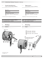
5 Montage
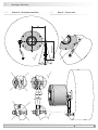
5.1 Schritt 1
5 Mounting
5.1 Step 1
6
*
534
8 9
***
* *
10
*
* Siehe Seite 7 oder 8
See page 7 or 8
4.3 Erforderliches Werkzeug
(nicht im Lieferumfang enthalten)
4.3 Required tools
(not included in scope of delivery)
10 mm
10 mm
36 mm (øA = ø20 mm)
46 mm (øA = ø30 mm)
50 mm (øA = ø40 + ø42 mm)
13
Werkzeugset als Zubehör erhältlich:
Bestellnummer 11068265
13
Tool kit available as accessory:
Order number 11068265
3 mm
1,6x8 mm
10 mm (2x), 45 mm
36 mm
3)
, 46 mm
3)
oder 50 mm
3)
3)
Je nach Version der durchgehenden Hohlwelle
3 mm
1.6x8 mm
10 mm (2x), 45 mm
36 mm
3)
, 46 mm
3)
or 50 mm
3)
3)
Depending on the version of the trough hollow shaft
øA
Durchgehende Hohlwelle
Through hollow shaft

MB052T1 - 11080038
Baumer_EEXME12-T1_II_DE-EN (19A1)
10
Montage / Mounting 5
5.2 Schritt 2 5.2 Step 2
11b
11b11c
11c
11e 11d
11a
7
11c11b
10
*
**
*
* *
* *
** *
10 mm
1.6x8 mm
Vor der Inbetriebnahme muss das
Erdungband angeschlossen werden.
The earthing strap must be connected
before commissioning.
Die Antriebswelle sollte einen
möglichst kleinen Rundlauffehler
aufweisen.
Rundlauffehler verursachen Vibrati-
onen, die die Lebensdauer des
Gerätes verkürzen können.
The drive shaft should have as less
runout as possible.
Runouts can cause vibrations, which
can shorten the service life of the
device.
Antriebswelle einfetten. Lubricate drive shaft.
* Siehe Seite 7 oder 8
See page 7 or 8

5 Montage / Mounting
11
Baumer_EEXME12-T1_II_DE-EN (19A1)
MB052T1 - 11080038
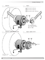
5.3 Schritt 3 - Drehmomentstütze 5.3 Step 3 - Torque arm
15°
15°
9°
9°
9°
9°
L1
L2 (≥L1)

MB052T1 - 11080038
Baumer_EEXME12-T1_II_DE-EN (19A1)
12
Montage / Mounting 5
5.4 Schritt 4 5.4 Step 4
5.5 Schritt 5 - Option: Abdeckhaube 5.5 Step 5 - Option: Cover
Zul. Anzugsmoment:
Max. tightening torque:
M
t
= 2...3 Nm
8 9
* *
13a 13b
* *
* Siehe Seite 7 oder 8
See page 7 or 8
36 mm (øA = ø20 mm)
46 mm (øA = ø30 mm)
50 mm (øA = ø40 + ø42 mm)
45 mm
3 mm
øA

13
Baumer_EEXME12-T1_II_DE-EN (19A1)
MB052T1 - 11080038
L
ø
ø
6-7 Abmessung - Betrieb und Wartung / Dimension - Operation and maintenance
7 Betrieb und Wartung
7.1 Austausch der Kohlebürste
Bei Erreichen der minimalen Kohle-
bürstenlänge (L) von 5,3 mm sollte die
Kohlebürste ausgewechselt werden,
damit weiterhin ein einwandfreier Betrieb
gewährleistet ist.
7 Operation and maintenance
7.1 Replace of the carbon brush
When the minimum carbon brush length
(L) of 5.3 mm is reached, the carbon
brush should be replaced to ensure per-
fect operation.
Verlust der Ex-Zulassung bei Öffnen
des Gerätes!
Die Kohlebürste darf nur vom Hersteller
ausgetauscht werden, da ansonsten die
Ex-Zulassung nicht mehr gewährleistet
wird.
Forfeiture of the Ex protection when
opening the device!
Replace of the carbon brush must be
carried out by the manufacturer otherwise
you lost the warranty for the Ex protection
of the device.
6 Abmessung
(74200)
6 Dimension
(74200)
Zubehör
Accessory
45 mm
Alle Abmessungen in Millimeter (wenn nicht anders angegeben)
All dimensions in millimeters (unless otherwise stated)
ød
H7
d1 d2 L
20 M32
36
6
30 M45
46
7
40 M46
50
7
42 M48
50
7
Kohlebürste als Zubehör erhältlich:
Bestellnummer 11058991
Carbon brush, available as accessory:
Oder number 11058991
L
Kohlebürste
Carbon brush

MB052T1 - 11080038
Baumer_EEXME12-T1_II_DE-EN (19A1)
14
Demontage / Dismounting 8
8.2 Schritt 2 8.2 Step 2
8 Demontage
8.1 Schritt 1 - Option: Abdeckhaube
8 Dismounting
8.1 Step 1 - Option: Cover
13a 13b
* *
9
*
* Siehe Seite 7 oder 8
See page 7 or 8
45 mm
36 mm (øA = ø20 mm)
46 mm (øA = ø30 mm)
50 mm (øA = ø40 + ø42 mm)
øA
3 mm

15
Baumer_EEXME12-T1_II_DE-EN (19A1)
MB052T1 - 11080038
8 Demontage / Dismounting
8.3 Schritt 3 8.3 Step 3
8.4 Schritt 4 8.4 Step 4
* Siehe Seite 7 oder 8
See page 7 or 8
8 9
* *
11c11b11a
10
***
*
10 mm
11d
11e
7
*
*
*
1.6x8 mm

MB052T1 - 11080038
Baumer_EEXME12-T1_II_DE-EN (19A1)
16
Technische Daten / Technical data 9
9 Technische Daten
• Strombelastung:
≤1 A
≤12 A (kurzzeitig, nicht in explosionsge-
fährdeten Bereichen)
• Betriebsdrehzahl:
≤8500 U/min
• Umgebungstemperatur:
-55...+50 °C (T5)
-55...+60 °C (T4)
• Zulässige Wellenbelastung:
≤150 N axial
≤200 N radial
• Trägheitsmoment Rotor:
3,7 kgcm
2
• Betriebsdrehmoment:
≤15 Ncm
• Explosionsschutz:
II 2 G Ex db IIC T4/T5 Gb
Ex db IIC T4/T5 Gb
• Masse ca.:
3,5 kg
• Schutzart DIN EN 60529:
IP56
• Wellenart:
ø20...42 mm (durchgehende Hohlwelle)
• Werkstoff:
Gehäuse: Aluminium
• Widerstandsfähigkeit:
IEC 60068-2-6
Vibration 10 g, 50-2000 Hz
IEC 60068-2-27
Schock 100 g, 6 ms
• Zulassung:
CE
9 Technical data
• Current load:
≤1A
≤12A(short-term,notininpotentially
explosive atmospheres)
• Operating speed:
≤8500rpm
• Ambient temperature:
-55...+50 °C (T5)
-55...+60 °C (T4)
• Admitted shaft load:
≤150Naxial
≤200Nradial
• Rotor moment of inertia:
3.7 kgcm
2
• Operating torque:
≤15Ncm
• Explosion protection:
II 2 G Ex db IIC T4/T5 Gb
Ex db IIC T4/T5 Gb
• Weight approx.:
3.5 kg
• Protection DIN EN 60529:
IP56
• Shaft type:
ø20...42 mm (through hollow shaft)
• Material:
Housing: aluminium
• Resistance:
IEC 60068-2-6
Vibration 10 g, 50-2000 Hz
IEC 60068-2-27
Shock 100 g, 6 ms
• Approval:
CE

17
Baumer_EEXME12-T1_II_DE-EN (19A1)
MB052T1 - 11080038
10 Zubehör / Accessories
10 Accessories
• Torque arm size M6:
Order number see
section 4.2
• Mounting kit for torque arm
size M6 and earthing strap:
Order number 11077197
• Cover kit:
Order number 11075445
• Carbon brush:
Order number 11058991
! Mind section 7 !
• Tool kit:
Order number 11068265
10 Zubehör
• Drehmomentstütze Größe M6:
Bestellnummer siehe
Abschnitt 4.2
• Montageset für Drehmomentstüt-
ze Größe M6 und Erdungsband:
Bestellnummer 11077197
• Set Abdeckhaube:
Bestellnummer 11075445
• Kohlebürste:
Bestellnummer 11058991
! Abschnitt 7 beachten !
• Werkzeugset:
Bestellnummer 11068265
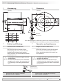
13
*
13
*
10
*
10
*
11
*
12
*
11
*
12
*
* Siehe Abschnitt 4
See section 4
Seite wird geladen ...
Seite wird geladen ...
Seite wird geladen ...
Seite wird geladen ...
-
 1
1
-
 2
2
-
 3
3
-
 4
4
-
 5
5
-
 6
6
-
 7
7
-
 8
8
-
 9
9
-
 10
10
-
 11
11
-
 12
12
-
 13
13
-
 14
14
-
 15
15
-
 16
16
-
 17
17
-
 18
18
-
 19
19
-
 20
20
-
 21
21
-
 22
22
-
 23
23
-
 24
24


Baumer Motor earthing unit ATEX/IECEx - EExME 12 Assembly Instruction
- Typ
- Assembly Instruction
in anderen Sprachen
Verwandte Artikel
-
Baumer Motor earthing unit ATEX/IECEx - EExME 12 C Assembly Instruction
-
-
-
-
Baumer Motor earthing unit - ME 11 Assembly Instruction
-
-
-
-
-