
EB-RV283P = B
RV283P
Einbau-Anleitung • Installation Instructions • Instructions de montage
Инструкция по установке
Rückflussverhinderer
Non Return Valve
Clapet antiretour
Обратный клапан
4
16
0
5
10
15
bar
16
0
5
10
15
bar
❷
❶
1
2
3

32
1. Installation
It is necessary during installation to observe
codes of good practice, to comply with local
requirements and to follow the installation
instructions. The installation location should
be protected against frost and be easily
accessible.
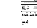
1.1 Assembly (Fig. 1)
1. Flush pipework thoroughly.
2. Close valves 1 and 2 .
3. Install the non return valve 3 .
● Install in horizontal or with flow
direction pointing upwards in vertical
pipework
● Test valve 4 pointing downwards
4. Slowly open valves 1 and 2 .
2. Maintenance (Fig. 2)
Planned maintenance is recommended and
DIN 1988, Part 8 specifies the following
operations:
The check valve must be tested once a
year. This can be done by the user.
1. Close shutoff valve 1 .
2. Open the test valve 4 .
Until the pressure has been relieved, a
little water will emit from the test valve.
Emission of water should stop after a
few moments. If water continues to drip
or run without stopping, then the check
valve is either damaged or dirty. This
should be corrected by a specialist.
3. Close test valve 4 .
4. Open shutoff valve 1 .
3. Range of Application
Versions
A = Drilled flange, PN 16 to DIN 2533,
DN 40-300, NBR seals
B = Drilled flange, PN 10, DIN 2532,
DN 200-300, NBR seals
GB
ZA = Drilled flange, PN 16, DIN 2533,
DN 40-300, EPDM seals
ZB =Drilled flange, PN 10, DIN 2532,
DN 200-300, EPDM seals
for versions A and ZA
Operating pressure max. 16 bar
Opening pressure approx. 0,05 bar
Operating temperature
Water up to 90 °C, compressed air and
other mediums up to 70 °C
Medium
Water, compressed air and light
heating oils deirved from crude oil,
pure animal and vegetable oils,
kerosene, petrol with aromatic content
less than 15%
for versions B and ZB
Operating pressure max. 10 bar
Opening pressure approx. 0,05 bar
Operating max.140 °C
temperature
Medium
Hot water and saturated steam,
Ketones, glycol-based hydraulic and
brake fluids, washing suds
4. Safety Guidelines
1.Use the appliance
● In good condition
● According to regulations
● With due regard to safety
2.Follow installation instructions
3.Immediately rectify any malfunctions
which may influence safety.
4.RV283P non return valve is exclusively
for use in applications detailed in these
installation instructions.
Any variation from this or other use will
not comply with requirements.
ZA = Flansche gebohrt, PN 16, DIN 2533,
DN 40-300, Lippendichtung aus EPDM
ZB =Flansche gebohrt, PN 10, DIN 2532,
DN200-300, Lippendichtung aus EPDM
für Variante A und ZA
Betriebsdruck max. 16 bar
Öffnungsdruck ca. 0,05 bar
Betriebstemperatur
Wasser bis 90 °C Druckluft und andere
Medien bis 70 °C
Medium
Wasser, Druckluft, mittlere und leichte
Heizöle auf Erdölbasis, rein tierische
und pflanzliche Öle, Kerrosin, Benzin
mit Aromatenanteil unter 15%
für Variante B und ZB
Betriebsdruck max. 10 bar
Öffnungsdruck ca. 0,05 bar
Betriebstemperatur max. 140 °C
Medium
Heißwasser und Sattdampf, Ketonen,
Hydraulik- und Bremsflüssigkeiten
auf Glykolbasis und Waschlaugen
4. Sicherheitshinweise
1.Benutzen Sie das Gerät
● in einwandfreiem Zustand
● bestimmungsgemäß
● sicherheits- und gefahrenbewusst.
2.Beachten Sie die Einbau-Anleitung.
3.Lassen Sie Störungen, welche die
Sicherheit beeinträchtigen können,
umgehend beseitigen.
4.Der Rückflussverhinderer RV283P ist
ausschließlich für die in dieser Einbau-
Anleitung genannten Einsatzgebiete
bestimmt. Eine andere oder darüber
hinausgehende Benutzung gilt als
nicht bestimmungsgemäß.
1. Einbau
Beim Einbau sind die örtlichen Vorschriften,
sowie allgemeine Richtlinien und die Einbau-
Anleitung zu beachten. Der Einbauort muss
frostsicher und gut zugänglich sein.
1.1 Montage (Abb. 1)
1. Rohrleitung gut durchspülen.
2. Ventil 1 und 2 schließen.
3. Rückflussverhinderer 3 einbauen
● Einbaulage in waagrechte oder in Fließ-
richtung nach oben führende Rohrleitung
● Prüfstopfen 4 nach unten.
4. Ventil 1 und 2 langsam öffnen.
2. Instandhaltung (Abb. 2)
☞ Wir empfehlen dem Betreiber, einen
Wartungsvertrag mit einem Instal-
lationsunternehmen abzuschließen.
Entsprechend der DIN 1988, Teil 8 sind
folgende Maßnahmen regelmäßig durchzu-
führen:
Der Rückflussverhinderer muss jährlich
überprüft werden. Diese Überprüfung darf
vom Betreiber durchgeführt werden.
1. Absperrventil 1 schließen.
2. Prüfstopfen 4 öffnen.
Bis zur Druckentlastung wird etwas
Wasser am Prüfstopfen ausfließen.
Nach kurzer Zeit muss der Wasseraus-
fluss aufhören. Tropft oder läuft das
Wasser beständig weiter, so ist der
Rückflussverhinderer beschädigt oder
verschmutzt. Wenden Sie sich zur
Fehlerbeseitigung an Ihren Installateur.
3. Prüfstopfen 4 wieder schließen.
4. Absperrventil 1 wieder öffnen.
3. Verwendungsbereich
Varianten
A = Flansche gebohrt, PN 16, DIN 2533,
DN 40-300, Lippendichtung aus NBR
B = Flansche gebohrt, PN 10, DIN 2532,
DN 200-300, Lippendichtung aus NBR
D
Seite wird geladen ...

76
①
④
③
②
⑤
⑥
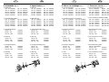
5. Pièces de rechange (Fig. 5)
① Cône de fermeture
DN 40 5605800 DN 50 5605900
DN 65 0900376 DN 80 0900377
DN 100 0900378 DN 125 0900379
DN 150 0900380 DN 200 0900381
DN 250 0900382 DN 300 0900383
② Fermeture à lèvres (en Perbinan)
DN 40 2238700 DN 50 2238800
DN 65 5350000 DN 80 5350300
DN 100 5350400 DN 125 2070300
DN 150 2067300 DN 200 2238900
DN 250 2239000 DN 300 2239100
③ Bouchon hexagonal
DN 40 - 50 5726800
DN 65 - 100 2248700
DN 125 - 300 2591000
④ Joint
DN 40 - 50 2166600
DN 65 - 100 5350500
DN 125 - 300 2698000
⑤ Bouchon hexagonal
DN 40 - 50 2248600
DN 65 - 100 2248700
DN 125 - 300 2591000
⑥ Joint
DN 40 - 50 2221200
DN 65 - 100 5350500
DN 125 - 300 2698000
5. Запасные части (Рис. 5)
① Уплотнительный затвор
DN 40 5605800 DN 50 5605900
DN 65 0900376 DN 80 0900377
DN 100 0900378 DN 125 0900379
DN 150 0900380 DN 200 0900381
DN 250 0900382 DN 300 0900383
② Уплотнительная манже т а (NRB)
DN 40 2238700 DN 50 2238800
DN 65 5350000 DN 80 5350300
DN 100 5350400 DN 125 2070300
DN 150 2067300 DN 200 2238900
DN 250 2239000 DN 300 2239100
③ Шестигранная пробка
DN 40 - 50 5726800
DN 65 - 100 2248700
DN 125 - 300 2591000
④ Уплотнительное кольцо
DN 40 - 50 2166600
DN 65 - 100 5350500
DN 125 - 300 2698000
⑤ Шестигранная пробка
DN 40 - 50 2248600
DN 65 - 100 2248700
DN 125 - 300 2591000
⑥ Уплотнительное кольцо
DN 40 - 50 2221200
DN 65 - 100 5350500
DN 125 - 300 2698000
F RUS
5. Spare Parts (Fig. 5)
① Seal disc
DN 40 5605800 DN 50 5605900
DN 65 0900376 DN 80 0900377
DN 100 0900378 DN 125 0900379
DN 150 0900380 DN 200 0900381
DN 250 0900382 DN 300 0900383
② NBR seal ring
DN 40 2238700 DN 50 2238800
DN 65 5350000 DN 80 5350300
DN 100 5350400 DN 125 2070300
DN 150 2067300 DN 200 2238900
DN 250 2239000 DN 300 2239100
③ Hexagonal blanking plug
DN 40 - 50 5726800
DN 65 - 100 2248700
DN 125 - 300 2591000
④ Seal ring
DN 40 - 50 2166600
DN 65 - 100 5350500
DN 125 - 300 2698000
⑤ Hexagonal blanking plug
DN 40 - 50 2248600
DN 65 - 100 2248700
DN 125 - 300 2591000
⑥ Seal ring
DN 40 - 50 2221200
DN 65 - 100 5350500
DN 125 - 300 2698000
5. Ersatzteile (Abb. 5)
① Dichtkegel
DN 40 5605800 DN 50 5605900
DN 65 0900376 DN 80 0900377
DN 100 0900378 DN 125 0900379
DN 150 0900380 DN 200 0900381
DN 250 0900382 DN 300 0900383
② Lippendichtring (NBR)
DN 40 2238700 DN 50 2238800
DN 65 5350000 DN 80 5350300
DN 100 5350400 DN 125 2070300
DN 150 2067300 DN 200 2238900
DN 250 2239000 DN 300 2239100
③ Sechskant-Stopfen
DN 40 - 50 5726800
DN 65 - 100 2248700
DN 125 - 300 2591000
④ Dichtring
DN 40 - 50 2166600
DN 65 - 100 5350500
DN 125 - 300 2698000
⑤ Sechskant-Stopfen
DN 40 - 50 2248600
DN 65 - 100 2248700
DN 125 - 300 2591000
⑥ Dichtring
DN 40 - 50 2221200
DN 65 - 100 5350500
DN 125 - 300 2698000
GBD
①
④
③
②
⑤
⑥

MU1H-1203GE23 R0603
Automation and Control Products
Honeywell AG Phone: (49) 6261 810
Hardhofweg Fax: (49) 6261 81309 www.honeywell.de/haustechnik
-
 1
1
-
 2
2
-
 3
3
-
 4
4
-
 5
5


in anderen Sprachen
- English: Honeywell RV283P Owner's manual
- français: Honeywell RV283P Le manuel du propriétaire
- русский: Honeywell RV283P Инструкция по применению