
EB-RV280=A
MU1H-1201GE23 R0602
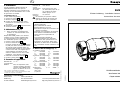
RV280
Einbau-Anleitung
.
Installation Instructions
Instructions de montage
Rückflussverhinderer
Non Return Valve
Clapet antiretour
F
1. Installation
Lors du montage il faudra observer la
réglementation locale ainsi que les
directives générales et les instructions de
montage. Le lieu d’installation sera à l’abri
du gel et bien accessible.
1.1 Montage (Fig. 5)
1. Bien rincer la tuyauterie.
2. Fermer les vannes 1 et 2 .
3. Monter le clapet antiretour
● Position de montage dans un tuyau
horizontal ou ascendant dans le sens
du courant
● Robinet de contrôle 4 dirigé vers le bas
4. Ouvrir les vannes 1 et 2 .
2. Maintenance (Fig. 2)
☞ Nous conseillons à l’utilisateur de
conclure un contrat d’entretien avec
un installateur.
D’après DIN 1988, partie 8, les mesures
suivantes sont à prendre régulièrement:
Le clapet antiretour sera vérifié tous les
ans. L’utilisateur pourra s’en charger
1. Fermer la vanne d’arrêt 1 .
2. Ouvrir le robinet de contrôle 4 .
Jusqu’au moment de la dépressurisation
un petit peu d’eau s’écoulera du robinet
de contrôle. Après quelque temps cet
écoulement doit s’arrêter. Si l’eau continue
à couler sans arrêt, cela signifie que le
clapet antiretour est abîmé ou bien
encrassé. Adressez-vous alors à votre
installateur pour éliminer le défaut.
3. Refermer le robinet de contrôle 4 .
4. Rouvrir la vanne d’arrêt 1 .
3. Domaine d’application
Diamètre de
1
/2" - 2"
raccordement
Medium Eau, air comprrimé*, fuels
moyens et légers, kérosène,
essence avec additifs aroma-
tiques au-dessous de 15 %
Pression de max. 16 bar
service
Témperature Eau jusqu’à 75°C max.
de service
(Un bref instant jusqu'a 90 °C)
air comprimé et autres
fluides jusqu'a 70 °C
Pression ca. 0,05 bar
d'amorce
Ne convient pas pour des milieux
gazeux au-dessous de 0,5 bar tels
que vapeur, fuel lourd et benzène.
4. Conseils de sécurité
1.Utiliser le dispositif
● en parfait état de marche
● conformément à son but
● en tenant compte de la sécurité et de
dangers éventuels.
2.Respecter les instructions de montage.
3.Faire éliminer immédiatement toute
panne pouvant compromettre la
sécurité.
4.Le clapet antiretour RV280 est
uniquement destiné aux domaines
d’application dont question dans ces
instructions de montage. Toute autre
utilisation en dehors de ces domaines
est à considérer comme contraire à son
but.
5. Pièces de rechange (Fig. 5)
① Guidage conique
1
/2" 5534900
3
/4" 5535100
1" 5531500 1
1
/4" 5535300
1
1
/2" 5535500 2" 5535700
② Ressort de compression
1
/2" 2061400
3
/4" 2061500
1" 2061600 1
1
/4" 2061700
1
1
/2" 2062000 2" 2062400
③ Cône de fermenture
1
/2" 0900356
3
/4" 0900357
1" 0900358 1
1
/4" 0900359
1
1
/2" 0900360 2" 0900361
④ Bouchons
1
/2" - 2" S06M -
1
/4
hexagonaux
avec joint
(5 pieces)
*Dans le cadre de l’homologation de l’installation
conformément au PED, ce produit doit également être certifié
en qualité de composante de l’installation.
Automation & Control Products
Honeywell AG Phone: (49) 6261 810
Hardhofweg Fax: (49) 6261 81309 www.honeywell.de/haustechnik

2 3
Betriebsdruck max. 16 bar
Betriebs- Wasser bis 75 °C
temperatur (kurzzeitig bis 90 °C)
Pressluft und andere
Medien bis 70 °C
Öffnungsdruck ca. 0,05 bar
Nicht geeignet für gasförmige Medien
unter 0,5 bar Druck, Dampf, schweres
Heizöl und Benzol.
4. Sicherheitshinweise
1.Benutzen Sie das Gerät
● in einwandfreiem Zustand
● bestimmungsgemäß
● sicherheits- und gefahrenbewusst.
2.Beachten Sie die Einbau-Anleitung.
3.Lassen Sie Störungen, welche die
Sicherheit beeinträchtigen können,
umgehend beseitigen.
4.Der Rückflussverhinderer RV280
ist ausschließlich für die in dieser
Einbau- Anleitung genannten Einsatz-
gebiete bestimmt. Eine andere oder
darüber hinausgehende Benutzung
gilt als nicht bestimmungsgemäß.
5. Ersatzteile (Abb. 5)
① Kegelführung
1
/2" 5534900
3
/4" 5535100
1" 5531500 1
1
/4" 5535300
1
1
/2" 5535500 2" 5535700
② Druckfeder
1
/2" 2061400
3
/4" 2061500
1" 2061600 1
1
/4" 2061700
1
1
/2" 2062000 2" 2062400
③ Dichtkegel
1
/2" 0900356
3
/4" 0900357
1" 0900358 1
1
/4" 0900359
1
1
/2" 0900360 2" 0900361
④ Sechskantstopfen
1
/2" - 2" S06M -
1
/4
mit Dichtung
(5 Stück)
D
1. Einbau
Beim Einbau sind die örtlichen Vorschriften,
sowie allgemeine Richtlinien und die Einbau-
Anleitung zu beachten. Der Einbauort muss
frostsicher und gut zugänglich sein.
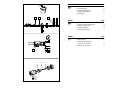
1.1 Montage
(Abb. 1)
1. Rohrleitung gut durchspülen.
2. Ventil 1 und 2 schließen.
3. Rückflussverhinderer 3 einbauen
● Einbaulage in waagrechte oder in Fließ-
richtung nach oben führende Rohrleitung
● Prüfstopfen 4 nach unten.
4. Ventil 1 und 2 langsam öffnen.
2. Instandhaltung (Abb. 2)
☞ Wir empfehlen dem Betreiber, einen
Wartungsvertrag mit einem Instal-
lationsunternehmen abzuschließen.
Entsprechend der DIN 1988, Teil 8 sind
folgende Maßnahmen regelmäßig durch-
zuführen:
Der Rückflussverhinderer muss jährlich
überprüft werden. Diese Überprüfung darf
vom Betreiber durchgeführt werden.
1. Absperrventil 1 schließen.
2. Prüfstopfen 4 öffnen.
Bis zur Druckentlastung wird etwas
Wasser am Prüfstopfen ausfließen.
Nach kurzer Zeit muss der Wasseraus-
fluss aufhören. Tropft oder läuft das
Wasser beständig weiter, so ist der
Rückflussverhinderer beschädigt oder
verschmutzt. Wenden Sie sich zur
Fehlerbeseitigung an Ihren Installateur.
3. Prüfstopfen 4 wieder schließen.
4. Absperrventil 1 wieder öffnen.
3. Verwendungsbereich
Anschlussgrößen
1
/2" - 2"
Medium Wasser, Pressluft*, mittlere und
leichte Heizöle, Kerosin, Benzin
mit Aromatenanteil unter 15%
GB
1. Installation
It is necessary during installation to observe
codes of good practice, to comply with local
requirements and to follow the installation
instructions. The installation location should
be protected against frost and be easily
accessible.
1.1 Assembly (Fig. 1)
1. Flush pipework thoroughly.
2. Close valve 1 and 2 .
3. Install the non return valve 3 .
● Install in horizontal or with flow
direction pointing upwards in vertical
pipework
● Test valve 4 pointing downwards
4. Slowly open valve 1 and 2 .
2. Maintenance (Fig. 2)
Planned maintenance is recommended
and DIN 1988, Part 8 specifies the
following operations:
The check valve must be tested once a
year. This can be done by the user.
1. Close shutoff valve 1 .
2. Open the test valve 4 .
Until the pressure has been relieved, a
little water will emit from the test valve.
Emission of water should stop after a
few moments. If water continues to drip
or run without stopping, then the check
valve is either damaged or dirty. This
should be corrected by a specialist.
3. Close test valve 4 .
4. Open shutoff valve 1 .
3. Scope of Application
Connection sizes
1
/2" - 2"
Medium Water, compressed air*,
medium and light heating
oils, Kerosene, petrol with
an aromatic content of less
than 15%
Operating pressure maximum 16 bar
Operating water up to 75 °C
temperature (for short period up to 90 °C)
Compressed air and
other mediums
Opening pressure approximately 0,05 bar
Not suitable for gaseous mediums
below 0.5 bar, not for steam, heavy
heating oil or Benzole
4. Safety Guidelines
1.Use the appliance
● In good condition
● According to regulations
● With due regard to safety
2.Follow installation instructions
3.Immediately rectify any malfunctions
which may influence safety.
4. RV280 non return valve is exclusively
for use in applications detailed in these
installation instructions.
Any variation from this or other use will
not comply with requirements.
5. Spare Parts (Fig. 5)
① Disc guide
1
/2" 5534900
3
/4" 5535100
1" 5531500 1
1
/4" 5535300
1
1
/2" 5535500 2" 5535700
② Compression spring
1
/2" 2061400
3
/4" 2061500
1" 2061600 1
1
/4" 2061700
1
1
/2" 2062000 2" 2062400
③ Sealing disc
1
/2" 0900356
3
/4" 0900357
1" 0900358 1
1
/4" 0900359
1
1
/2" 0900360 2" 0900361
④ Hexagon blanking
1
/2" - 2" S06M -
1
/4
with seals
(5 pieces)
*Im Rahmen der Anlagenzulassung nach PED muss auch
dieses Produkt als Teil der Anlage zertifiziert werden.
*As part of an installation being approved according to PED
requirements, this product must also be certified.

Inhaltsübersicht Seite
1. Einbau 2
2. Instandhaltung 2
3. Verwendungsbereich 2
4. Sicherheitshinweise 2
5. Ersatzteile 2
D
Index Page
1. Installation 3
2. Inspection and maintenance 3
3. Range of application 3
4. Safety guidelines 3
5. Replacement parts 3
GB
2
31
Index Page
1. Installation 3
2. Maintenance 3
3. Domaine d'application 3
4. Conseils de sécurité 3
5. Pièces de rechange 3
F
4
1.
2.
5.
①
④
③②
-
 1
1
-
 2
2
-
 3
3


in anderen Sprachen
- English: Honeywell RV280 Owner's manual
- français: Honeywell RV280 Le manuel du propriétaire
Verwandte Artikel
-
Honeywell RV281 Bedienungsanleitung
-
-
-
Honeywell RV277 Bedienungsanleitung
-
-
-
-
-
-