
Documentation IO-Link
A
-1200
Page 1 of 7 / 16.04.19
WIKA Alexander Wiegand SE & Co. KG
Alexander-Wiegand-Straße 30
63911 Klingenberg
Germany
Tel. +49 9372 132-0
Fax +49 9372 132-406
info@wika.de
www.wika.de
Kommanditgesellschaft: Sitz Klingenberg
Amtsgericht Aschaffenburg HRA 1819
Komplementärin: WIKA Verwaltungs SE & Co. KG
Sitz Klingenberg – Amtsgericht Aschaffenburg
HRA 4685
Komplementärin:
WIKA International SE - Sitz Klingenberg
Amtsgericht Aschaffenburg HRB 10505
Vorstand: Alexander Wiegand
Vorsitzender des Aufsichtsrats: Dr. Max Egli
Documentation IO-Link
Product: IO-Link pressure sensor, model A-1200
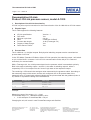
1. Description of the IO-Link functionality
IO-Link is a point-to-point connection for the communication of the A-1200 with an IO-Link master.
2. Physical layer
The A-1200 supports the following features:
IO-Link specification: Version 1.1
SIO mode: Yes
Minimum cycle time: 2,3 ms
Rate: COM2 (38.4 kBaud)
Process data length: 16 bit (Frametype 2.2)
Support of data storage: Yes
Smart Sensor Profile: Yes
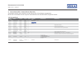
3. Process Data
The A-1200 has 1 or 2 digital outputs. Both physical switching outputs are also transmitted as
process data via IO-Link.
In the 'SIO Mode' (Standard I/O Mode, without IO-Link operation) the switching output 1 will switch
on pin 4 of the M12x1 connector. In the IO-Link communication mode, this pin 4 is reserved
exclusively for communication.
With a Frametype 2.2, the 16-bit process data from the pressure switch is transmitted cyclically.
Bit 0 is the state of switching output 1 and Bit 1 is the state of switching output 2, where 1
respectively DC 24 V correspond to the "closed" logic state of the respective output.
The remaining 14 Bit contain the analogue value measured by the pressure switch. According to
the measuring range of the sensor and the unit configured, the 14 Bit process data of the
measured value, is dynamically adjusted. Multiplying the process data with the gradient (Index #
67) allows for a pressure reading in the selected unit.
Example:
Measuring range of the sensor = 0 ... 10 psi
ProcessData range = 0...1,000 with Gradient = 0.01
In this example: ProcessData 500 = 5.0 psi
Changing the unit, will result in new ProcessData range and Gradient.
Bit Process value Value range
0 OU1 0 = inactive; 1 = active
1 OU2 0 = inactive; 1 = active
2 … 15 ProcessData -8192 ... 8191

Documentation IO-Link
A
-1200
Page 2 of 7 / 16.04.19
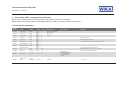
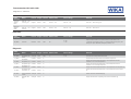
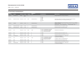
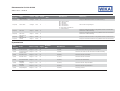
4. Service data (ISDU – Indexed Service Data Unit)
Service data is always acyclic and exchanged on the request of the IO-Link Master.
With the help of the service data, the following parameter values or instrument status can be read:
IO-Link specific parameters
Index
dez (hex)
Name Format Length Access Default value Value / Range Remarks
16 (0x10) Vendor Name StringT
max. 64
octets
R
WIKA Alexander Wiegand
SE & Co. KG
17 (0x11) Vendor Text StringT
max. 64
octets
R www.wika.com
18 (0x12) Product Name StringT
max. 64
octets
R A-1200
19 (0x13) Product ID StringT
max. 64
octets
R
-
Similar to DeviceID
20 (0x14) Product Text StringT
max. 64
octets
R - Additional product information.
21 (0x15) Serial Number StringT
max. 16
octets
R - Corresponds to serial number on the product label (S#...).
22 (0x16) Hardware Revision StringT
max. 64
octets
R -
23 (0x17) Firmware Revision StringT
max. 64
octets
R -
24 (0x18)
Application Specific
Tag
StringT
max. 32
octets
R/W -
Customer-specific measuring point name,
Allowed Characters: "A…Z"; "0…9"; "-"; <space>
32 (0x20) Error Count UIntegerT 2 octets R - Counts errors since power-on or reset.
36 (0x24) Device status UIntegerT 1 octet R -
0 = Device is OK
1 = Maintenance required
2 = Out of specification
3 = Functional check
4 = Failure
37 (0x25)
Detailed Device
Status
ArrayT of
OctetStringT3
24 octets R 00 00 00 h
Error storage

Documentation IO-Link
A
-1200
Page 3 of 7 / 16.04.19
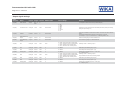
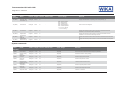
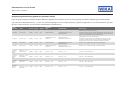
Output signal settings
Index
dez (hex)
Name Format Length Access Default value Value / Range Remarks
64 (0x40) Order Number StringT
max. 16
octets
R -
Corresponds to article number on the product label (P#...).
66 (0x42) Unit Process Data UIntegerT 1 octet R/W Order-related
0 = bar
1 = mbar
2 = MPa
3 = kPa
4 = PSI
5 = kg/cm²
6 = %
Selection of unit for ProcessData and all related parameters (switch point settings,
analogue output scaling, etc.)
67 (0x43) Gradient Float32T 4 octets R Order-related -
Factor for the calculation of the pressure reading. The factor could be any decimal
power.
ProcessData multiplied by the gradient = actual pressure in set unit
For example: 0...10 psi => ProcessData = 0…1000 with gradient: 0,01
68 (0x44)
Start of Measuring
Range
IntegerT 2 octets R Order-related - Start of measuring range in set ProcessData unit
69 (0x45)
End of Measuring
Range
IntegerT 2 octets R Order-related - End of measuring range in set ProcessData unit
70 (0x46) OU1 UIntegerT 1 octet R/W HNO
0 = HNO = hysteresis function normally open
1 = HNC = hysteresis function normally closed
2 = FNO = window function normally open
3 = FNC = window function normally closed
Switching function – switching output 1
71 (0x47) DS1 UIntegerT 2 octets R/W 0 0…65000 Switch delay time switching output 1 [ms]
72 (0x48) DR1 UIntegerT 2 octets R/W 0 0…65000 Reset delay time switching output 1 [ms]
73 (0x49) Damping OU1 UIntegerT 2 octets R/W 0 0…65000
Damping for the switching signal 1 ( = 99%) [ms].
0 = no damping active
80 (0x50) OU2 UIntegerT 1 octet R/W HNO
0 = HNO = hysteresis function normally open
1 = HNC = hysteresis function normally closed
2 = FNO = window function normally open
3 = FNC = window function normally closed
Switching function – switching output 2
Only available for devices with 2 switching outputs.
81 (0x51) DS2 UIntegerT 2 octets R/W 0 0…65000 Switch delay time switching output 2 [ms]
82 (0x52) DR2 UIntegerT 2 octets R/W 0 0…65000 Reset delay time switching output 2 [ms]
83 (0x53) Damping OU2 UIntegerT 2 octets R/W 0 0…65000
Damping for the switching signal 2 ( = 99%) [ms].
0 = no damping active

Documentation IO-Link
A
-1200
Page 4 of 7 / 16.04.19
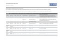
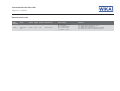
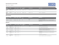
Output signal settings based on selected unit
Index 66 (0x42) “Unit ProcessData” defines which configurable parameters are shown in the IO-Link tool and which parameter is prioritized.
(e.g. Index 66 is set to “bar” -> Index 142-145 is shown and can be configured, any configuration in e.g. Index 202-205 in “psi” will be ignored.)
Index
dez (hex)
Name Format Length Access Default value Value / Range Remarks
142 (0x8E) SP1 / FH1_bar IntegerT 2 octets R/W End of measuring range
(Start of meas. range + 0.25 %) …
end of meas. range
Switching point (or window high) value
The value must always be higher than the reset point (or window low). The
minimum gap between these two points has a value of 0,25% of pressure range.
If the Gap is lower than the minimum hysteresis, the associate reset point will
automatically be changed to observe the limits.
143 (0x8F) RP1 / FL1_bar IntegerT 2 octets R/W
End of measuring range -
10% of range
Start of meas. range …
(end of meas. range - 0.25 %)
Reset point (or window low) value
The value must always be lower than the switch point (or window high). The
minimum gap between these two points has a value of 0,25% of pressure range.
If the Gap is lower than the minimum hysteresis, the associate switching point will
automatically be changed to observe the limits.
144 (0x90) SP2 / FH2_bar IntegerT 2 octets R/W End of measuring range
(Start of meas. range + 0.25 %) …
end of meas. range
See SP1 / FH1, only available for devices with 2 switching outputs.
145 (0x91) RP2 / FL2_bar IntegerT 2 octets R/W
End of measuring range -
10% of range
Start of meas. range …
(end of meas. range - 0.25 %)
See RP1 / FL1, only available for devices with 2 switching outputs.
157 to 160
(0x9D to
0xA0)
Index 142 … 145
in Unit “mbar”
IntegerT 2 octets R/W See 142 … 145 See 142 … 145 Index 142 … 145 in Unit “mbar”
172 to 175
(0xAC to
0xAF)
Index 142 … 145
in Unit “MPa”
IntegerT 2 octets R/W See 142 … 145 See 142 … 145
Index 142 … 145 in Unit “MPa”
187 to 190
(0xBB to
0xBE)
Index 142 … 145
in Unit “kPa”
IntegerT 2 octets R/W See 142 … 145 See 142 … 145 Index 142 … 145 in Unit “kPa”
202 to 205
(0xCA to
0xCD)
Index 142 … 145
in Unit “PSI”
IntegerT 2 octets R/W See 142 … 145 See 142 … 145 Index 142 … 145 in Unit “PSI”

Documentation IO-Link
A
-1200
Page 5 of 7 / 16.04.19
Index
dez (hex)
Name Format Length Access Default value Value / Range Remarks
217 to 220
(0xD9 to
0xDC)
Index 142 … 145
in Unit “kg_cm²”
IntegerT 2 octets R/W See 142 … 145 See 142 … 145 Index 142 … 145 in Unit “kg_cm²”
232 to 235
(0xE8 to
0xEB)
Index 142 … 145
in Unit “%”
IntegerT 2 octets R/W See 142 … 145 See 142 … 145 Index 142 … 145 in Unit “%”
Indication
Index
dez (hex)
Name Format Length Access Default value Value / Range Remarks
106 (0x6A) Locate me BooleanT 1 octet R/W Off
0 = Off
1 = On
Helps to locate the device on a machine, flashes the LED indicator in red.
"Locate Me" has the highest priority, e.g. a warning would have less priority. The
flashing can only be disabled by setting the parameter to "off".
Diagnosis
Index
dez (hex)
Name Format Length Access Default value Value / Range Remarks
110 (0x6E) Temperature Unit UIntegerT 1 octet R/W °C
0 = °C
1 = °F
Unit of the internal temperature measurement.
111 (0x6F)
Actual
Temperature
Float32T 4 octets R - Internal temperature measurement of the electronic components.
112 (0x70) Temperature Low Float32T 4 octets R -
Displays the minimum temperature value in unit of temperature since first
installation / since “reset low temperature”.
113 (0x71) Temperature High Float32T 4 octets R -
Displays the maximum temperature value in unit of temperature since first
installation / since “reset high temperature”.
114 (0x72)
Temperature Low
since Power Up
Float32T 4 octets R - Displays the minimum temperature value in unit of temperature since last power-up.
115 (0x73)
Temperature High
since Power Up
Float32T 4 octets R -
Displays the maximum temperature value in unit of temperature since last power-
up.
120 (0x78)
Pressure Overload
Counter
UIntegerT 4 octets R - Duration in Pressure Overload Range [s]
121 (0x79)
Operating Hours
Total
UIntegerT 4 octets R - Displays the total amount of operating hours since first installation. [h]

Documentation IO-Link
A
-1200
Page 6 of 7 / 16.04.19
Index
dez (hex)
Name Format Length Access Default value Value / Range Remarks
122 (0x7A)
Operating Hours
since Power Up
UIntegerT 4 octets R - Displays the total amount of operating hours since power-up. [h]
123 (0x7B) Sensor Status UIntegerT 1 octet R -
Bit0 = Sensor is defect
Bit1 = Overpressure
Bit2 = Underpressure
Bit3 = Overtemperature
Bit4 = Undertemperature
„0“ = no error / warning
„1“ = error / warning
Status of sensor self-diagnosis
124 (0x7C) Low Pressure IntegerT 2 octets R
Displays the minimum pressure value in set unit of ProcessData since first
installation / since reset with "Reset Low Pressure"
125 (0x7D) High Pressure IntegerT 2 octets R
Displays the maximum pressure value in set unit of ProcessData since first
installation / since reset with "Reset High Pressure"
126 (0x7E)
Low Pressure
since
Power Up
IntegerT 2 octets R
Displays the minimum pressure value in set unit of ProcessData since last power-
up.
127 (0x7F)
High Pressure
Since Power Up
IntegerT 2 octets R
Displays the maximum pressure value in set unit of ProcessData since last power-
up.
System commands
Index
dez (hex)
Name Format Length Access Default value Value / Range Remarks
2 (0x02) Device Reset UIntegerT 1 octet W - 128 (0x80) This feature restarts the device without change of parameters.
2 (0x02)
Restore Factory
Settings
UIntegerT 1 octet W - 130 (0x82) Restores the device to factory settings.
2 (0x02)
Reset High
Pressure
UIntegerT 1 octet W - 160 (0xA0) Resets the high pressure counter.
2 (0x02)
Reset Low
Pressure
UIntegerT 1 octet W - 161 (0xA1) Resets the low pressure counter.
2 (0x02)
Reset Pressure
Overload Counter
UIntegerT 1 octet W - 162 (0xA2) Clears the overload counter to zero.
2 (0x02)
Reset High
Temperature
UIntegerT 1 octet W - 163 (0xA3) Resets the high temperature counter.
2 (0x02)
Reset Low
Temperature
UIntegerT 1 octet W - 164 (0xA4) Resets the low temperature counter.
2 (0x02) Adjust Zero Point UIntegerT 1 octet W - 165 (0xA5) Performs an "Autozero"

Documentation IO-Link
A
-1200
Page 7 of 7 / 16.04.19
Device Access Locks
Index
dez (hex)
Name Format Length Access Default value Value / Range Remarks
12 (0x0C)
Device Access
Locks
RecordT 2 octets R/W 00 00 h (unlocked)
Bit 0: Parameter (write) access
Bit 1: Data Storage
Bit 2: Local Parametrization
Bit 3: Local User Interface
0 = Unlocked, 1 = Locked
Bit 0: Disables change of parameters via IO-Link
Bit 1: Disables data storage mechanism
Bit 2: Disable change of parameters via buttons on the device
Bit 3: Disable access on the menu via buttons on the device

Dokumentation IO-Link
A
-1200
Seite 1 von 7 / 16.04.19
WIKA Alexander Wiegand SE & Co. KG
Alexander-Wiegand-Straße 30
63911 Klingenberg
Germany
Tel. +49 9372 132-0
Fax +49 9372 132-406
info@wika.de
www.wika.de
Kommanditgesellschaft: Sitz Klingenberg
Amtsgericht Aschaffenburg HRA 1819
Komplementärin: WIKA Verwaltungs SE & Co. KG
Sitz Klingenberg – Amtsgericht Aschaffenburg
HRA 4685
Komplementärin:
WIKA International SE - Sitz Klingenberg
Amtsgericht Aschaffenburg HRB 10505
Vorstand: Alexander Wiegand
Vorsitzender des Aufsichtsrats: Dr. Max Egli
Dokumentation IO-Link
Produkt: IO-Link Drucksensor mit IO-Link, Typ A-1200
1. Beschreibung der IO-Link Funktionalität
IO-Link ist eine Punkt-zu-Punkt-Verbindung zwischen dem A-1200 und einem IO-Link Master.
2. Physikalische Schicht
Der A-1200 unterstützt folgende Eigenschaften:
IO-Link Spezifikation: Version 1.1
SIO Modus: Ja
Minimale Zykluszeit: 2,3 ms
Geschwindigkeit: COM2 (38,4 kBaud)
Prozessdatenbreite: 16 bit (Frametyp 2.2)
Unterstützung Datenhaltung: Ja
Smart Sensor Profile: Ja
3. Prozessdaten
Der A-1200 hat 1 oder 2 digitale Ausgänge. Beide Schaltausgänge werden als Prozessdaten über
IO-Link übertragen.
Im sogenannten SIO-Modus (Standard I/O Modus), d. h. kein IO-Link Betrieb, wird der
Schaltausgang 1 am Pin 4 des M12 Steckers geschaltet. Im IO-Link Kommunikationsbetrieb ist
dieser Pin ausschließlich der Kommunikation vorbehalten.
Bei einem Frametyp 2.2 werden 16-Bit Prozessdaten des Druckschalters zyklisch übertragen. Bit 0
gibt den Zustand des Schaltausgangs 1 und das Bit 1 den Zustand des Schaltausgangs 2 wieder.
Dabei entspricht 1 bzw. DC 24 V dem logischen Zustand „geschlossen“ auf dem entsprechenden
Ausgang.
Die verbleibenden 14 Bit enthalten den analogen Messwert des Druckschalters. Entsprechend
dem Messbereich des Drucksensors und der konfigurierten Einheit, werden die 14 Bit Prozess-
daten dynamisch angepasst. Die Multiplikation des Messwertes mit dem Gradient (Index # 67)
liefert den Messwert in der gewählten Druck-Einheit.
Beispiel:
Messbereich des Sensors = 0 ... 10 bar
Prozesswert = 0...1,000
Gradient = 0.01
Beispiel: Prozesswert 500 = 5,00 bar
Ein Wechsel der Einheit, ändert den Wertebereich des 14 Bit Messwertes und Gradienten.
Bit Prozesswert Wertebereich
0 OU1 0 = aus, 1 = an
1 OU2 0 = aus, 1 = an
2 ... 15 Messwert -8192 ... 8191

Dokumentation IO-Link
A
-1200
Seite 2 von 7 / 16.04.19
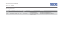
4. Servicedaten (ISDU – Indexed Service Data Unit)
Servicedaten werden immer azyklisch und auf Anfrage des IO-Link Masters ausgetauscht.
Mit Hilfe der Servicedaten können folgende Parameterwerte oder Gerätezustände ausgelesen werden:
IO-Link spezifisch
Index
dez (hex)
Name Format Länge Zugriff
Standard
Wert
Wertebereich Bemerkung
16 (0x10) Herstellername StringT
max. 64
octets
R
WIKA Alexander Wiegand
SE & Co. KG
17 (0x11) Herstellertext StringT
max. 64
octets
R www.wika.com
18 (0x12) Produktname StringT
max. 64
octets
R A-1200
19 (0x13) Produkt-ID StringT
max. 64
octets
R
-
Entspricht der DeviceID
20 (0x14) Produkttext StringT
max. 64
octets
R - Zusätzliche Produktinformation
21 (0x15) Seriennummer StringT
max. 16
octets
R - Entspricht Seriennummer auf Typenschild (S#).
22 (0x16) Hardwareversion StringT
max. 64
octets
R -
23 (0x17) Firmwareversion StringT
max. 64
octets
R -
24 (0x18)
Anwendungs-
spezifische
Markierung
StringT
max. 32
octets
R/W -
Kundenspezifische Messstellennummer
Zulässige Eingaben: "A…Z"; "0…9"; "-"; <Leerzeichen>
32 (0x20) Fehlerzähler UIntegerT 2 octets R - Fehlerzähler seit Neustart oder Rücksetzen auf Werkskonfiguration
36 (0x24) Gerätestatus UIntegerT 1 octet R -
0 = Gerät ist OK
1 = Wartung erforderlich
2 = Außerhalb der Spezifikation
3 = Funktionsprüfung
4 = Fehler
37 (0x25)
Ausführlicher
Gerätestatus
ArrayT of
OctetStringT3
24 octets R 00 00 00 h
Fehlerspeicher

Dokumentation IO-Link
A
-1200
Seite 3 von 7 / 16.04.19
Einstellung Ausgangssignal
Index
dez (hex)
Name Format Länge Zugriff
Standard
Wert
Wertebereich Bemerkung
64 (0x40) Artikelnummer StringT
max. 16
octets
R -
Entspricht Artikelnummer auf Typenschild (P#).
66 (0x42) Einheit Prozesswert UIntegerT 1 octet R/W Gemäß Bestellung
0 = bar
1 = mbar
2 = MPa
3 = kPa
4 = PSI
5 = kg/cm²
6 = %
Auswahl der Einheit der Prozessdaten und aller abhängigen Parameter
(Schaltpunkteinstellung, Analogausgangsskalierung, etc.)
67 (0x43) Gradient Float32T 4 octets R Gemäß Bestellung -
Faktor zur Berechnung des Druckmesswertes. Der Faktor kann eine beliebige
Dezimale annehmen.
Messwert multipliziert mit dem Gradient = aktueller Druck in gewählter Einheit
Zum Beispiel: 0 ... 10 bar => Messwert = 0 … 1.000 mit Gradient: 0,01
68 (0x44) Messbereichsanfang IntegerT 2 octets R Gemäß Bestellung - Messbereichsanfang in konfigurierter Einheit
69 (0x45) Messbereichsende IntegerT 2 octets R Gemäß Bestellung - Messbereichsende in konfigurierter Einheit
70 (0x46) OU1 UIntegerT 1 octet R/W HNO
0 = HNO = Hysteresefunktion Schließer
1 = HNC = Hysteresefunktion Öffner
2 = FNO = Fensterfunktion Schließer
3 = FNC = Fensterfunktion Öffner
Schaltfunktion Schaltausgang 1
71 (0x47) DS1 UIntegerT 2 octets R/W 0 0…65000 Schaltverzögerungszeit Schaltpunkt 1 [ms]
72 (0x48) DR1 UIntegerT 2 octets R/W 0 0…65000 Schaltverzögerungszeit Rückschaltpunkt 1 [ms]
73 (0x49) Dämpfung OU1 UIntegerT 2 octets R/W 0 0…65000
Dämpfung für Schaltausgang 1 ( = 99%) [ms].
0 = keine aktive Dämpfung
80 (0x50) OU2 UIntegerT 1 octet R/W HNO
0 = HNO = Hysteresefunktion Schließer
1 = HNC = Hysteresefunktion Öffner
2 = FNO = Fensterfunktion Schließer
3 = FNC = Fensterfunktion Öffner
Schaltfunktion Schaltausgang 2
Verfügbar für Geräte mit 2 Schaltausgängen.
81 (0x51) DS2 UIntegerT 2 octets R/W 0 0…65000 Schaltverzögerungszeit Schaltpunkt 2 [ms]
82 (0x52) DR2 UIntegerT 2 octets R/W 0 0…65000 Schaltverzögerungszeit Rückschaltpunkt 2 [ms]
83 (0x53) Dämpfung OU2 UIntegerT 2 octets R/W 0 0…65000
Dämpfung für Schaltausgang 2 ( = 99%) [ms].
0 = keine aktive Dämpfung

Dokumentation IO-Link
A
-1200
Seite 4 von 7 / 16.04.19
Ausgangssignaleinstellung gemäß der gewählten Einheit
Index 66 (0x42) “Einheit Prozesswert” definiert welche konfigurierbaren Parameter im IO-Link-Tool angezeigt und welche Einstellungen priorisiert werden.
(z.B. Index 66 ist eingestellt auf “bar” -> Index 142-145 wird angezeigt und kann konfiguriert werden, jegliche Konfiguration in z. B. Index 202-205 in “psi” wird
ignoriert, sowohl im IO-Link-Tool als auch bei Indexbasierter Parametrierung.)
Index
dez (hex)
Name Format Länge Zugriff
Standard
Wert
Wertebereich Bemerkung
142 (0x8E) SP1 / FH1_bar IntegerT 2 octets R/W Messbereichsende
(Messbereichsanfang + 0,25 %) …
Messbereichsende
Schaltpunkt /Fenster High Schaltausgang 1
Der Wert muss immer höher als der Rückschaltpunkt bzw. Fenster Low sein. Der
minimale Unterschied liegt bei 0.25 % des Messbereiches. Bei Einstellung kleiner
0.25 % wird der Rückschaltpunkt automatisch angepasst.
143 (0x8F) RP1 / FL1_bar IntegerT 2 octets R/W
Messbereichsende - 10%
der Spanne
Messbereichsanfang …
(Messbereichsende – 0,25 %)
Rückschaltpunkt /Fenster Low Schaltausgang 1
Der Wert muss immer niedriger als der Schaltpunkt bzw. Fenster High sein
The value must always be lower than the switch point (or window high). Bei
Einstellung kleiner 0.25 % wird der Schaltpunkt automatisch angepasst.
144 (0x90) SP2 / FH2_bar IntegerT 2 octets R/W Messbereichsende
(Messbereichsanfang + 0,25 %) …
Messbereichsende
Siehe SP1 / FH1, verfügbar für Geräte mit 2 Schaltausgängen
145 (0x91) RP2 / FL2_bar IntegerT 2 octets R/W
Messbereichsende - 10%
der Spanne
Messbereichsanfang …
(Messbereichsende – 0,25 %)
Siehe RP1 / FL1, verfügbar für Geräte mit 2 Schaltausgängen
157 to 160
(0x9D to
0xA0)
Index 142 … 145 in
Einheit “mbar”
IntegerT 2 octets R/W Siehe 142 … 145 Siehe 142 … 145 Index 142 … 145 in Einheit “mbar”
172 to 175
(0xAC to
0xAF)
Index 142 … 145 in
Einheit “MPa”
IntegerT 2 octets R/W Siehe 142 … 145 Siehe 142 … 145 Index 142 … 145 in Einheit “MPa”
187 to 190
(0xBB to
0xBE)
Index 142 … 145 in
Einheit “kPa”
IntegerT 2 octets R/W Siehe 142 … 145 Siehe 142 … 145 Index 142 … 145 in Einheit “kPa”
202 to 205
(0xCA to
0xCD)
Index 142 … 145 in
Einheit “PSI”
IntegerT 2 octets R/W Siehe 142 … 145 Siehe 142 … 145 Index 142 … 145 in Einheit “PSI”

Dokumentation IO-Link
A
-1200
Seite 5 von 7 / 16.04.19
Index
dez (hex)
Name Format Länge Zugriff
Standard
Wert
Wertebereich Bemerkung
217 to 220
(0xD9 to
0xDC)
Index 142 … 145 in
Einheit “kg_cm²”
IntegerT 2 octets R/W Siehe 142 … 145 Siehe 142 … 145 Index 142 … 145 in Einheit “kg_cm²”
232 to 235
(0xE8 to
0xEB)
Index 142 … 145 in
Einheit “%”
IntegerT 2 octets R/W Siehe 142 … 145 Siehe 142 … 145 Index 142 … 145 in Einheit “%”
Statusanzeige
Index
dez (hex)
Name Format Länge Zugriff
Standard
Wert
Wertebereich Bemerkung
106 (0x6A) Lokalisator BooleanT 1 octet R/W Off
0 = Aus
1 = An
Unterstützt die Lokalisierung des Gerätes in einer Maschine, durch Blinken der
Statusanzeige in der Farbe Rot.
Der "Lokalisator" hat die höchste Priorität, d.h. z.B. eine Warnung (gelb) hat
niedrigere Priorität. Der Modus kann nur durch Einstellung des Parameters auf “off”
deaktiviert werden.
Diagnose
Index
dez (hex)
Name Format Länge Zugriff
Standard
Wert
Wertebereich Bemerkung
110 (0x6E) Temperatureinheit UIntegerT 1 octet R/W °C
0 = °C
1 = °F
Einheit der internen Temperaturmessung.
111 (0x6F)
Aktuelle
Elektroniktemperatur
Float32T 4 octets R - Interne Temperaturmessung der Elektronik.
112 (0x70) Min. Temperatur Float32T 4 octets R -
Anzeige der minimalen Elektroniktemperatur in der gewählten Einheit seit
Erstinstallation / Zurücksetzen auf Werkseinstellung.
113 (0x71) Max. Temperatur Float32T 4 octets R -
Anzeige der maximalen Elektroniktemperatur in der gewählten Einheit seit
Erstinstallation / Zurücksetzen auf Werkseinstellung.
114 (0x72)
Min. Temperatur seit
Neustart
Float32T 4 octets R -
Anzeige der minimalen Elektroniktemperatur in der gewählten Einheit seit
Geräteneustart.
115 (0x73)
Max. Temperatur seit
Neustart
Float32T 4 octets R -
Anzeige der maximalen Elektroniktemperatur in der gewählten Einheit seit
Geräteneustart.
120 (0x78) Überlastzahler UIntegerT 4 octets R - Gesamtdauer im Überlastbereich [s]
121 (0x79)
Betriebsstunden-
zähler
UIntegerT 4 octets R - Anzeige des Betriebsstundenzählers seit Erstinstallation. [h]

Dokumentation IO-Link
A
-1200
Seite 6 von 7 / 16.04.19
Index
dez (hex)
Name Format Länge Zugriff
Standard
Wert
Wertebereich Bemerkung
122 (0x7A)
Betriebsstunden-
zähler seit Neustart
UIntegerT 4 octets R - Anzeige des Betriebsstundenzählers seit Geräteneustart. [h]
123 (0x7B) Sensor Status UIntegerT 1 octet R -
Bit0 = Sensor ist defekt
Bit1 = Überdruck
Bit2 = Unterdruck
Bit3 = Übertemperatur
Bit4 = Untertemperatur
„0“ = Kein Fehler / Keine Warnung
„1“ = Fehler / Warnung
Status der Sensor-Eigendiagnose
124 (0x7C) Min. Druck IntegerT 2 octets R
Anzeige des minimalen Druckwertes in der gewählten Einheit seit Erstinstallation /
Zurücksetzen auf Werkseinstellung.
125 (0x7D) Max. Druck IntegerT 2 octets R
Anzeige des maximalen Druckwertes in der gewählten Einheit seit Erstinstallation /
Zurücksetzen auf Werkseinstellung.
126 (0x7E)
Min. Druck seit
Neustart
IntegerT 2 octets R Anzeige des minimalen Druckwertes in der gewählten Einheit seit Geräteneustart.
127 (0x7F)
Max. Druck seit
Neustart
IntegerT 2 octets R
Anzeige des maximalen Druckwertes in der gewählten Einheit seit Geräteneustart.
Systembefehle
Index
dez (hex)
Name Format Länge Zugriff
Standard
Wert
Wertebereich Bemerkung
2 (0x02) Geräte rücksetzen UIntegerT 1 octet W - 128 (0x80) Geräteneustart ohne Änderung / Rücksetzen der Parameter
2 (0x02)
Auslieferungszustand
wiederherstellen
UIntegerT 1 octet W - 130 (0x82) Rücksetzen des Gerätes und aller Parameter auf die Werkseinstellung
2 (0x02) Reset Max. Druck UIntegerT 1 octet W - 160 (0xA0) Rücksetzen des Max. Druckzählers
2 (0x02) Reset Min. Druck UIntegerT 1 octet W - 161 (0xA1) Rücksetzen des Min. Druckzählers
2 (0x02) Reset Überlastzähler UIntegerT 1 octet W - 162 (0xA2) Rücksetzen des Überlastzählers
2 (0x02)
Reset Max.
Temperatur
UIntegerT 1 octet W - 163 (0xA3) Rücksetzen des Max. Temperaturzählers
2 (0x02)
Reset Min.
Temperatur
UIntegerT 1 octet W - 164 (0xA4) Rücksetzen des Min. Temperaturzählers
2 (0x02) Nullpunktabgleich UIntegerT 1 octet W - 165 (0xA5) Ausführung „Autozero“

Dokumentation IO-Link
A
-1200
Seite 7 von 7 / 16.04.19
Gerätezugriffssperren
Index
dez (hex)
Name Format Länge Zugriff
Standard
Wert
Wertebereich Bemerkung
12 (0x0C)
Gerätezugriffssperren
RecordT 2 octets R/W 00 00 h (unlocked)
Bit 0: Parameter (Schreib) Zugriffssperre
Bit 1: Datenspeicherungssperre
Bit 2: Lokale Parametrisierungssperre
Bit 3: Lokale Benutzer-Interface-Sperre
0 = Entsperrt, 1 = Gesperrt
Bit 0: Deaktiviert die Parameteränderung via IO-Link
Bit 1: Deaktiviert den Data Storage Mechanismus
Bit 2: Deaktiviert die Parameteränderung via der Gerätetastatur
Bit 3: Deaktiviert den Menüzugriff über die Gerätetastatur
-
 1
1
-
 2
2
-
 3
3
-
 4
4
-
 5
5
-
 6
6
-
 7
7
-
 8
8
-
 9
9
-
 10
10
-
 11
11
-
 12
12
-
 13
13
-
 14
14


in anderen Sprachen
- English: WIKA A-1200 Operating instructions
Verwandte Artikel
Andere Dokumente
-
Datalogic S5N-MR RADIAL Benutzerhandbuch
-
CARLO GAVAZZI LD30ETBI10BPM5IO Benutzerhandbuch
-
CARLO GAVAZZI CA18FAF08BPA2IO Benutzerhandbuch
-
-
IFM PP0522 Bedienungsanleitung
-
Toro Hourmeter Kit, 2011 and After TimeCutter Riding Mower Installationsanleitung
-
IFM SB1234 Bedienungsanleitung
-
AVENTICS Distance measuring sensor Bedienungsanleitung
-
 Kromschroder DGS Datenblatt
