Magnescale MT13 / MT14 Bedienungsanleitung
- Typ
- Bedienungsanleitung

MT12 / MT13 / MT14
Instruction Manual / Bedienungsanleitung
Read all the instructions in the manual carefully before use and strictly follow them.
Keep the manual for future references.
Lesen Sie die ganze Anleitung vor dem Betrieb aufmerksam durch und folgen Sie beim
Betrieb des Geräts den Anweisungen. Bewahren Sie diese Bedienungsanleitung zum
späteren Nachlesen griffbereit auf.

[For U.S.A. and Canada]
THIS CLASS A DIGITAL DEVICE COMPLIES WITH
PART15 OF THE FCC RULES AND THE CANADIAN
ICES-003. OPERATION IS SUBJECT TO THE
FOLLOWING TWO CONDITIONS.
(1) THIS DEVICE MAY NOT CAUSE HARMFUL
INTERFERENCE, AND
(2) THIS DEVICE MUST ACCEPT ANY
INTERFERENCE RECEIVED, INCLUDING
INTERFERENCE THAT MAY CAUSE
UNDERSIGNED OPERATION.
CET APPAREIL NUMÉRIQUE DE LA CLASSE A
EST CONFORME À LA NORME NMB-003 DU
CANADA.

MT12 / MT13 / MT14
(J) (1)

(2) (J)
MT12 / MT13 / MT14
•
•
•
•

MT12 / MT13 / MT14
(J) 1
•
•
•
•
•
•
•°

2 (J)
MT12 / MT13 / MT14
µ µ
µ
µ

MT12 / MT13 / MT14
(J) 3
±
Ω
+°
– + °
µ
<<<
< < <
< < <
< <
<
<
µ

4 (J)
MT12 / MT13 / MT14
+
+

MT12 / MT13 / MT14
(J) 5
+

6 (J)
MT12 / MT13 / MT14

MT12 / MT13 / MT14
(E) (1)
Magnescale Co., Ltd. products are designed in full consideration of safety. However,
improper handling during operation or installation is dangerous and may lead to fire, electric
shock or other accidents resulting in serious injury or death. In addition, these actions may
also worsen machine performance.
Therefore, be sure to observe the following safety precautions in order to prevent these types
of accidents, and to read these "Safety Precautions" before operating, installing, maintaining,
inspecting, repairing or otherwise working on this unit.
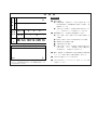
Warning Indication Meanings
The following indications are used throughout this manual, and their contents should be
understood before reading the text.
Failure to observe these precautions may lead to fire, electric shock or other accidents
resulting in serious injury or death.
Failure to observe these precautions may lead to electric shock or other accidents resulting in
injury or damage to surrounding objects.
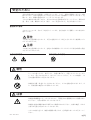
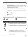
Safety Precautions
Warning
Caution
CAUTION DO NOT
DISASSEMBLE
ELECTRICAL
SHOCK
Symbols requiring attention
Warning
•Do not damage, modify, excessively bend, pull on, place heavy objects on or heat the
cable, as this may damage the cable and result in fire or electric shock.
•Do not disassemble or modify the unit, as this may result in injury or electric shock.
These actions may also damage the internal circuitry.
Caution
•The unit does not have an explosion-proof structure. Therefore, do not use the unit in
an atmosphere charged with inflammable gases as this may result in fire.
•Do not use the unit in places where it may receive excessive shocks. Otherwise the
inside of the unit may be damaged or the unit may become unable to produce normal
output signals.
•Be sure to turn off the power before connecting or disconnecting connectors in oder to
prevent damage or misoperation.
Symbols prohibiting actions

(2) (E)
MT12 / MT13 / MT14
General precautions
When using Magnescale Co., Ltd. products, observe the
following general precautions along with those given
specifically in this manual to ensure proper use of the
products.
•Before and during operations, be sure to check that our
products function properly.
•Provide adequate safety measures to prevent damages
in case our products should develop malfunctions.
•Use outside indicated specifications or purposes and
modification of our products will void any warranty of the
functions and performance as specified of our products.
•When using our products in combination with other
equipment, the functions and performances as noted in
this manual may not be attained, depending on operating
and environmental conditions.

MT12 / MT13 / MT14
(E) 1
Operating Cautions
•Do not route the connecting cable through the same duct as the machine power line.
•Take preventive steps when the noises from other equipment may disturb the power supply line to the
units.
•When providing DC power, be sure to use within the specified voltage range.
•Do not pull the cable forcibly or pull at the cable when you connect or disconnect it. Such handling may
cause a break in the line.
•Be sure to ground the measuring unit’s frame to prevent misoperation due to noise or static electricity.
•For installation of the interpolator, avoid a location exposed to chips, cutting oil, or machine oil.
If unavoidable, take adequate countermeasures.
•The ambient temperature should be in the range of 0
°C to 50
°C (32
°F to 122
°F). Avoid exposure to
direct sunlight, hot air currents, or heated air.

2 (E)
MT12 / MT13 / MT14
Outline
MT12, MT13, and MT14 are interpolators for use with the DT series measuring unit.
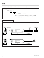
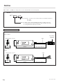
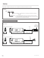
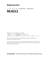
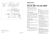
Parts name and Dimensions
Output resolution 01 : 1 µm (The 1 µm resolution model is not available in the MT12.)
05 : 5 µm
10 : 10 µm
Model 12 : Open collector output mini-DIN 10-pin cable (for LT20A counter unit)
13 : Voltage differential output mini-DIN 8-pin cable (for LT30 counter unit)
14 : Voltage differential output open-end cable
MT
Model
Measuring unit connector
MT12 / MT13
MT14
Unit : mm/inch
25/0.98"
32/1.26"
98/3.86" Cable length : 300/11.81"
Cable
Counter unit
connector
Measuring unit connector
25/0.98"
32/1.26"
98/3.86" Cable length : 300/11.81"
Cable

MT12 / MT13 / MT14
(E) 3
LSpecifications
Model MT12-05/10 MT13-01/05/10 MT14-01/05/10
Compatible measuring units DT512/DT12/DT32
Maximum response speed 100 m/min
Power voltage DC5 V ±4 %
Power consumption 0.9 W 1.2 W (when output load of 120Ω is
connected)
Output format NPN open collector Voltage differential line driver
Operating temperature and humidity range 0 to +50 °C (no condensation)
Storage temperature and humidity range –10 to +60 °C (20 to 90 %RH)
Dimensions See the Dimensional Diagram.
Mass About 90 g
Specifications and appearances of the products are subject to change without notice because of
improvement.
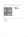
LPhase difference for A/B phase output
Changes as follows according to the traveling velocity of the measuring unit.
Model MTMM-01 MTMM-05 MTMM-10 Output phase difference (µs)
Velocity : 0 < v 2.5 0 < v 12.5 0 < v 25 20
v (m/min) 2.5 < v 6.25 12.5 < v 31.25 25 < v 62.5 8
6.25 < v 12 31.25 < v 60 62.5 < v (100) ∗5
12 < v 24 60 < v (100) ∗–2.5
24 < v 60 – – 1
60 < v (100) ∗–– 0.5
∗An alarm is output at a traveling velocity of 100 to 115 m/min.
The sampling frequency of the output signal is 120 µs.
LAlarm signal
This signal is output when the response acceleration is exceeded or when a measuring unit is not connected.
The minimum output pulse width is 10 ms, and the alarm output signal also recovers automatically
when the alarm status is canceled.
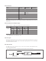
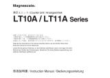
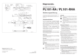
LCable extension
The CE08 extension cable (optional accessory) can be used to extend the cable length between the
measuring unit and interpolator.
∗Use a cable that is 15 m or less in length between the interpolator and measuring unit.
DT512/DT12/DT32 Interpolator MT12/MT13/MT14
15 m or less

4 (E)
MT12 / MT13 / MT14
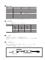
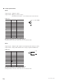
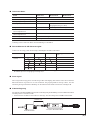
LOutput specifications
MT12
Output signal : A/B phase, Alarm
Output format : NPN open collector output
(maximum rated voltage: 31 V, maximum rated current: 50 mA)
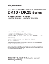
Cable color
Pin no. Description Cable color
1+5 V Red
2–
30 V Black
4AYellow
5BBlue
6–
7–
8ALARM Gray
90 V Purple
10 0 V Orange
Case FG Shield
Connector used: Hosiden TCP8938 or equivalent product
0V and the shield (FG) are connected with a capacitor.
Nothing should be connected to cables with colors not found in this table.
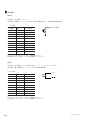
MT13
Output signal : A/B phase (The output becomes high impedance during an alarm.)
Output format : Voltage differential line driver output (compliant with EIA-422)
Cable color
Pin no. Description Cable color
1+5 V Purple
20 V Black
3ABlue
4AYellow
5BOrange
6BGray
7–
8–
Case FG Shield
Connector used: Hosiden TCP6182 or equivalent product
0V and the shield (FG) are connected with a capacitor.
Nothing should be connected to cables with colors not found in this table.
A, B, ALARM
A, B
A, B

MT12 / MT13 / MT14
(E) 5
A, B, ALARM
A, B, ALARM
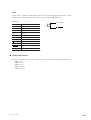
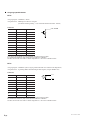
MT14
Output signal : A/B phase, Alarm (The output does not become high impedance during an alarm.)
Output format : Voltage differential line driver output (compliant with EIA-422)
Cable color
Description Cable color
+5 V Red
0 V White
0 V Brown
0 V Black
AYellow
ABlue
BGray
BOrange
ALARM Purple
ALARM Green
FG Shield
0V and the shield (FG) are connected with a capacitor.
LOptional Accessories
Extension cable (These are extension cables for use between measuring unit and the interpolator.)
CE08-1 (1 m)
CE08-3 (3 m)
CE08-5 (5 m)
CE08-10 (10 m)
CE08-15 (15 m)

6 (E)
MT12 / MT13 / MT14

(G) (1)
MT12 / MT13 / MT14
Sicherheitsmaßnahmen
Bei dem Entwurf von Magnescale Co., Ltd. Produkten wird größter Wert auf die Sicherheit
gelegt. Unsachgemäße Handhabung während des Betriebs oder der Installation ist jedoch
gefährlich und kann zu Feuer, elektrischen Schlägen oder anderen Unfällen führen, die
schwere Verletzungen oder Tod zur Folge haben können. Darüber hinaus kann falsche
Behandlung die Leistung der Maschine verschlechtern.
Beachten Sie daher unbedingt die besonders hervorgehobenen Vorsichtshinweise in dieser
Bedienungsanleitung, um derartige Unfälle zu verhüten, und lesen Sie die folgenden
Sicherheitsmaßnahmen vor der Inbetriebnahme, Installation, Wartung, Inspektion oder
Reparatur dieses Gerätes oder der Durchführung anderer Arbeiten durch.
Bedeutung der Warnhinweise
Bei der Durchsicht dieses Handbuchs werden Sie auf die folgenden Hinweise und Symbole
stoßen. Machen Sie sich mit ihrer Bedeutung vertraut, bevor Sie den Text lesen.
Eine Missachtung dieser Hinweise kann zu Feuer, elektrischen Schlägen oder anderen
Unfällen führen, die schwere Verletzungen oder Tod zur Folge haben können.
Eine Missachtung dieser Hinweise kann zu elektrischen Schlägen oder anderen Unfällen
führen, die Verletzungen oder Sachbeschädigung der umliegenden Objekte zur Folge haben
können.
Warnung
Vorsicht
VORSICHT NICHT
ZERLEGEN
Zu beachtende Symbole
ELEKTRISCHER
SCHLAG
Warnung
•Das Kabel nicht beschädigen, verändern, übermäßig knicken, daran ziehen, schwere
Objekte darauf stellen oder es erwärmen, da es hierdurch beschädigt und ein Feuer
oder ein elektrischer Schlag hervorgerufen werden kann.
•Das Gerät nicht zerlegen oder verändern, da dies zu Verbrennungen oder
elektrischen Schlägen führen kann. Durch derartige Maßnahmen können auch die
internen Stromkreise beschädigt werden.
Vorsicht
•Das Gerät ist nicht explosionsgeschützt. Es darf daher keinesfalls in einer Umgebung
verwendet werden, die brennbare Gase enthält, da hierdurch ein Feuer entstehen
könnte.
•Das Gerät an Stellen nicht verwenden, wo das starken Erschütterungen ausgezetzt
sind, da hierdurch das Innere des Geräts beschädigt werden könnte oder das Gerät
normale Ausgänge nicht ausgeben könnte.
•Unbedingt darauf achten, dass die Stromversorgung ausgeschaltet wird, ehe der
Steckverbinder abgetrennt werden, damit es nicht zu Schäden oder Fehlfunktionen
kommt.
Symbole, die Handlungen verbieten

(2) (G)
MT12 / MT13 / MT14
Allgemeine Vorsichtsmaßnahmen
Beachten Sie bei der Verwendung von Magnescale
Co., Ltd. Produkten die folgenden allgemeinen sowie die in
dieser Anleitung besonders hervorgehobenen
Vorsichtsmaßnahmen, um eine sachgerechte Behandlung
der Produkte zu gewährleisten.
•Vergewissern Sie sich vor und während des Betriebs,
dass unsere Produkte einwandfrei funktionieren.
•Sorgen Sie für geeignete Sicherheitsmaßnahmen, um im
Falle von Gerätestörungen Schäden auszuschließen.
•Wenn das Profukt modifiziert oder nicht seinem Zweck
entsprechend verwendet wird, erlischt die Garantie für
die angegebenen Funktionen und Leistungsmerkmale.
•Bei Verwendung unserer Produkte zusammen mit
Geräten anderer Hersteller werden je nach den
Umgebungsbedingungen die in der Anleitung
beschriebenen Funktionen und Leistungsmerkmale
möglicherweise nicht erreicht.
Seite wird geladen ...
Seite wird geladen ...
Seite wird geladen ...
Seite wird geladen ...
Seite wird geladen ...
Seite wird geladen ...
Seite wird geladen ...
Seite wird geladen ...
-
 1
1
-
 2
2
-
 3
3
-
 4
4
-
 5
5
-
 6
6
-
 7
7
-
 8
8
-
 9
9
-
 10
10
-
 11
11
-
 12
12
-
 13
13
-
 14
14
-
 15
15
-
 16
16
-
 17
17
-
 18
18
-
 19
19
-
 20
20
-
 21
21
-
 22
22
-
 23
23
-
 24
24
-
 25
25
-
 26
26
-
 27
27
-
 28
28


Magnescale MT13 / MT14 Bedienungsanleitung
- Typ
- Bedienungsanleitung
in anderen Sprachen
Verwandte Artikel
-
 Magnescale MJ632* Bedienungsanleitung
-
 Magnescale DK805S / DK812S Bedienungsanleitung
-
 Magnescale MJ100/110 Bedienungsanleitung
-
 Magnescale MJ632 Bedienungsanleitung
-
 Magnescale LT10A Bedienungsanleitung
-
 Magnescale DK10 / DK25 Bedienungsanleitung
-
 Magnescale DK812S Bedienungsanleitung
-
 Magnescale PL101-RP / RHP Bedienungsanleitung
-
 Magnescale PL101-RA Bedienungsanleitung
-
 Magnescale PL101-RA Bedienungsanleitung


