
The Thermistor for Smart DewHeater Controllers is required for automatic
“smart control” of a non-Celestron heating band or heating strip with the
Celestron Smart DewHeater Controllers. The thermistor allows the controller
to detect how much heat the heating band is applying to the telescope.
Along with the controller’s integrated environmental sensor, the thermistor
helps determine how much power the heating band needs to keep the
optics free from dew. This system provides the most efficient power usage
for dew prevention, greatly extending battery life. If you choose not to use
the thermistor, you can only set the heating band power manually. If you are
using a Celestron Dew Heater Ring, this thermistor assembly is not required,
as the ring already has a built-in thermistor.
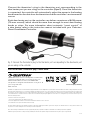
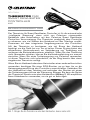
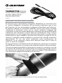
If you are using another manufacturer’s heating band or strip, it needs an
RCA-type plug to connect to the controller’s heater output ports. Connect
the heating band to the telescope and connect its plug to one of the
controller’s dew heater ports. Then, place the tip of the probe thermistor
under the heating band (Figure 1). We suggest using tape to secure it firmly
in place.
THERMISTOR FOR
SMART DEWHEATER
CONTROLLERS
# 94037
INSTRUCTION MANUAL
Fig. 1: Place the thermistor under the heating band so that it is secure.
ENGLISH

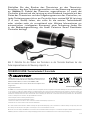
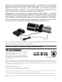
Fig. 2: Connect the thermistor’s plug to the thermistor port corresponding to the dew heater port
you are using on the controller
SPECIFICATIONS: Thermistor plug: 2.5mm Audio
FCC NOTE: This equipment has been tested and found to comply with the limits for a Class B digital device, pursuant to part 15 of the FCC Rules. These limits are designed to provide reasonable
protection against harmful interference in a residential installation. This equipment generates, uses, and can radiate radio frequency energy and, if not installed and used in accordance with
the instructions, may cause harmful interference to radio communications. However, there is no guarantee that interference will not occur in a particular installation. If this equipment does
cause harmful interference to radio or television reception, which can be determined by turning the equipment off and on, the user is encouraged to try to correct the interference by one or
more of the following measures:
• Reorient or relocate the receiving antenna.
• Increase the separation between the equipment and receiver.
• Connect the equipment into an outlet on a circuit different from that to which the receiver is connected.
• Consult the dealer or an experienced radio/TV technician for help.
This device complies with part 15 of the FCC Rules. Operation is subject to the following two conditions: (1) This device may not cause harmful interference, and (2) this device must accept
any interference received, including interference that may cause undesired operation.
Please note that changes or modifications not expressly approved by the party responsible for compliance could void the user’s authority to operate the equipment.
Product design and specifications are subject to change without prior notification. This product is designed and intended for use by those 14 years of age and older.
©2022 Celestron. Celestron and Symbol are trademarks
of Celestron, LLC. All rights reserved. Celestron.com
2835 Columbia Street, Torrance, CA 90503 USA
This product is designed and intended for use by those 14
years of age and older.
Made in China
celestron.com/pages/warranty
Connect the thermistor’s plug to the thermistor port corresponding to the
dew heater port you are using on the controller (Figure 2). Once the thermistor
is connected, the controller will automatically adjust the power to the heating
band based on the data from the thermistor and the controller’s environmental
sensor.
Each dew heater port on the controller can deliver a maximum of 84W power
(7A max current), which should be more than enough for most dew heating
bands or strips. For more information about automatic “smart control” of
a dew heater, refer to the instruction manual included with your Celestron
Smart DewHeater Controller.
11-22

La thermistance pour les contrôleurs Smart DewHeater est requise pour
le «contrôle intelligent» d’un anneau ou d'une bande chauffante par les
contrôleurs Smart DewHeater de Celestron. La thermistance permet
au contrôleur de détecter la quantité de chaleur délivrée par la bande
chauffante au télescope. Avec le capteur environnemental intégré au
contrôleur, la thermistance aide à déterminer de combien de puissance
la bande chauffante doit disposer pour que les optiques restent libres de
rosée. Le système permet l’utilisation de l’énergie la plus efficace pour la
prévention de la rosée, améliorant grandement l’autonomie de la batterie. Si
vous décidez de ne pas utiliser la thermistance, alors vous ne pouvez définir
la puissance de la bande chauffante que manuellement. Si vous utilisez un
Anneau Dew Heater de Celestron, cet assemblage de thermistance n’est
pas obligatoire, car l’anneau en est déjà équipé.
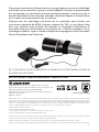
Si vous utilisez une bande ou une languette chauffante de marque autre que
Celestron, elle aura besoin d'une prise de type RCA pour connecter aux
ports de sortie de chauffage du contrôleur. Connectez la bande chauffante
au télescope et connectez sa fiche à l'un des ports du chauffage du
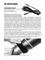
contrôleur anti-buée. Placez ensuite la sonde de la thermistance sous la
bande chauffante (Figure 1). Nous vous suggérons d’utiliser du ruban adhésif
pour la tenir fermement en place.
THERMISTANCE
POUR LES
CONTRÔLEURS
SMART DEWHEATER
# 94037
MODE D'EMPLOI
Fig. 1: Placez la thermistance sous la bande chauffante de manière à la fixer.
FRANÇAIS

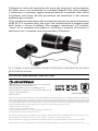
Fig. 2: Connectez la prise de la thermistance correspondante au port du chauffage anti-buée sur
le contrôleur que vous utilisez.
11-22
Remarque relative à la FCC: Cet équipement a été testé et déclaré conforme aux limites d'un appareil numérique de classe B, conformément à la partie 15 des règles de la FCC. Ces limites
sont conçues pour fournir une protection raisonnable contre les interférences nuisibles dans une installation résidentielle. Cet équipement génère, utilise et peut émettre une énergie de
fréquence radio et, s’il n’est pas installé et utilisé conformément aux instructions, peut causer des interférences nuisibles aux communications radio. Mais il n'existe aucune garantie que des
interférences ne seront pas produites dans une installation particulière. Si cet équipement cause des interférences nuisibles à la réception radio ou télévision, ce qui peut être déterminé en
éteignant et en rallumant l'équipement, l'utilisateur est encouragé à essayer de corriger l'interférence par une ou plusieurs des mesures suivantes:
• Réorientez ou déplacez l'antenne de réception.
• Augmentez la distance entre l'équipement et le récepteur.
•Connecter l'équipement dans une prise sur un circuit différent de celui auquel le récepteur est connecté.
• Consultez le revendeur ou un technicien radio / TV expérimenté pour obtenir de l'aide.
Cet appareil respecte la section 15 des règles de la FCC. Son utilisation est sujette aux deux conditions suivantes: (1) Cet appareil ne doit pas causer d'interférences nuisibles et (2) cet appareil
doit accepter toutes les interférences reçues, y compris celles pouvant entraîner un fonctionnement indésirable.
Notez que les changements ou les modifications non expressément approuvée par le fournisseur de cet appareil annule l'autorité de l'utilisateur à utiliser cet appareil.
L'apparence et les caractéristiques techniques du produit sont sujettes à modification sans préavis. Ce produit est conçu et prévu pour être utilisé par des personnes âgées de 14 ans et plus.
©2022 Celestron. Celestron et le Symbol sont des marques
déposées de Celestron, LLC. Tous droits réservés. Celestron.com
2835 Columbia Street, Torrance, CA 90503 USA
Ce produit est conçu et prévu pour être utilisé par des personnes
âgées de 14 ans et plus.
Fabriqué en Chine
celestron.com/pages/warranty
SPÉCIFICATIONS: Fiche de la thermistance: Audio de 2,5mm
Connectez la prise de la thermistance correspondante au port du chauffage
anti-buée sur le contrôleur que vous utilisez (Figure 2). Une fois la thermistance
est connectées, le contrôleur ajustera automatiquement la puissance de la
bande chauffante en fonction des données obtenues depuis la thermistance
et le capteur environnemental du contrôleur.
Chaque port du chauffage anti-buée sur le contrôleur peut fournir une
puissance maximale de 84W (courant maximal de 7A), ce qui devrait être
plus que suffisant pour plupart des bandes ou languettes chauffantes d’
anti-buée. Pour plus d'informations concernant le «contrôle intelligent» d’un
chauffage antibuée, voyez le mode d’emploi accompagnant votre contrôleur
Smart DewHeater de Celestron.

Der Thermistor für Smart DewHeater Controller ist für die automatische
„intelligente Steuerung“ eines nicht von Celestron stammenden
Heizbands oder Heizstreifens mit den Celestron Smart DewHeater
Controllern Voraussetzung. Der Thermistor ermöglicht dem Controller
zu erkennen, wie viel Wärme das Heizband auf das Teleskop ausübt.
Zusammen mit dem integrierten Umgebungssensor des Controllers
hilft der Thermistor zu bestimmen, wie viel Strom das Heizband
benötigt, um die Optik frei von Tau zu halten. Dieses System bietet den
effizientesten Stromverbrauch zur Verhinderung von Taubildung und
verlängert die Batterielebensdauer erheblich. Wenn Sie den Thermistor
nicht verwenden möchten, können Sie die Heizbandleistung nur manuell
einstellen. Wenn Sie einen Tauheizungsring von Celestron verwenden,
ist dieser Thermistor nicht erforderlich, da der Ring bereits über einen
eingebauten Thermistor verfügt.
Wenn Sie ein Heizband oder einen Heizstreifen eines anderen Herstellers
verwenden, benötigen Sie einen RCA-Stecker, um es bzw. ihn an die
Heizausgangsanschlüsse des Controllers anzuschließen. Verbinden Sie
das Heizband mit dem Teleskop und verbinden den Stecker mit einem
der Tauheizungsanschlüsse der Steuerung. Bringen Sie dann die Spitze
der Thermistor-Sonde unter dem Heizband an (Abbildung 1). Wir empfehlen
Ihnen Klebeband zu verwenden, um sie gut zu befestigen.
THERMISTOR FÜR
SMART DEWHEATER
CONTROLLER
#94037
BEDIENUNGSANLEITUNG
Abb. 1: Bringen Sie den Thermistor so unter dem Heizband an, dass er sicher sitzt.
DEUTSCH

Abb. 2: Schließen Sie den Stecker des Thermistors an den Thermistor-Anschluss, der dem
Tauheizungsanschluss an der Steuerung entspricht, an.
FCC-HINWEIS: Dieses Gerät wurde getestet und entspricht den Grenzwerten für digitale Geräte der Klasse B gemäß Teil 15 der FCC-Bestimmungen. Diese Grenzwerte sind so ausgelegt, dass
sie einen angemessenen Schutz gegen schädliche Störungen in einer Wohnanlage bieten. Dieses Gerät erzeugt, verwendet Hochfrequenzenergie und kann diese ausstrahlen und kann, wenn
es nicht in Übereinstimmung mit den Anweisungen installiert und verwendet wird, Störungen im Funkverkehr verursachen. Es kann jedoch nicht garantiert werden, dass in einer bestimmten
Installation keine Störungen auftreten. Wenn dieses Gerät den Radio- oder Fernsehempfang stört, das durch Aus- und Einschalten des Geräts festgestellt werden kann, sollte der Benutzer
versuchen, die Störung durch eine oder mehrere der folgenden Maßnahmen zu beheben:
• Neuausrichtung oder Positionsveränderung der Empfangsantenne.
• Den Abstand zwischen dem Gerät und dem Empfänger vergrößern.
• Schließen Sie das Gerät an eine Steckdose an, die an einem anderen Stromkreis als dem Empfänger angeschlossen ist.
• Den Händler oder einen erfahrenen Radio- und Fernsehtechniker um Hilfe bitten.
Dieses Gerät erfüllt Teil 15 der FCC-Richtlinien. Der Betrieb unterliegt den folgenden beiden Bedingungen: (1) Dieses Gerät darf keine schädlichen Störungen erzeugen und (2) dieses Gerät
muss Störungen von außen akzeptieren, dazu gehören solche Störungen, die einen unerwünschten Betrieb verursachen.
Bitte beachten Sie, dass Änderungen oder Modifikationen an diesem Gerät, die nicht ausdrücklich vom Hersteller zugelassen sind, zum Verlust der allgemeinen Betriebserlaubnis führen können.
Produktdesign und technische Daten können ohne vorherige Ankündigung geändert werden. Dieses Produkt ist für Personen ab 14 Jahren konzipiert und vorgesehen.
©2022 Celestron. Celestron und Symbol sind Warenzeichen
von Celestron, LLC. Alle Rechte vorbehalten. Celestron.com
2835 Columbia Street, Torrance, CA 90503, USA
Dieses Produkt ist für Personen ab 14 Jahren konzipiert und
vorgesehen.
Hergestellt in China celestron.com/pages/warranty
TECHNISCHE DATEN: Thermistorstecker 2,5mm Audio
Schließen Sie den Stecker des Thermistors an den Thermistor-
Anschluss, der dem Tauheizungsanschluss an der Steuerung entspricht,
an. (Abbildung 2). Sobald der Thermistor angeschlossen ist, passt der
Controller automatisch die Leistung an das Heizband, basierend auf den
Daten des Thermistors und des Umgebungssensors des Controllers, an.
Jeder Tauheizungsanschluss am Controller kann maximal 84 W Leistung
(7 A max. Strom) liefern, das sollte für die meisten Tauheizbänder
oder -streifen mehr als ausreichend sein. Weitere Informationen zur
automatischen „intelligenten Steuerung“ einer Tauheizung finden Sie
in der Bedienungsanleitung, die Ihrem Celestron Smart DewHeater
Controller beiliegt.
11-22

Il termistore per comandi smart per sistemi anticondensa è necessario
per un controllo “smart” di una fascia o striscia riscaldante non Celestron
mediante comandi smart per sistemi anticondensa Celestron. Il termistore
consente al comando di rilevare la quantità di calore che la fascia riscaldante
applica al telescopio. Abbinato al sensore ambiente integrato del comando,
il termistore aiuta a stabilire la quantità di potenza richiesta dalla fascia
riscaldante per mantenere le ottiche prive di condensa. Il sistema favorisce
un impiego efficientissimo della potenza per la prevenzione della condensa,
prolungando in maniera significativa la durata della batteria. Se si sceglie
di non utilizzare il termistore, è possibile impostare la potenza della fascia
riscaldante solo manualmente. Se si utilizza un anello riscaldante anti-
rugiada Celestron, non occorre utilizzare questo termistore, poiché l’anello
presenta già un termistore integrato.
Se si utilizza una fascia o striscia riscaldante di un altro produttore,
occorre una spina di tipo RCA per collegarla a una delle porte di uscita del
comando. Collegare la fascia riscaldante al telescopio e collegare la sua
spina a una delle porte del comando anticondensa. Quindi, sistemare la
punta del termistore sotto la fascia riscaldante (Figura 1). Si consiglia di usare
del nastro adesivo per tenerlo fermamente in posizione.
TERMISTORE
PER COMANDI SMART
PER SISTEMI
ANTICONDENSA
N. 94037
MANUALE DI ISTRUZIONI
Fig. 1: Sistemare saldamente il termistore sotto la fascia riscaldante.
ITALIANO

Fig. 2: Collegare la spina del termistore alla porta del termistore corrispondente alla porta che si
sta utilizzando sul comando
SPECIFICHE: Spina termistore: audio da 2,5 mm
NOTA FCC: La presente apparecchiatura è stata testata ed è risultata conforme ai limiti imposti per i dispositivi digitali di Classe B, ai sensi della Parte 15 delle Norme FCC. Tali limiti sono stati
ideati per fornire un’adeguata protezione nei confronti di interferenze dannose in installazioni residenziali. La presente apparecchiatura genera, utilizza e può irradiare energia in radio frequenza
e, se non installata e utilizzata conformemente alle istruzioni, può causare interferenze dannose alle radiocomunicazioni. Tuttavia, non esiste alcuna garanzia che l’interferenza non si verifichi
in una particolare installazione. Nel caso in cui la presente apparecchiatura causi interferenze dannose alla ricezione radio o televisiva, il che potrebbe essere determinato dall'accensione e
dallo spegnimento dell'apparecchiatura, l'utente è incoraggiato a tentare di correggere l'interferenza mediante una o più delle misure seguenti:
• Riorientare o riposizionare l’antenna di ricezione.
• Aumentare la distanza tra l’apparecchiatura e il ricevitore.
• Collegare l’apparecchiatura a una presa su un circuito diverso da quello a cui è collegato il ricevitore.
• Consultare il rivenditore o un tecnico specializzato per ricevere assistenza.
Il presente dispositivo è conforme alla Parte 15 delle Norme FCC. L'utilizzo è soggetto alle seguenti due condizioni: (1) Il presente dispositivo non deve causare interferenze dannose, e (2) il
presente dispositivo deve accettare qualsiasi interferenza ricevuta, comprese interferenze che potrebbero causare un funzionamento indesiderato.
Notare che cambi o modifiche non approvati espressamente dall'ente responsabile della conformità possono annullare l'autorità dell'utente a mettere in funzione l'apparecchiatura.
Il design del prodotto e le specifiche sono soggetti a modifiche senza previa notifica. Questo prodotto è progettato per essere utilizzato da persone di età pari o superiore ai 14 anni.
©2022 Celestron. Celetron e Symbol sono marchi di Celestron,
LLC. Tutti i diritti riservati. Celestron.com
2835 Columbia Street, Torrance, CA 90503 Stati Uniti
Questo prodotto è progettato per essere utilizzato da persone di
età pari o superiore ai 14 anni.
Prodotto in Cina
celestron.com/pages/warranty
Collegare la spina del termistore alla porta del termistore corrispondente
alla porta che si sta utilizzando sul comando (Figura 2). Una volta collegato
il termistore, il comando regola automaticamente la potenza della fascia
riscaldante sulla base dei dati provenienti dal termistore e dal sensore
ambiente del comando.
Ciascuna porta anticondensa del comando può fornire una potenza massima
di 84 W (7 A corrente max), che è più che sufficiente per la maggior parte
delle fasce o strisce riscaldanti. Per maggiori informazioni sul controllo
“smart” di un comando anticondensa, consultare il manuale di istruzioni in
dotazione con il comando smart anticondensa Celestron.
11-22

El termistor para controladores inteligentes DewHeater es necesario para
el "control inteligente" automático de una banda calefactora que no sea
de Celestron con los controladores inteligentes DewHeater de Celestron.
El termistor permite al controlador detectar cuánto calor aplica la banda
calefactora al telescopio. Junto con el sensor ambiental integrado del
controlador, el termistor ayida a determinar la potencia que necesita la banda
calefactora para mantener la óptica libre de condensación. Este sistema
proporciona el uso de energía más eficiente para evitar la condensación,
aumentando en gran medida la duración de la batería. Si elige no usar el
termistor, solamente puede establecer la potencia de la banda calefactora
manualmente. Si usa una anilla calefactora para condensación de
Celestron, no es necesario montar este termistor, dado que la anilla ya
tiene un termistor integrado.
Si usa una banda o tira calefactora de otro fabricante, necesitará un conector
tipo RCA para conectar a los puertos de salida de calefactor del controlador.
Conecte la banda calentadora al telescopio y conecte su conector a uno de
los puertos de calefactor de condensación. A continuación, ponga la punta
del termistor de sonda bajo la banda calefactora (Figura 1). Recomendamos
usar cinta para asegurarla firmemente en posición.
TERMISTOR PARA
CONTROLADORES
INTELIGENTES
DEWHEATER
# 94037
Fig. 1: Ponga el termistor bajo la banda calefactora de forma que quede segura.
MANUAL DE INSTRUCCIONES
ESPAÑOL

Fig. 2: Conecte el conector del termistor al puerto correspondiente de termistor del puerto de
calefactor de condensación que use en el controlador.
NOTA FCC: Este equipo ha sido probado y cumple con los límites de un dispositivo digital de Clase B, según el apartado 15 de las normas FCC. Estos límites están diseñados para proporcionar
una protección razonable contra interferencias dañinas en una instalación doméstica. Este equipo genera, usa e irradia energía de radiofrecuencia y, si no se instala y utiliza de acuerdo con las
instrucciones, puede provocar interferencias dañinas en comunicaciones por radio. Sin embargo, no existe ninguna garantía de que no se produzcan interferencias en una instalación concreta.
Si este equipo causa interferencias dañinas en la recepción de radio o televisión, lo que puede determinarse apagando y encendiendo el equipo, se recomienda al usuario intentar corregir las
interferencias con una o varias de las medidas siguientes:
• Reorientar o recolocar la antena receptora.
• Aumentar la separación entre el equipo y el receptor.
• Conectar el equipo a una toma de un circuito distinto al que esté conectado el receptor.
• Consultar al vendedor o a un técnico experimentado de radio/TV para obtener ayuda.
Este dispositivo cumple con el apartado 15 de las normas FCC. Su uso está sujeto a las dos condiciones siguientes: (1) este dispositivo no puede causar interferencias nocivas, y (2) este
dispositivo debe admitir cualquier interferencia recibida, incluidas las interferencias que puedan causar un funcionamiento indeseado.
Tenga en cuenta que los cambios o modificaciones no aprobadas explícitamente por la parte responsable del cumplimiento pueden anular la autoridad del usuario para usar el equipo.
El diseño y las especificaciones del producto están sujetos a cambios sin notificación previa. Este producto ha sido diseñado y está pensado para ser usado por personas de 14 años o más
de edad.
©2022 Celestron. Celestron y su símbolo son marcas
comerciales de Celestron, LLC. Todos los derechos
reservados. Celestron.com
2835 Columbia Street, Torrance, CA 90503 EE.UU.
Este producto ha sido diseñado y está pensado para
ser usado por personas de 14 años o más de edad.
Fabricado en China
celestron.com/pages/warranty
ESPECIFICACIONES: Conector de termistor: Audio de 2,5mm
Conecte el conector del termistor al puerto correspondiente de termistor
del puerto de calefactor de condensación que use en el controlador
(Figura 2). Cuando el termistor esté conectado, el controlador ajustará
automáticamente la potencia a la banda calefactora basándose en los
datos del termistor y el sensor ambiental del controlador.
Cada puerto de calefactor de condensación puede ofrecer un máximo
de 84W de potencia (corriente máxima de 7A), que debería ser más que
suficiente para la mayoría de bandas o tiras calefactoras de condensación.
Para obtener más información sobre el "control inteligente" automático
de un calefactor de condensación, consulte el manual de instrucciones
incluido con su controlador inteligente DewHeater de Celestron.
11-22
-
 1
1
-
 2
2
-
 3
3
-
 4
4
-
 5
5
-
 6
6
-
 7
7
-
 8
8
-
 9
9
-
 10
10


in anderen Sprachen
- English: Celestron 94037 User manual
- français: Celestron 94037 Manuel utilisateur
- español: Celestron 94037 Manual de usuario
- italiano: Celestron 94037 Manuale utente
Verwandte Artikel
-
Celestron 94038 Benutzerhandbuch
-
Celestron 94256 Benutzerhandbuch
-
Celestron 81038 Bedienungsanleitung
-
-
Celestron Cosmos 90GT WiFi Telescope Benutzerhandbuch
-
-
Celestron COSMOS FirstScope Benutzerhandbuch
-
-
Celestron Cosmos 60AZ Telescope Benutzerhandbuch
-
Celestron 21063 Bedienungsanleitung