Siemens 6EP1933-2EC51-8AA0 Benutzerhandbuch
- Kategorie
- Gefrierschränke
- Typ
- Benutzerhandbuch

© Siemens AG Österreich, AT-1210 Vienna, Austria. All rights reserved. 1 von 8 SITOP UPS 500S
A5E51289135, 12.2021 SITOP UPS 501S
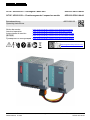
SITOP UPS500S Ex – Grundgerät / basic unit
6EP1933-2EC51-8AA0
SITOP UPS501S Ex – Erweiterungsmodul / expansion module
6EP1935-5PG01-8AA0
Betriebsanleitung A5E51289135
Operating Instructions
Notice de service
https://support.industry.siemens.com/cs/fr/fr/view/31762923
Istruzioni operative
https://support.industry.siemens.com/cs/it/it/view/31762923
Instrucciones de servicio
https://support.industry.siemens.com/cs/es/es/view/31762923
操作说明 https://support.industry.siemens.com/cs/cn/zh/view/31762923
Руководство по эксплуатации
https://support.industry.siemens.com/cs/ru/ru/view/31762923
https://support.industry.siemens.com

© Siemens AG Österreich, AT-1210 Vienna, Austria. All rights reserved. 2 von 8 SITOP UPS 500S
A5E51289135, 12.2021 SITOP UPS 501S
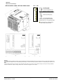
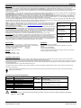
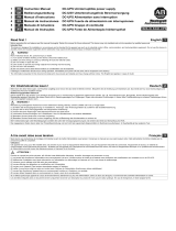
Maßbild
Dimension drawings
6EP1933-2EC51-8AA0 / 6EP1935-5PG01-8AA0 On / Off
Hinweis
Diese Betriebsanleitung enthält aus Gründen der Übersichtlichkeit nicht sämtliche Detailinformationen des Produkts und kann auch nicht jeden denkbaren Fall
der Aufstellung, des Betriebes oder der Instandhaltung berücksichtigen. Technische Änderungen jederzeit vorbehalten. In Zweifelsfällen gilt der deutsche Text.
Note
These operating instructions do not purport to cover all details of the product, nor to provide for every possible contingency that may arise during installation,
operation or maintenance. Subject to change without notice. The German text applies in cases of doubt.
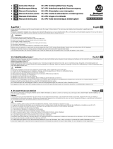
+2V Zuschaltschwelle
+1V (cut-in threshold)
+0,5V +22V fest eingestellt (fixed)
2A / 1A Ladestrom (charging current)
eingestellte Zeit / max. Zeit (set time/max.)
+160s
+ 80s Pufferzeit (buffering time)
+ 40s
+ 20s
+ 10s +5s fest eingestellt (fixed)
Unterbrechung output (disconnection)
Betriebszustand On / Off (operating state)
Grundeinstellung, Auslieferzustand
(basic setting, delivery state)

© Siemens AG Österreich, AT-1210 Vienna, Austria. All rights reserved. 3 von 8 SITOP UPS 500S
A5E51289135, 12.2021 SITOP UPS 501S
1
Deutsch
!
WARNHINWEISE
Nur entsprechend qualifiziertes Fachpersonal darf an diesem Gerät oder in dessen Nähe arbeiten.
Der einwandfreie und sichere Betrieb dieses Gerätes setzt sachgemäßen Transport, fachgerechte Lagerung, Aufstellung, Montage und die
ausschließliche Verwendung von SITOP Kondensator-Modulen voraus.
ACHTUNG
Nur geschultes Personal darf das Gerät öffnen.
Elektrostatisch gefährdete Bauelemente (EGB)
Entsorgungsrichtlinien
Verpackung und Packhilfsmittel sind recyclingfähig und sollten grundsätzlich der Wiederverwertung zugeführt werden.
Das Produkt selbst darf nicht über den Hausmüll entsorgt werden.
Beschreibung und Aufbau
Die DC-USV ist ein Einbaugerät der SITOP -Reihe zur Montage auf Normprofilschiene TH 35-15/7,5 (EN 60715). Für die Installation der Grundgeräte und
Erweiterungsmodule sind die einschlägigen DIN/VDE-Bestimmungen oder länderspezifischen Vorschriften zu beachten.
Es dient zur Pufferung eines Teiles des Laststromes (max. 15A) von 24V-Laststromversorgungen der Reihe SITOP.
Der Eingang "Input L+" des DC-USV-Grundgerätes ist mit dem Ausgang L+ des versorgenden 24V DC-Netzteils zu verbinden, der Eingang "Input M" mit dem
Ausgang M des versorgenden Netzteils. Optional können bis zu 3 Erweiterungsmodule an den Klemmen X10 bzw. X30 angeschlossen werden. Die zu puffernden
Verbraucher werden über den Ausgang „Output L+“ und „Output M“ des DC-USV-Grundgerätes mit der am Eingang angelegten Spannung versorgt, bei Ausfall der
24V DC-Versorgungsspannung bzw. Spannungseinbruch unter die eingestellte Zuschaltschwelle werden die Verbraucher durch Zuschaltung des Erweiterungsmoduls
bzw. der internen Kondensatoren über einen Spannungswandler versorgt.
Über DIP-Schalter können die Zuschaltschwelle, die Ladeleistung und die Überbrückungszeit eingestellt werden. Ein Schalter dient zur Einstellung einer definierten
Überbrückungszeit mit anschließender Abschaltung (siehe Einstellungen), ein Schalter zur Überbrückung des ON/OFF-Kreises, ein Schalter zur Wahl „vor
Abschaltung des Pufferbetriebes Ua für 5s unterbrechen“.
Vier Leuchtdioden, zwei potentialfreie Wechsler, ein Schließer und eine USB-Schnittstelle übernehmen die Signalisierung von Betriebszuständen des DC-USV-
Grundgerätes (siehe Signalisierung) und die Steuerung „Remote-Timerstart“ und „Shutdown“.
Technische Daten
Eingangsgrößen:
Eingangsnennspannung: 24V DC
Arbeitsspannungsbereich: 22 bis 29V DC
max. Eingangsstrom bei 24V und Kondensatorladung: 17,5A DC
max. Eingangsstrom bei 24V und geladenem Kondensator: 15,2A DC
Verlustleistung bei 24V und Kondensatorladung: ca. 11,0W
Verlustleistung 24V und geladenem Kondensator: ca. 9,0W
Ladezeit bei kleiner Ladeleistung und Grundgerät -2EC51- ca. 220s
Ladezeit bei großer Ladeleistung und Grundgerät -2EC51- ca. 120s
Ladezeit bei kleiner Ladeleistung und Grundgerät -2EC51- und einem Erweiterungsmodul
ca. 430s
Ladezeit bei großer Ladeleistung und Grundgerät -2EC51- und einem Erweiterungsmodul
ca. 220s
Ausgangsgrößen:
Ausgangsnennspannung: UA1 = 24V DC
Ausgangsnennstrom: IA1 = 15A DC
Ausgangsstrombereich: IA1 = 0 ... 15A DC
Ausgangskennlinie des Ladereglers:
Die Ladung des Erweiterungsmoduls bzw. der internen Kondensatoren erfolgt mit
einstellbarer Konstantleistung bis zur Ladeschlussspannung.
Ladeschlussspannung: U = 21,8V DC
Ladestrom: IL = 1 oder 2A
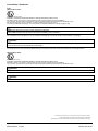
Pufferzeit bei 15A Laststrom mit Grundgerät -2EC51- tp = 9s (typisch)
Pufferzeit bei 15A Laststrom mit Grundgerät -2EC51- und einem Erweiterungsmodul
tp = 20s (typisch)
(siehe Diagramm 1 auf Seite 7)
Einstellungen
Einstellung der Zuschaltschwelle:
Sinkt die Eingangsspannung unter den eingestellten Wert der Zuschaltschwelle, so schaltet das DC-USV-Grundgerät in den Pufferbetrieb um. Die Verbraucher werden
dann ausschließlich durch die DC-USV versorgt. Die Einstellung der Zuschaltschwelle erfolgt mittels 3 Stück DIP-Schalter (Position siehe Seite 2) gemäß Tabelle 1
(siehe Seite 7). Einstellbereich: 22,0 bis 25,5 V DC in 0,5V-Schritten (Auslieferzustand: 22,5V DC ± 0,1V). Genauigkeit: ± 1,8%
Einstellung des Ladestromes:
Die Ladung des Erweiterungsmoduls bzw. der internen Kondensatoren erfolgt mittels Konstantleistung, bis die eingestellte Ladeschlussspannung erreicht ist. Der
Ladevorgang wird dann beendet. Die Einstellung des Ladestromes bestimmt wie schnell die Pufferbereitschaft nach einem Entladevorgang wiederhergestellt ist. Die
Einstellung des Ladestromes erfolgt mittels eines DIP-Schalters (Position siehe Seite 2). Einstellbereich: typ. 1A oder typ. 2A (Auslieferzustand: 1A)
Einstellung des Betriebszustandes ON/OFF:
ACHTUNG: Zur normalen Funktion muss der Betriebszustand unbedingt auf „ON“ eingestellt werden (Auslieferzustand ist „OFF“), dazu DIP-Schalter
auf „ON“ oder X2.9 mit X2.10 verbinden!!
Um eine unbeabsichtigte Entladung der Kondensatoren (z.B. durch Ausschalten der Anlage) zu verhindern, kann das DC-USV-Grundgerät mittels DIP-Schalter (oder
durch Öffnen einer potenzialfreien Verbindung oder Drahtbrücke zw. Klemme X2.9 und X2.10) in den Betriebszustand „OFF“ (Auslieferzustand) geschaltet werden.
Im Betriebszustand „ON“ (DIP-Schalter geschlossen oder Klemme X2.9 mit X2.10 mit potenzialfreiem Schließer für Umax = 15V DC, Imax. = 10mA verbunden oder
X2.9 auf Masse gelegt) bietet das DC-USV-Grundgerät die volle Funktionalität laut Spezifikation. Im Betriebszustand „OFF“ erfolgt bei Wegfall der
Versorgungsspannung keine Umschaltung in den Pufferbetrieb. Alle anderen Funktionen bleiben erhalten. Wird das DC-USV-Grundgerät während des Pufferbetriebes
in den Zustand „OFF“ geschaltet, so wird auch der Pufferbetrieb beendet. Im Normalbetrieb wird die Einstellung ON/OFF alle ca. 20s abgefragt.
Einstellung der Pufferzeit
Die Einstellung der Pufferzeit erfolgt mittels 5 Stück DIP-Schaltern (Position siehe Seite 2) und kann gemäß Tabelle 2 (siehe Seite 7) in 10s-Schritten von 5s bis 315s
vorgenommen werden. Mit Schalter 5 (eingestellte Zeit / max. Zeit) kann gewählt werden, ob die Beendigung des Pufferbetriebes nach der eingestellten Zeit oder erst
bei Erreichen der Tiefentladeschwelle der Kondensatoren (= maximale Pufferzeit) erfolgt. (Auslieferzustand Pos. Off = maximale Pufferzeit). Mit dem Remote-Signal
(wird bei der Schnittstelle beschrieben) kann der Puffertimer gestartet werden, um die USV nach der eingestellten Pufferzeit abzuschalten. Wenn die Abschaltung
erfolgt ist, besteht keine Möglichkeit mittels Änderung der Schaltereinstellung den Pufferbetrieb wieder einzuschalten. Erst nach Wiederkehr der Eingangsspannung
kann ein neuerlicher Pufferbetrieb erfolgen. Bei geladenem DC-USV-Grundgerät und 15A Laststrom beträgt die Pufferzeit ca 3s.
Unterbrechung der Ausgangsspannung
Mittels DIP-Schalter (Position siehe Seite 2) kann gewählt werden, ob die Ausgangsspannung nach Ablauf der eingestellten Pufferzeit für ca. 5 sec unterbrochen wird
oder nicht (Auslieferzustand: Keine Unterbrechung). Bei Einstellung „maximale Pufferzeit“ erfolgt eine Unterbrechung der Ausgangsspannung über das Remote-
Signal der Schnittstelle.
Schutz- und Überwachungsfunktionen
Verpolschutz: Das DC-USV-Grundgerät ist gegen Verpolung der Eingangsspannung elektronisch geschützt.
Überstrom und Kurzschlussschutz: Im Normalbetrieb und im Pufferbetrieb ist das DC-USV-Grundgerät durch die interne dynamische Strombegrenzung und
die interne statische Strombegrenzung geschützt. Die dynamische Strombegrenzung begrenzt den Ausgangsstrom auf typ. 25A. Die statische Strombegrenzung
schaltet den Ausgang bei Strömen größer typ. 18A nach ca. 110ms bei Kurzschluss, sowie nach ca. 200ms bei Überlast ab. Eine eingebaute (nicht zugängliche) 20A -
Sicherung schützt im Fehlerfall. Im Normalbetrieb erfolgen automatische Wiederanlaufversuche alle ca. 20s. Im Pufferbetrieb erfolgt speichernde Abschaltung.
Wiederanlauf erfolgt nach Rückkehr in den Normalbetrieb.

© Siemens AG Österreich, AT-1210 Vienna, Austria. All rights reserved. 4 von 8 SITOP UPS 500S
A5E51289135, 12.2021 SITOP UPS 501S
Deutsch
Signalisierung
„Normalbetrieb“, d.h. die Eingangsspannung am DC-USV-Grundgerät ist höher als die eingestellte Zuschaltschwelle. Die Verbraucher werden von der
vorgeschalteten Stromversorgung versorgt. Falls ein Erweiterungsmodul angeschlossen ist, wird dieses geladen. Im Normalbetrieb leuchtet die grüne Leuchtdiode
(o.k.) und der Relaiskontakt X2.2 – X2.3 (o.k.) ist geschlossen.
„>85% Vollladung“, d.h. Kondensatorladung größer 85%. Es wird ausschließlich das Grundgerät überwacht. Es leuchtet die zweite grüne Leuchtdiode
(Bat>85%) und der Relaiskontakt X2.7 – X2.8 ist geschlossen. (zweite grüne Leuchtdiode aus und Relaiskontakt X2.7 – X2.8 offen (Ruhestellung bei abgeschaltetem
Gerät) bedeutet : Bat<85%, d.h. Kondensatorladung unter 85%)
„Pufferbetrieb“, d.h. die Eingangsspannung ist niedriger als die eingestellte Zuschaltschwelle. Die Verbraucher werden von der DC-USV versorgt. Im Pufferbetrieb
leuchtet die gelbe Leuchtdiode (Bat) und der Relaiskontakt X2.1 – X2.2 (Bat) ist geschlossen (Ruhestellung bei abgeschaltetem Gerät).
Alarmmeldung “Pufferbereitschaft fehlt“: Bei Signal „Pufferbereitschaft fehlt“ leuchtet die rote Leuchtdiode (Alarm) und der Relaiskontakt X2.4 – X2.5 (Alarm) ist
geschlossen (Ruhestellung bei abgeschaltetem Gerät). Ursachen für eine fehlende Pufferbereitschaft im Normalbetrieb können sein:
Betriebszustand OFF, defekter Kondensator bzw. Kondensatorspannung < 7V. Es wird ausschließlich das Grundgerät überwacht.
Die Abfrage von Betriebszustand ON/OFF, Kondensator bzw. Kondensatorspannung < 7V und somit auch die Ausgabe des Signals erfolgt im Normalbetrieb alle 20s.
Nach Fehlerende erfolgt die Rücksetzung nach der nächsten Abfrage.
Im Pufferbetrieb bedeutet das Signal „Alarm“, dass die Kondensatorspannung auf <12V gesunken ist und eine Zwangsabschaltung unmittelbar bevor steht. Nach
Abschaltung des Pufferbetriebes aufgrund Überlast, Kurzschluss, Entladung oder abgelaufener Pufferzeit erlischt die rote Leuchtdiode (Alarm), der Relaiskontakt X2.4
– X2.5 bleibt geschlossen. Belastbarkeit der Relaiskontakte (SELV (ES1) ist einzuhalten): DC 30 V/1 A.
USB: Die Signale werden zusätzlich über eine PC-fähige USB-Schnittstelle ausgegeben. Die Signale werden mit
einem jeweils 5 Zeichen langen String ausgegeben. Es gilt die nebenstehende Tabelle. Ein Softwaretool zum Auslesen
und Verarbeiten der Signale steht im Internet unter http://www.siemens.de/sitop-usv kostenlos zur Verfügung. Hier sind
auch weitere Informationen zur Schnittstelle angeführt.
Technische Ausführung: Die USB Schnittstelle entspricht der Spezifikation 2.0. Die Kommunikation erfolgt aber nur mit
Full Speed, d.h. 12Mbit/s, die USB-Optionsbaugruppe wird von der DC-USV mit +5V versorgt („self powered“),
Ausgabe der Signalzustände alle 75ms ± 20%; 29ms ± 20% Datenausgabe; 46ms ± 20% Pause. Die Verbindung zum
PC erfolgt über ein handelsübliches 4-adriges, geschirmtes USB-Kabel mit einem Wellenwiderstand von 90Ohm, einem
USB Series „A“ Stecker zum PC und einem USB Series „B“ Stecker zur DC-USV und einer maximalen Länge von 5m.
Das Kabel besteht aus zwei 28 bis 20 AWG „non-twisted“ USB-Versorgungsleitungen (VBUS und GND) und aus zwei
28 AWG „twisted pair“ Datenleitungen (D+ und D-).
Steckerbelegung: Pin 1: VBUS (+4,40V ... +5,25V DC), Sendedaten auf Pin2 (D-) und Pin 3 (D+), Pin 4: GND.
Empfangsdaten: Der Empfang des Zeichens „R“ (Signal Remote Timerstart) startet den Timer im DC-USV-Grundgerät
mit der dort eingestellten Überbrückungszeit (Tabelle 2). Nach der eingestellten Überbrückungszeit wird der
Pufferbetrieb beendet bzw. im Normalbetrieb die Ausgangsspannung bei Einstellung „Unterbrechung“ für 5s
unterbrochen. Der Empfang des Zeichens „S“ (Signal Shutdown) startet den Timer im DC-USV-Grundgerät mit der dort
eingestellten Überbrückungszeit (Tabelle 2). Nach der eingestellten Überbrückungszeit wird das DC-USV-Grundgerät
speichernd abgeschaltet. Ein Wiederanlauf erfolgt durch Unterbrechung der DC-Versorgungsspannung für min. 1s. In
Kombination mit einer SITOP Power Supply muss für einen Wiederanlauf die Netzspannung für ca 10s unterbrochen
werden.
Signal
Klartext
Pufferbereitschaft vorhanden
Pufferbereitschaft fehlt
BUFRD
ALARM
Normalbetrieb
kein Normalbetrieb
DC_OK
DC_LO
kein Pufferbetrieb
Pufferbetrieb
*****
*BAT*
≥
85% Vollladung
≤ 85% Vollladung
BA>85
BA<85
Umgebung
Einsatzbedingungen nach EN 60721-3-3, Klimaklasse 3K3 (relative Luftfeuchte
5% bis 85% und absolute Luftfeuchte 1 g/m³ bis 25 g/m³; keine Betauung).
Ortsfester Einsatz, wettergeschützt, Verschmutzungsgrad 2
Temperatur für Lagerung und Transport: -40 bis +70°C
Temperatur für Betrieb: 0 bis +60°C
Überspannungskategorie: II bis 2000 m
Gewicht
6EP1933-2EC51-8AA0 1,2kg
6EP1935-5PG01-8AA0 0,7kg
Vorschriften
Schutzart: IP20 nach EN60529
Schutzklasse III, ausgelegt zum Anschluss an geregelte
24 V DC-Stromversorgungen
UL 508 / CSA C22.2 File E197259
Das Gerät erfüllt die ATEX Richtlinie 2014/34/EU; EN 60079-0; EN 60079-7
ATEX (siehe Seite 8), DNV GL und ABS
Montagehinweise
Das Gerät ist zwecks ordnungsgemäßer Entwärmung vertikal so zu montieren, dass die Eingangsklemmen, die Ausgangsklemmen und Zuluftschlitze unten sind.
Unterhalb und oberhalb des Gerätes soll mindestens ein Freiraum von je 50mm eingehalten werden.
Um Störeinkopplungen und thermische Beanspruchung zu minimieren, sollen DC-USV-Grundgeräte und zugehörige Erweiterungsmodule mindestens 50 cm entfernt
von Kommutierungsdrosseln installiert werden! Schnittstellen- (USB) und Steuerleitungen (ON/OFF-Steuerstromkreis) dürfen nicht direkt parallel zu
Leistungsleitungen (insbesondere Leitungen zwischen Frequenzumrichter und Motor sowie Frequenzumrichter und Kommutierungsdrossel) verlegt werden. Um
Störeinkopplungen zu minimieren soll zu diesen Leitungen ein Abstand von mindestens 10cm eingehalten werden.
Bei Installation des Gerätes in explosionsgefährdeter Umgebung ist dieses in einen Verteilerkasten mit Schutzart IP54 oder höher einzubauen. Dieser Verteilerkasten
muss den Anforderungen der EN 60079-0 entsprechen.
Vor Beginn der Installations oder Instandhaltungsarbeiten ist der Hauptschalter der Anlage auszuschalten und gegen Wiedereinschalten zu sichern. Es ist
die Betriebsanleitung von SITOP power zu beachten.
Anschluss und Klemmenbelegung
Klemmen
Funktion
Anschlusswert
Bemerkung
X1.1
Eingangsspannung DC 24V
1,0 ... 4mm2
Schraubklemmen für Schraubendreher mit
X1.3, X1.5
Ausgangsspannung DC 24V
17...11 AWG
4,5mm Klingenbreite
X1.2/X1.4, X1.6
Ein/Ausgangsspannung DC 0V
empfohlenes Anzugsmoment 0,7-0,9Nm
X2.1,2,3
Signal: Normalbetrieb / Pufferbetrieb
0,5... 2,5mm2
Schraubklemmen für Schraubendreher mit
X2.4,5,6
Signal: Pufferbereitschaft fehlt / vorhanden
20...13 AWG
3,5mm Klingenbreite
X2.7,8
Signal: Ladezustand >85%
X2.9/X2.10
On/Off – Brücke (keine Brücke =Off)
empfohlenes Anzugsmoment 0,5-0,7Nm
X3
USB-Schnittstelle
Siehe Beschreibung oben
X10
Kondensator-Modul
Konfektionierter Kabelsatz
Verwenden sie Kupferdraht zugelassen für 60/75 °C.
!
ACHTUNG
Die externe Beschaltung aller Klemmen (auch Signal- und Meldekontakte) muss den Anforderungen an SELV (ES1)-Kreise
nach EN61204-7 genügen.

© Siemens AG Österreich, AT-1210 Vienna, Austria. All rights reserved. 5 von 8 SITOP UPS 500S
A5E51289135, 12.2021 SITOP UPS 501S
English
!
WARNINGS
Only properly qualified personnel may work on or around this equipment.
The successful and safe operation of this equipment is dependent on proper handling, storage and installation. Correct functioning is also
dependent on the use of SITOP ultra modules
CAUTION
Only trained personnel may open the unit. Electrostatically sensitive devices (ESD)
Disposal Guideline
Packaging and packing aids can be recycled and should always be disposed of for reuse.
The product itself shall not be disposed of as normal domestic waste.
Description and Design
The DC-UPS is a chassis unit in the SITOP power product range for mounting on a DIN rail of type TH 35-15/7,5 (EN 60715).
The basic units and the expansion modules must be installed in accordance with the applicable DIN/VDE specifications or pertinent regulations in the country of
installation.
It buffers a proportion of the load current (max. 15A) of 24V load current supplies in the SITOP range.
Input "Input L+" on the DC-UPS basic units must be connected to output L+ of the 24V DC power supply unit and input "Input M" to output M of the power supply unit.
It is possible to connect max. 3 expansion modules via the connectors X10 and X30. The loads to be buffered are supplied via outputs "Output L+" and "Output M" on
the DC-UPS basic unit with the voltage connected to the input. If the 24V DC supply voltage fails or drops below the set cut-in threshold, the expansion module or the
internal capacitors are connected in to supply the loads.
The cut-in threshold, charging power and the buffering time can be set via DIP-switches. A switch is provided for setting a defined buffering (stored energy) time with
subsequent disconnection (see Settings), one switch for bridging the ON/OFF circuit, one switch for choosing if the output voltage is interrupted for 5 s at the end of the
buffering time or not.
The operating states of the DC-UPS basic unit are signaled by four LEDs, two floating changeover and one normally-open contacts and a USB-interface (see
Signaling) and the control signal “Remote Timerstart” and “Shutdown”.
Technical Data
Input quantities:
Rated input voltage: 24V DC
Operating voltage range: 22 to 29V DC
Max. input current at 24V and capacitor charging: 17.5A DC
Max. input current at 24V and charged capacitors: 15.2A DC
Power loss at 24V and capacitor charging: appr. 11.0W
Power loss at 24V and charged capacitors: appr. 9.0W
Charging time with low charging power and basic unit -2EC51-: appr. 220s
Charging time with high charging power and basic unit -2EC51-: appr. 120s
Charging time with low charging power and basic unit -2EC51- and one expansion module:
appr. 430s
Charging time with high charging power and basic unit -2EC51- and one expansion module:
appr. 220s
Output quantities:
Rated output DC voltage: VA1 = 24V DC
Rated output direct current: IA1 = 15A DC
Output current range: IA1 = 0 … 15A DC
Output characteristic of charging regulator:
The capacitors are charged at an adjustable constant power until the
end-of-charge voltage is reached.
End-of-charge voltage: V = 21.8V DC
Charging current: P = 1 or 2A
Buffering time at 15A load current with basic unit -2EC51-: tp = 9s (typ.)
Buffering time at 15A load current with basic unit -2EC51- and one add-
on expansion module: tp = 20s (typ.)
(see diagram 1 on page 7)
Settings
Setting the cut-in threshold:
If the input voltage drops below the selected cut-in threshold voltage, the DC-UPS basic unit switches over to floating operation. The loads are then supplied solely by
the DC UPS. The cut-in threshold is set via three DIP-switches (see page 2 for position) according to table 1 (see page 7).
Setting range: 22.0 to 25.5V DC in 0.5-steps (delivery state: 22.5V DC ± 0.1V), accuracy ± 1.8%
Setting the charging current:
The expansion module or the internal capacitors are charged via constant current until the set end-of-charge voltage is reached. Charging is then terminated. The
setting of the charging current determines how quickly the buffer ready state is restored after a discharging process. The charging current is set by a DIP switch
(position see page 2). Setting range: typ. 1A or typ. 2A (delivery state: 1A)
Setting the operating state ON/OFF:
Caution: For normal operation "ON" state is necessary (delivery state is “OFF”), in order to achieve that use DIP-switch closed or terminals X2.8 and
X2.9 connected with X2.10
To prevent the capacitors from being discharged unintentionally (e.g. when the system power is disconnected), the DC-UPS basic unit can be switched with a DIP-
switch (or a wire jumper (or floating connection) inserted between terminals X2.9 and X2.10) to operating state "OFF" (delivery state). In the "ON" state (DIP-switch
closed or terminals X2.8 and X2.9 connected with a floating normally-open contact (Vmax = 15V DC, Imax = 10mA) ), the DC-UPS basic unit is fully functional according
to specification. In the "OFF" state, the module does not switch over to floating operation when the mains supply is disconnected but remains functional in every other
respect. If the DC-UPS basic unit is switched to "OFF" in floating operation, it stops operating in floating mode.
During normal operation, the polling interval for the ON/OFF setting is appr. 20s.
Setting the buffering time:
The buffering time is set via five DIP-switches (see page 2 for position) as illustrated in Table 2 (see page 7) in 10s-steps from 5s to 315s. By switch 5 (delivery state
max. time) you can choose whether floating operation will be terminated after a prespecified period or when the exhaustive discharge threshold of the capacitors (=
maximum buffering time) is reached (delivery state: max. buffering time). Using the remote signal starts the timer to terminate after a prespecified period. Once the
buffering has been terminated, there is no way in which floating operation can be restarted again by altering the switch setting. Only when the input voltage has
recovered floating operation can be resumed. The buffering time is a appr. 3s with fully charged capacitors and a load current of 15A.
Interruption of the output voltage:
By a DIP-switch (see page 2 for position) you can choose if the output voltage is interrupted for 5 s at the end of the buffering time or not (delivery state : no
interruption). Using the setting “max. time” an interruption is started by the remote signal.
Protective and Monitoring Functions
Reverse polarity protection: The DC-UPS basic unit is electronically protected against polarity reversal of the input voltage.
Overcurrent and short-circuit protection: In normal operation and floating operation the DC-UPS basic unit is protected by the internal dynamic current
limitation and the internal static current limitation. Dynamic current limitation limits the output current to typ. 25A. Static dynamic limitation shuts down the output if
currents are greater than typ. 18A after about 110ms at short-circuit, and after about 200ms at overload. An internal (not accessible) 20A fuse protects the module in
the event of a fault. In normal operation automatic restart attempts are made approximately every 20s. In floating operation the module shuts down in store mode.
Restart after return to normal operation.

© Siemens AG Österreich, AT-1210 Vienna, Austria. All rights reserved. 6 von 8 SITOP UPS 500S
A5E51289135, 12.2021 SITOP UPS 501S
English
Signaling
"Normal operation", i.e. the input voltage at the DC-UPS basic unit is higher than the set cut-in threshold. The loads are being fed by the line-side power supply. If a
expansion module is connected, it is fully charged. Under normal operation, the green LED (o.k.) is illuminated and relay contact X2.2 – X2.3 (o.k.) is closed.
“>85% charge”, i.e. capacitor is loaded more than 85% (available rest capacity dependent upon aging). The second green LED (Bat>85%) is illuminated and relay
contact X2.7 – X2.8 is closed. (second green LED off and relay contact X2.7 – X2.8 open (de-energized position when unit is disconnected) means : Bat<85%, i.e.
capacitor charge below 85%)
"Floating operation", i.e. the input voltage is lower than the set cut-in threshold. The loads are being supplied by the DC-UPS. In floating operation, the yellow LED
(Bat) is illuminated and relay contact X2.1 – X2.2 (Bat) closed (de-energized position when unit is disconnected).
Alarm signal "Buffering not ready": When the "Buffering not ready" signal is active, the red LED (Alarm) is illuminated and relay contact X2.4 – X2.5 (Alarm) closed
(de-energized position when unit is disconnected). Causes for the "Buffering not ready" state in normal operation are as follows: "OFF" operating state, defective
capacitors or capacitor voltage < 7V. The interval for polling the operating states ON/OFF, capacitors or capacitor voltage < 7V, and for activating the relevant signal
output is 20 s during normal operation. After the end of the failure the signal remains till to the next polling.
The "Alarm" signal in floating operation means that the capacitor voltage has dropped to <12V and automatic disconnection is imminent. When the floating operation
has been finished due to overload, short circuit, exhaustive discharge protection or buffering timeout, the red LED (Alarm) gets dark, but relay contact X2.4 – X2.5
remains closed. Load rating of relay contacts (SELV (ES1) must be maintained): 30 V DC/1 A.
USB:
The signals are additionally outputs via a PC-capable USB interface. They are each displayed in the shape of 5
characters of plain text. The assignment is shown in the table on the right. A tool for reading out and processing the
signals is available free of charge on the Internet at http://www.siemens.com/sitop-ups. This website also contains
further information about the interface.
Technical specification: The USB interface is according to specification 2.0, the communication runs only at full speed,
i.e. 12Mbit/s. The Interface will be supplied by the DC-UPS with +5V (“self-powered”), signal state output every 75ms ±
20%; data output 29ms ± 20%, pause 46ms ± 20%. The connection to the PC is made by means of a usual 4-wired
shielded USB-cable with a wave-resistance of 90Ohm, a USB Series”A” connector to the PC and a USB Series “B”
connector to the DC-UPS and a maximum length of 5m. The cable contains two 28 to 20 AWG “non-twisted” USB-
supply wires (VBUS and GND) and two 28 AWG “twisted pair” data wires (D+ and D-).
Pin assignment: Pin1: VBUS (+4.4V to +5.25V DC), transmit data on Pin2 (D-) and Pin3 (D+), Pin4: GND
Receiving data: Receive of the character “R” (Signal Remote Timerstart) starts the timer of the DC-UPS basic unit with
the set buffering time (table 2). After the set buffering time, floating operation ends or, during normal operation, the
output voltage is interrupted for 5 s if "disconnection" is set. Receipt of the character "S" (shutdown signal) starts the
timer in the DC-UPS basic unit with the set buffering time (table 2). After the set buffering time the DC-UPS basic unit is
switched off retentively. It is restarted by disconnecting the DC supply voltage for at least 1 s. In combination with a
SITOP power supply the line voltage has to be interrupted for approx. 10 s for a restart.
Signal
Text
Buffering ready
Buffering not ready
BUFRD
ALARM
Normal operation
Not normal operation
DC_OK
DC_LO
Not floating operation
Floating operation
*****
*BAT*
>85% charge
<85% charge
BA>85
BA<85
Environment
Operating conditions acc. to EN 60721-3-3, climate model 3K3 (relative air
humidity 5% to 85%, absolute air humidity 1 g/m3 to 25 g/m3, no condensation)
Stationary operation, weather protected, pollution degree 2
Temperature for storage and shipment: -40 to +70°C
Temperature for operation: 0 to +60°C
Overvoltage category: II to 2000 m
Weight
6EP1933-2EC51-8AA0 1.2kg
6EP1935-5PG01-8AA0 0.7kg
Standards
Degree of protection: IP20 to EN60529
Protection class III, designed to be connected to regulated 24 V DC power
supplies
Protection class III to EN60950
UL 508 / CSA C22.2 File E197259
The device complies with ATEX directive 2014/34/EU; EN 60079-0; EN 60079-7
ATEX (see page 8), DNV GL and ABS
Installation Instructions
In order to guarantee effective cooling, the unit must be vertically installed such that the input and output terminals and the incoming air slots are at the bottom. A
clearance of at least 50 mm must be left above and below the unit. Assembly / disassembly see page 8.
To reduce EMI and thermal strain DC-UPS and capacitor modules should be installed at least 50cm away from commutating chokes! Interface (USB) and control leads
(ON/OFF control circuit) must not be laid directly in parallel to power leads or cables (especially leads between frequency converter and motor or frequency converter
and commutating choke).
To minimize EMI the distance to those leads should be at least 10cm.
If the device is to be used in a hazardous zone it must be installed in an enclosure with degree of protection IP54 or higher. This enclosure must comply with the
requirements of EN 60079-0.
Before commencing with the installation or any repair work, switch off the plant main switch and lock it in the "OFF" position. Please read the operating
instructions for SITOP power.
Connection and Terminal Assignments
Terminals
Function
Cable cross-
section
Comments
X1.1
Input voltage DC 24V
1.0 ... 4mm2
Screw-type terminals for screwdriver with
X1.3, X1.5
Output voltage DC 24V
17...11 AWG
4.5mm blade width
X1.2/X1.4, X1.6
Input/output voltage DC 0V
Recommended tightening torque 0.7-0.9Nm
X2.1,2,3
Signal: Normal operation / Floating operation
0.5... 2.5mm2
Screw-type terminals for screwdriver with
X2.4,5,6
Signal: Buffering not ready / ready
20...13 AWG
3.5mm blade width
X2.7,8
Signal: charge >85%
X2.9/X2.10
On/Off jumper (no jumper =Off)
Recommended tightening torque 0.5-0.7Nm
X3
Serial interface or USB-interface
See description above
X10
Capacitor module
Tailored wire set
Use copper wire approved for 60/75 °C.
!
CAUTION
The external circuitry of all terminals (including signaling and status contacts) must meet the safety requirements stipulated by
EN61204-7: SELV (ES1).

© Siemens AG Österreich, AT-1210 Vienna, Austria. All rights reserved. 7 von 8 SITOP UPS 500S
A5E51289135, 12.2021 SITOP UPS 501S
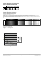
Tabelle 1: Einstellbare Zuschaltschwellen
Table 1: Adjustable cut-in threshold
On←1
2
3
gewünschte Zuschaltschwelle [V]
22,0
22,5
23,0
23,5
24,0
24,5
25,0
25,5
0
0
0
0
1
1
1
1
0
0
1
1
0
0
1
1
0
1
0
1
0
1
0
1
Tabelle 2: Einstellbare Pufferzeiten
Table 2: Adjustable buffering time
Schalterstellung / Switch position: On = 1 ; Off = 0
Schalter 1 auf Pos. On: Einstellung um nach der gewünschten Pufferzeit abzuschalten (setting to terminate after the prespecified buffering time)
Schalter 1 auf Pos. Off: Die Abschaltung erfolgt erst bei Erreichen der Tiefentladeschwelle des Kondensatoren. Im Remote-Betrieb kann nach der eingestellten
Pufferzeit die Spannung unterbrochen werden (DIP-Schalter Unterbrechung – On)
Setting to terminate when the exhaustive discharge threshold of the capacitors is reached. An interruption is started by the remote signal. (DIP-switch Disconnection –
On)
On ←
6
7
8
9
10
gewünschte Pufferzeit / buffering time [s]
5
15
25
35
45
55
65
75
85
95
105
115
125
135
145
155
165
175
185
195
205
215
225
235
245
255
265
275
285
295
305
315
0
0
0
0
0
0
0
0
0
0
0
0
0
0
0
0
1
1
1
1
1
1
1
1
1
1
1
1
1
1
1
1
0
0
0
0
0
0
0
0
1
1
1
1
1
1
1
1
0
0
0
0
0
0
0
0
1
1
1
1
1
1
1
1
0
0
0
0
1
1
1
1
0
0
0
0
1
1
1
1
0
0
0
0
1
1
1
1
0
0
0
0
1
1
1
1
0
0
1
1
0
0
1
1
0
0
1
1
0
0
1
1
0
0
1
1
0
0
1
1
0
0
1
1
0
0
1
1
0
1
0
1
0
1
0
1
0
1
0
1
0
1
0
1
0
1
0
1
0
1
0
1
0
1
0
1
0
1
0
1
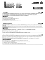
Diagramm 1: Pufferzeit
Diagram 1: buffering time
0
50
100
150
200
250
300
2,5 57,5 10 12,5 15
I [ A]
t [sec]
Basic module
6EP1933-2EC51
plus 1 capacitor
module
plus 2 capacitor
modules
plus 3 capacitor
modules

© Siemens AG Österreich, AT-1210 Vienna, Austria. All rights reserved. 8 von 8 SITOP UPS 500S
A5E51289135, 12.2021 SITOP UPS 501S
Vorschriften / Standards:
ATEX
6EP1933-2EC51-8AA0:
II 3G Ex ec nC IIC T4 Gc
WARNING: SEPARATE EXPANSION MODULE IN NON-HAZARDOUS AREAS ONLY!
Harzardous Areas: An enclosure / cabinet rated min. IP54 must be provided in the final installation.
The enclosure / cabinet must be in accordance with the requirement of EN 60079-0:2009 and/or EN60079-7:2010
DIP switches shall not be used in operation or while a hazardous area may be present
Only locking USB-cable type (Partno: Y-Con IP20LOCK-104 cable assy Distributor: Yamaichi) shall be used
WARNUNG
ANSCHLÜSSE NUR IN NICHT-EXPLOSIVER UMGEBUNG TRENNEN!
SCHALTERBETÄTIGUNG NUR IN NICHT-EXPLOSIVER UMGEBUNG DURCHFÜHREN!
Der Signalstecker darf in Ex Bereichen nur mit zusätzlichen Befestigungen verwendet werden um der EN 60079-7 zu genügen.
WARNING
SEPARATE TERMINALS IN NON-HAZARDOUS AREAL ONLY!
ACTUATE SWITCHES IN NON-HAZARDOUS AREAS ONLY!
The signal plug must not be used without additional fixings in explosive atmospheres to fulfill the requirements according EN 60079-7.
6EP1935-5PG01-8AA0:
II 3G Ex ec IIC T4 Gc
WARNING: SEPARATE EXPANSION MODULE IN NON-HAZARDOUS AREAS ONLY!
Harzardous Areas: An enclosure / cabinet rated min. IP54 must be provided in the final installation.
The enclosure / cabinet must be in accordance with the requirement of EN 60079-0:2009 and/or EN60079-7:2010
WARNUNG
ANSCHLÜSSE NUR IN NICHT-EXPLOSIVER UMGEBUNG TRENNEN!
WARNING
SEPARATE TERMINALS IN NON-HAZARDOUS AREAL ONLY!
© Siemens AG Österreich, AT-1210 Vienna, Austria. All rights reserved.
Liefermöglichkeiten und technische Änderungen vorbehalten
Availability and technical specifications subject to change without prior notice
-
 1
1
-
 2
2
-
 3
3
-
 4
4
-
 5
5
-
 6
6
-
 7
7
-
 8
8


Siemens 6EP1933-2EC51-8AA0 Benutzerhandbuch
- Kategorie
- Gefrierschränke
- Typ
- Benutzerhandbuch
in anderen Sprachen
Andere Dokumente
-
 Rockwell Automation 1606-XLS240-UPS Benutzerhandbuch
-
WAGO epsitron 787-870 Benutzerhandbuch
-
 Rockwell Automation 1606-XLS240-UPSC Benutzerhandbuch
-
 Rockwell Automation 1606-XLSBUFFER24 Benutzerhandbuch
-
STIEBEL ELTRON WPIC Operation Instruction
-
Danfoss ICAD-UPS for ICM 20 ICM 125 Installationsanleitung
-
-
-
Buhler TC-MINI Brief Instructions
-
Lenze CPC 9100 Operating Instructions Manual


