Seite wird geladen ...

1 EN Instruction Manual Buffer Module
2
DE Bedienungsanleitung Puffermodul
3 FR Manual d'instructions Module tampon
4 ES Manual de instrucciones Módulo búfer
5 IT Manuale di Istruzione Modulo tampone
6 PT Manual de Instruções Módulo- tampão
1606-XLSBUFFER24
1606-XLSBUFFER48
Read this first! English 1
Before operating this unit please read this manual thoroughly and retain this manual for future reference! This device may only be installed and put into operation by qualified personnel. If damage or
malfunction should occur during operation, immediately turn power off and send unit to the factory for inspection. The unit does not contain serviceable parts.
The information presented in this document is believed to be accurate and reliable and may change without notice. For any clarifications the English translation will be used.
Intended Use: This device is designed for installation in an enclosure and is intended for the general use such as in industrial control, office, communication, and instrumentation equipment. Do not
use this device in aircrafts, trains and nuclear equipment where malfunction may cause severe personal injury or threaten human life.
WARNING
Risk of electrical shock, fire, personal injury or death.
1) Turn power off before working on the device. Protect against inadvertent re-powering.
2) Make sure that the wiring is correct by following all local and national codes.
4) Do not modify or repair the unit.
4) Do not open the unit as high voltages are present inside.
5) Use caution to prevent any foreign objects from entering into the housing.
6) Do not use in wet locations or in areas where moisture or condensation can be expected.
Vor Inbetriebnahme lesen! Deutsch 2
Bitte lesen Sie diese Warnungen und Hinweise sorgfältig durch, bevor Sie das Gerät in Betrieb nehmen. Bewahren Sie die Anleitung zum Nachlesen auf. Das Gerät darf nur durch fachkundiges und
qualifiziertes Personal installiert werden. Bei Funktionsstörungen oder Beschädigungen schalten Sie sofort die Versorgungsspannung ab und senden das Gerät zur Überprüfung ins Werk. Das Gerät
beinhaltet keine Servicebauteile. Die angegebenen Daten dienen allein der Produktbeschreibung und sind nicht als zugesicherte Eigenschaften im Rechtssinne aufzufassen. Im Zweifelsfall gilt der
englische Text.
Bestimmungsgemäßer Gebrauch: Dieses Gerät ist für den Einbau in ein Gehäuse konzipiert und zur Verwendung für allgemeine elektronische Geräte, wie z.B. Industriesteuerungen, Bürogeräte,
Kommunikationsgeräte oder Messgeräte geeignet. Benutzen Sie dieses Gerät nicht in Steuerungsanlagen von Flugzeugen, Zügen oder nuklearen Einrichtungen, in denen eine Funktionsstörung zu
schweren Verletzungen führen oder Lebensgefahr bedeuten kann.
WARNUNG
Missachtung nachfolgender Punkte kann einen elektrischen Schlag, Brände, schwere Unfälle oder Tod zur Folge haben.
1) Schalten Sie die Eingangsspannung vor Installations-, Wartungs- oder Änderungsarbeiten ab und sichern Sie diese gegen unbeabsichtigtes Wiedereinschalten.
2) Sorgen Sie für eine ordnungsgemäße und fachgerechte Verdrahtung.
3) Führen Sie keine Änderungen oder Reparaturversuche am Gerät durch.
4) Gerät niemals öffnen. Im Inneren befinden sich gefährliche Spannungen.
5) Verhindern Sie das Eindringen von Fremdkörpern, wie z.B. Büroklammern und Metallteilen.
6) Betreiben Sie das Gerät nicht in feuchter Umgebung oder in einer Umgebung, bei der mit Betauung oder Kondensation zu rechnen ist.
A lire avant mise sous tension! Français 3
Merci de lire ces instructions de montage et d'entretien avant de mettre l'alimentation sous tension. Conservez ce manuel qui vous sera toujours utile. Cette alimentation doit être installée par du
personnel qualifié et compétent. Le déclenchement du fusible interne traduit très probablement un défaut au niveau de l'appareil. Si un défaut quelconque apparaît en cours de fonctionnement,
débrancher au plus vite l'alimentation. Dans ce deux cas de figure, il convient de faire contrôler l'alimentation en usine! Les données indiquées dans ce document servent uniquement à donner une
description du produit et n'ont aucune valeur juridique. En cas de divergences, le texte anglais fait foi.
Utilisation: Cet appareil est conçu pour être installé dans une armoire et pour tous les équipements électroniques, tel que l'équipement industriel de commande, l'équipement de bureau, le matériel
de communication et les instruments de mesures. N'utilisez pas cet appareil pour l'équipement de commandes dans les avions, les trains et l'équipement atomique où un problème de
fonctionnement de l'alimentation pourrait causer des blessures graves ou menacer la vie humaine.
AVERTISSEMENT
Prendre en compte les points suivants, afin d'éviter toute détérioration électrique, incendie, dommage aux personnes ou mort.
1) débrancher l'installation avant toute intervention sur l'alimentation (ou démontage) et s'assurer qu'il n'y a pas risque de redémarrage.
2) s'assurer que le câblage a été fait selon les prescriptions
3) ne pas effectuer de réparations ou modifications sur l'alimentation
4) ne pas ouvrir l'appareil. Des tensions importantes passent à l'intérieur.
5) veiller à ce qu'aucun objet ne rentre en contact avec l'intérieur de l'alimentation (trombones, pièces métalliques)
6) ne pas faire fonctionner l'appareil dans un environnement humide ou à l'extérieur, non protégé. Ne pas utiliser l'appareil dans un environnement où il peut y avoir de la condensation.

Lea primero! Español 4
Conserve este manual como referencia para futuras consultas. La fuente de alimentación solo puede ser instalada y puesta en funcionamiento por personal cualificado. Por favor lea detenidamente
este manual antes de conectar la fuente de alimentación. Cuando se funde un fusible interno, existe gran probabilidad de un fallo interno en el equipo.Si se produce un fallo o mal funcionamiento
durante la operación, desconecte inmediatamente la tensión de alimentación. En ambos casos, el equipo debe ser inspeccionado en fábrica. La información presentada en este documento es
exacta y fiable en cuanto a la descripción del producto y puede cambiar sin aviso. En casa de duda, prevalece el texto inglés.
Uso apropiado: Este equipo ha sido diseñado para su instalación en un ambiente cerrado y ha sido concebido para uso general en instalaciones de control industrial, oficinas, comunicaciones y
equipos de instrumentación. No emplee este equipo en aeronaves, trenes e instalaciones atómicas, donde un mal funcionamiento de la fuente de alimentación puede ocasionar lesiones graves o
riesgo mortal.
ADVERTENCIA
Riesgo de descarga eléctrica, incendio, accidente grave o muerte.
1) No conectar nunca la unidad sin conexión de puesta a tierra.
2) Desconectar la tensión de red antes de trabajar en la fuente de alimentación. Evite una posible reconexión involuntaria.
3) Asegurarse de que el cableado es correcto de acuerdo a los códigos locales y nacionales.
4) No realizar ninguna modificación o reparación de la unidad.
5) No abrir nunca la unidad. En el interior existe riesgo de altas tensiones.
6) Evitar la introducción en la carcasa de objetos extraños.
Leggere prima questa parte! Italiano 5
Prima di collegare il sistema di alimentazione elettrica si prega di leggere attentamente le seguenti avvertenze. Conservare le istruzioni per la consultazione futura. Il sistema di alimentazione elettrica
deve essere installato solo da personale competente e qualificato. In caso di intervento del fusibile interno, molto probabilmente l'apparecchio è guasto. Se durante il funzionamento si verificano
anomalie o guasti, scollegare immediatamente la tensione di alimentazione. In entrambi i casi è necessario far controllare l'apparecchio dal produttore! I dati sono indicati solo a scopo descrittivo del
prodotto e non vanno considerati come caratteristiche garantite dell'apparecchio.In caso di differenze o problemi è valido il testo inglese
Uso previsto: Questo apparecchio è previsto per il montaggio in un rack per moduli elettronici, ad esempio per controllori industriali, apparecchiature per ufficio, unità di comunicazione o apparecchi
di misura. Non utilizzare l'apparecchio in impianti di controllo di aerei, di treni o di impianti nucleari in cui il suo eventuale guasto può comportare gravi lesioni o la morte di persone.
AVVERTENZA
Il mancato rispetto delle seguenti norme può provocare folgorazione elettrica, incendi, gravi incidenti e perfino la morte.
1) Prima di eseguire interventi di installazione, di manutenzione o di modifica scollegare la tensione di rete ed adottare tutti i provvedimenti necessari per impedirne il ricollegamento non
intenzionale.
2) Assicurare un cablaggio regolare e corretto.
3) Non tentare di modificare o di riparare da soli l'apparecchio.
4) Non aprire l'apparecchio. Al suo interno sono applicate tensioni elettriche pericolose.
5) Impedire la penetrazione di corpi estranei nell'apparecchio, ad esempio fermagli o altri oggetti metallici.
6) Non far funzionare l'apparecchio in un ambiente umido. Non far funzionare l'apparecchio in un ambiente soggetto alla formazione di condensa o di rugiada.
Leia primeiro! Portuguès 6
Recomendamos a leitura cuidadosa das seguintes advertências e observações, antes de colocar em funcionamento a fonte de alimentação. Guarde as Instruções para futura consulta, em casos de
dúvida. A fonte de alimentação deverá ser instalada apenas por profissionais da área, tecnicamente qualificados. Se o fusível interno se fundir, é grande a possibilidade de existir um defeito no
aparelho. Se por acaso, durante a utilização ocorrer algum defeito de funcionamento ou dano, desligue imediatamente a tensão de alimentação. Em ambos os casos, será necessária uma
verificação na Fábrica! Os dados mencionados têm como finalidade somente a descrição do produto, e não devem ser interpretados como propriedades garantidas no sentido jurídico. Em caso de
duvidas aplica-se o texto em inglês.
Utilize: Apenas para o fim pré-estabelecido. Este aparelho foi concebido para ser montado dentro de invólucros, caixas ou armários para aparelhos eletrônicos em geral, como, por exemplo,
comandos de instalações industriais, aparelhos para escritórios, aparelhos de comunicação ou instrumentos de medida e quadros eléctricos. Não utilize este aparelho em sistemas de comando de
aviões, de comboios ou em instalações movidas por energia nuclear, nos quais um defeito de funcionamento poderá causar danos graves ou significar risco de morte.
ATENÇÃO
A não observância ou o incumprimento dos pontos a seguir mencionados, poderá causar uma descarga elétrica, incêndios, acidentes graves ou morte.
1) Antes de trabalhos de instalação, manutenção ou modificação, desligue a tensão de alimentação, protegendo-a contra uma nova ligação involuntária.
2) As ligações devem ser efectuadas apenas por profissionais competentes.
3) Não efectue nenhuma modificação ou tentativa de reparação no aparelho. Quando necessário contacte o seu distribuidor.
4) Não abra o aparelho mesmo quando desligado. No seu interior existem condensadores que podem estar carregados electricamente.
5) Proteger a fonte de alimentação contra a introdução inadvertida de corpos metálicos, como por ex., clipes ou outras peças de metal.
6) Não usar o aparelho em ambientes húmidos. Não usar o aparelho em ambientes propensos a condensações.
Rockwell Automation
CH-5001 Aarau, Switzerland
Fax +41 62 837 2202
© 2009 by
Allen-Bradley Company, LCC
Industrial Components Business
1201 South Second Street
Milwaukee, WI 53204-2496 USA
Phone 440 646 5800

1606-XLSBUFFER Buffer Module Instruction Manual
1606-XLSBUFFER Bedienungsanleitung für Puffermodule
Product Description:
Buffer modules are supplementary devices for 24Vdc or 48Vdc regulated power supplies. They
deliver power to bridge failures of the DC voltage supply or extend the hold-up time after loss of the
AC power. Service-free electrolytic capacitors are used for storing the energy. This allows the use
even at temperatures up to 70°C. A required periodic replacement of lead-acid-batteries (as for DC-
UPS systems) is not necessary for these capacitors.
In times when the power supply provides sufficient voltages, the buffer unit stores energy in
integrated electrolytic capacitors. In case of mains voltage fault, this energy is released again in a
regulated process. All 24V or 48V power supplies >15W are suitable to extend the hold-up time after
loss of the AC-power or to deliver extra current to support peak load demands.
See datasheet of the power supply if the buffer module is listed as a suitable accessory when
bridging of short mains outages is required. Not all power supplies are suitable for this purpose.
Gerätebeschreibung
Puffermodule sind Zusatzgeräte für geregelte Stromversorgungen und können kurze
Unterbrechungen im 24V- oder 48V-Netz überbrücken. Hochwertige Elektrolytkondensatoren
dienen dabei als Energiespeicher und ermöglichen einen Einsatz auch bei hohen Temperaturen.
Ein regelmäßiges Austauschen dieses Speichers, wie es z.B. bei Batterien einer DC-USV
notwendig ist, ist hier nicht erforderlich.
Im Normalbetrieb werden interne Elektrolytkondesatoren geladen. Bei Spannungsabfall wird die
gespeicherte Energie kontrolliert an den Verbraucher abgegeben.
Zur Verlängerung der Pufferzeit nach dem Abschalten und zum Abdecken von kurzen
Stromspitzen sind alle 24V oder 48V Stromversorgungen >15W geeignet.
Zum Überbrücken von kurzen Netzspannungsunterbrechungen sind nur Stromversorgungen
geeignet, bei denen im Datenblatt das Puffermodul als geeignetes Zubehör angegeben ist.
Technical Data
1)
Technische Daten
1)
1606-XLSBUFFER24 1606-XLSBUFFER48
Rated Voltage Nennspannung nom. DC 24V DC 48V
Voltage Range Spannungsbereich nom. 24-28.8Vdc 48-56Vdc
Input Current stand-by mode Eingangsstrom Stand-by Modus typ. 80mA 40mA
charging mode Lademodus max. 600mA 500mA
Back-up Threshold fixed threshold
2)
Pufferschwelle bei fester Schwelle
2)
typ. 22.5V 45V
variable threshold
3)
Bei variable Schwelle
3)
typ. VIN –1V VIN –2V
Output Voltage fixed threshold
2)
Ausgangsspannung bei fester Schwelle
2)
typ. 22.5V 45V
variable threshold
3)
bei variabler Schwelle
3)
typ. VIN –1V VIN –2V
Output Current
4)
Ausgangsstrom
4)
nom. 20A 20A
Buffer Time Pufferzeit min. 200ms at 22.5V, 20A
430ms at 22.5V, 10A
100ms at 45V, 20A
200ms at 45V, 10A
typ. 310ms at 22.5V, 20A
670ms at 22.5V, 10A
150ms at 45V, 20A
300ms at 45V, 10A
typ. 43s at 22.5V, 0.1A 21s at 45V, 0.1A
Charging Time Ladezeit typ. 18s 21s
Power Losses in Stand-by Mode Verluste im Bereitschaftsparallelbetrieb typ. 1.9W 1.9W
Operational Temperature Range Betriebstemperaturbereich nom. -25°C - +70°C -25°C - +70°C
Storage Temperature Range Lagertemperaturbereich nom. -40°C - +85°C -40°C - +85°C
Humidity
5)
Feuchte
5)
IEC 60068-2-30 5 - 95% r.H. 5 - 95% r.H.
Vibration Schwingen IEC 60068-2-6 2g 2g
Shock Schocken IEC 60068-2-27 30g 6ms, 20g 11ms 30g 6ms, 20g 11ms
Degree of Pollution (non-conductive) Verschmutzungsgrad (nicht leitend) EN 50178 / 62103 2 2
Degree of Protection Schutzart EN 60529 IP20 IP20
Class of Protection Schutzklasse IEC 61140 II II
Output Over-voltage Protection Überspannungsschutz am Ausgang OVP, max. 35Vdc 60Vdc
Isolation Voltage against Housing Isolation gegen Gehäuse 500Vac 500Vac
Isolation Power vs. Signal Terminals Isolation Leistungs- gegen Signalklemmen 500Vac 500Vac
Parallel Use
6)
Parallelschaltbar
6)
Yes / Ja Yes / Ja
Dimensions
7)
(WxHxD) Abmessungen
7)
(BxHxT) nom. 64x124x102mm 64x124x102mm
Weight Gewicht 740g 740g
Approvals Zulassungen Æ 8) Æ 8)
1) All parameters are specified at 24Vdc resp. 48Vdc terminal voltage, 25°C ambient temperature
and after a 5 minutes run-in time unless otherwise noted.
2) Fixed mode: If terminal voltage falls below this level, buffering starts and the terminal voltage will
be kept at this level.
3) Variable mode: If the terminal voltage drops by 1V (1606-XLSBUFFER24) or 2V (1606-
XLSBUFFER48) buffering starts and the terminal voltage will be kept at this level.
4) Output current is electronically limited.
5) Do not energize while condensation is present.
6) To increase the output power or the buffer time
7) Depth without DIN-rail and signal connector.
8) See datasheet or markings on the unit.
1) Alle Werte gelten bei 24Vdc bzw. 48Vdc Klemmenspannung, 25°C Umgebungstemperatur
und nach einer Aufwärmzeit von 5 Minuten, wenn nichts anderes angegeben ist.
2) Feste Schwelle: Fällt die Klemmenspannung unterhalb diesen Wert, schaltet das Gerät in den
Puffermodus und hält die Klemmenspannung auf diesen Wert.
3) Variable Schwelle: Sinkt die Klemmenspannung um 1V (1606-XLSBUFFER24) oder 2V
(1606-XLSBUFFER48) ab, schaltet das Gerät in den Puffermodus und hält die
Klemmenspannung auf diesen Wert.
4) Ausgangsstrom wird auf diesen Wert elektronisch begrenzt.
5) Nicht betreiben, solange das Gerät Kondensation aufweist.
6) Zur Leistungserhöhung und Pufferzeitverlängerung
7) Tiefe ohne DIN-Schiene und Signalstecker
8) Siehe Datenblatt oder Prüfzeichen auf dem Gerät.
Installation
Use DIN-rails according to EN 60715 or EN 50022 with a height of 7.5 or 15mm. For wiring see
figure 4.
Installation
Geeignet für DIN-Schienen entsprechend EN 60715 oder EN 50022 mit einer Höhe von 7,5 oder
15mm. Anschlussdiagramm siehe Bild 4.
Terminals and Wiring
Use appropriate copper cables that are designed for a minimum operating temperatures of 60°C (for
ambient up to 45°C) and 75°C (for ambient up to 60°C). Follow national installation codes and
regulations! Ensure that all strands of a stranded wire enter the terminal connection! Ferrules are
allowed, but not required.
Power terminals Signals terminals
Spring-clamp terminal Plug connector (screw type)
Solid wire 0.5-6mm
2
0.2-2.5mm
2
Stranded wire 0.5-4mm
2
0.2-2.5mm
2
American wire gauge 20-10 AWG 22-14 AWG
Wire stripping length 10mm / 0.4inch 6mm / 0.24inch
Tightening torque not applicable 0.4Nm, 3.5lbs.in
Anschlussklemmen und Verdrahtung
Verwenden Sie geeignete Kupferkabel, die mindestens für 60°C bei Umgebungstemperaturen
bis zu 45°C und 75°C bei einer Umgebungstemperaturen bis zu 60°C zugelassen sind.
Beachten Sie nationale Bestimmungen und Installationsvorschriften! Stellen Sie sicher, dass
keine einzelnen Drähte von Litzen abstehen. Aderendhülsen sind erlaubt, aber nicht erforderlich.
Leistungsanschlüsse Signalanschlüsse
Federkraftklemmen Steckverbinder
Starrdraht 0,5-6mm
2
0,2-2,5mm
2
Litze 0,5-4mm
2
0,2-2,5mm
2
AWG 20-10 AWG 22-14 AWG
Abisolierlänge 10mm / 0,4inch 6mm / 0,24inch
Anzugsdrehmoment nicht zutreffend 0,4Nm, 3,5lbs.in
EMC Electromagnetic Compatibility
The buffer module is suitable for applications in industrial environment as well as in residential,
commercial and light industry environment without any restrictions. The device complies with FCC
Part 15 rules.
CE mark is in conformance with EMC guidelines 89/336/EC, 93/68/EC and 2004/108/EC as well as
the low-voltage directives (LVD) 73/23/EC, 93/68/EC, 2006/95/EC.
EMC Immunity: EN 61000-6-1, EN 61000-6-2
EMC Emission EN 61000-6-3, EN 61000-6-4, FCC Part 15 Class B
EMV Elektromagnetische Verträglichkeit
Dieses Puffermodul erfüllt die Anforderungen für Anwendungen in industrieller Umgebung und
für den Wohn-, Geschäfts- und Gewerbebereich ohne Einschränkungen. Das Gerät erfüllt auch
die Anforderungen der FCC Teil 15. Das CE Zeichen ist angebracht und erklärt die Erfüllung der
EMV Richtlinien 89/336/EG, 93/68/EG und 2004/108/EG wie auch der
Niederspannungsrichtlinien 73/23/EG, 93/68/EG, 2006/95/EG.
Störfestigkeit: EN 61000-6-1, EN 61000-6-2
Störaussendung: EN 61000-6-3, EN 61000-6-4, FCC Part 15 Klasse B

1606-XLSBUFFER Buffer Module Instruction Manual
1606-XLSBUFFER Bedienungsanleitung für Puffermodule
Back-up Threshold Jumper
The buffer behaviour can be selected with the back-up threshold jumper.
Position „2-3“: If the terminal voltage falls below 22.5V (1606-XLSBUFFER24) resp. 45V (1606-
XLSBUFFER48), buffering starts and the terminal voltage will be kept at this level.
This adjustment is recommended for back-feeding loads, if the buffer module is
placed close to the load or whenever in doubt.
Position „1-2“: If the terminal voltage drops by 1V (1606-XLSBUFFER24) or 2V (1606-
XLSBUFFER48) buffering starts and the terminal voltage will be kept at this level.
If the terminal voltage drops slower than 0.54V/s (1606-XLSBUFFER24) resp.
1.1V/s (1606-XLSBUFFER48) buffering does not start before 22.5V resp. 45V.
This adjustment is recommended for any application where 22.5V or 45V are too
low for the application or when the buffer unit is placed close to the power supply.
Factory setting: position „2-3“
Missing jumper: equals position „2-3“
“Back-up Threshold” Steckbrücke
Mittels dieser Steckbrücke lässt sich das Verhalten des Pufferbetriebs einstellen.
Stellung „2-3“: Fällt die Klemmenspannung unterhalb von 22,5V (1606-XLSBUFFER24) bzw.
45V (1606-XLSBUFFER48), schaltet das Gerät in den Puffermodus und hält die
Klemmenspannung auf diesen Wert.
Diese Einstellung wird bei rückspeisenden Lasten empfohlen, wenn das
Puffermodul nahe der Last platziert ist oder in allen Zweifelsfällen.
Stellung „1-2“: Sinkt die Klemmenspannung um 1V (1606-XLSBUFFER24) oder 2V (1606-
XLSBUFFER48), schaltet das Gerät in den Puffermodus und hält die
Klemmenspannung auf diesen Wert.
Sinkt die Klemmenspannung langsamer als mit 0,54V/s (1606-XLSBUFFER24)
bzw. mit 1,1V/s (1606-XLSBUFFER48) startet die Pufferung aber erst bei 22,5V
bzw. 45V.
Diese Einstellung wird empfohlen, wenn die Spannung von 22,5V oder 45V nicht
ausreichend ist oder wenn das Puffermodul nahe am Netzgerät platziert ist.
Werkseinstellung: Stellung „2-3“, Eine fehlende Steckbrücke entspricht Stellung „2-3“
Status LED and Signal Outputs
Status LED Active signal Ready signal
Stand-by mode ON Low High
Charging mode 1.25Hz flashing Low Low
Buffer mode 10Hz flashing High Low
Activated Inhibit OFF Low Low
No input power OFF Low Low
The Active and Ready signal outputs are galvanically isolated from the power port and may also
operate with an external PELV control voltage. The positive pole of the voltage must always be
connected with pin 6.
The signal outputs can be loaded with maximum 35Vdc, 10mA (1606-XLSBUFFER24) or 60Vdc,
6mA (1606-XLSBUFFER48). The signal leakage current is smaller than 50µA.
Status LED und Signalausgänge
Status LED “Active” Signal “Ready” Signal
Stand-by Betrieb ON Low High
Ladebetrieb 1,25Hz blinkend Low Low
Pufferbetrieb 10Hz blinkend High Low
Aktiver Inhibit OFF Low Low
Keine Spannung OFF Low Low
Die „Active“ und „Ready“ Signalausgänge sind galvanisch vom Laststromkreis getrennt und
dürfen auch an fremden PELV Steuerspannungen betrieben werden. Pin 6 muss dabei immer
mit dem positiven Pol der Spannung verbunden sein.
Signalbelastung maximal 35Vdc, 10mA (1606-XLSBUFFER24) oder 60Vdc, 6mA (1606-
XLSBUFFER48), Signalleckstrom < 50µA.
Inhibit Input
Buffering can be disabled or interrupted with the Inhibit input. Therefore, pin 6 has to be connected
to the positive pole of the terminal voltage or to the external PELV control voltage. Pin 9 must be
connected to the corresponding negative pole.
The unit does not buffer (or stops buffering) if the voltage between pin 6 and pin 9 is higher than
10V. Below 6V buffering is guaranteed again.
The current of the inhibit input is limited to 4mA. The voltage between pin 6 and pin 9 must not
exceed 35Vdc (1606-XLSBUFFER24) or 60V (1606-XLSBUFFER48).
„Inhibit” Eingang
Mit dem „Inhibit“ Eingang kann eine Pufferung verhindert oder vorzeitig abgebrochen werden.
Pin 6 muss hierzu mit dem positiven Pol der Klemmenspannung oder einer fremden PELV
Steuerspannung verbunden sein. Der „Inhibit“ Pin 9 muss mit dem entsprechenden negativen
Pol dieser Spannung verbunden werden.
Bei Spannungen zwischen Pin 6 und 9 größer 10V erfolgt keine Pufferung oder wird die
Pufferung sofort unterbrochen. Bei Spannungen kleiner 6V ist eine Pufferung möglich.
Der Signalstrom ist auf 4mA begrenzt. Die maximale Spannung zwischen Pin 6 und Pin 9 darf
35Vdc (1606-XLSBUFFER24) oder 60V (1606-XLSBUFFER48) nicht überschreiten.
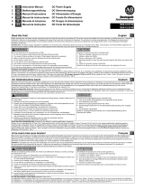
Fig. 1 / Bild 1
Functional diagram / Funktionsschaltbild
Fig. 2 / Bild 2
Timing diagram / Zeitliches Ablaufdiagramm
Buffer Capacitor
Charger &
Inrush Limiter
Buffer
Capacitor
Buffer Capacitor
Discharger
Status
LED
7 Active
6 (+)
Ready Monitor
+
-
Active Monitor
+
-
Optokoppler
Optokoppler
8 Ready
9 Inhibit
Optokoppler
Buffer
Capacitor
Shut-Down
Input / Output
Voltage Monitor
Back-up
Level
Selector
Reverse-
Polarity
Protection
-
-
+
+
Safety and
Over-
Voltage
Protection
Chassis
Ground
t
t
Line
Voltage
t
t
Charging Mode
t
Buffer Mode
Hold-up Time of Power Supply
Standby
Mode
10Hz
1.25Hz
Output
Voltage
Ready
Signal
Active
Signal
Pin 8
Pin 7
Status
LED
Fig. 3 / Bild 3
Buffer time / Pufferzeit
Fig. 4 / Bild 4
Wiring diagrams / Anschlussdiagramme
Fig. 5 / Bild 5
Dimensions / Abmessungen
PE
L
+
-
N
Power
Supply
+
-
Load
+
-
Buffer
Module
optional
Buffer Current, typ.
0
00.3 3s
5
15
10
20A
0.6 0.9 1.2 1.5 1.8 2.1 2.4 2.4
a: XLSBUFFER24
b: XLSBUFFER48
a
b
Buffer Current, typ.
0
3 18s
0.5
1.5
1.0
2.0A
6912 15
a
b
a: XLSBUFFER24
b: XLSBUFFER48
Signal wiring /
Signalverdrahtung
Active
6 (+)
5,1V
3mA
Inhibit
7
8
9
Ready
+ Vcc
Vcc: 10-35Vdc (XLSBUFFER24)
10-60Vdc (XLSBUFFER48)
UF20
10000059086 (version 00)
PU-366.010.38-10A
/