
INSTALLATION AND OPERATION MANUAL
MANUEL D'INSTALLATION ET D'UTILISATION
INSTALLATIONS- UND BEDIENUNGSANLEITUNG
MODEL
6430 POTATO PEELER
ML-136156
FORM 35005 Rev. A (March 2018)
Page 1 - English
Page 21 - French
Page 41 - German

– 2 –
© Hobart 2018
ENGLISH / CONTENTS
6430 CE Potato Peeler Section Page
Safety Information 1.0 3
Safety Guidelines 1.1 3
Warning Symbols 1.2 3
Liability 1.3 4
Foreword 2.0 4
General Information 3.0 4
Caring for Our Environment 4.0 4
Packaging Material 4.1 4
Disposal of Your Old Appliance 4.2 4
Safety Instruction 5.0 4
Never 5.1 5
Always 5.2 5
Using the Peeler 6.0 5
Operating for the First Time 6.1 6
Cleaning 6.2 7
Motor 6.3 8
Table 1 Technical Information 6.3.1 9
Unpacking and Handling 6.4 9
Installation 6.5 10
Location 6.6 10
Peeler Dimensions 6.6.1 11
Electrical Installation 6.7 12
Lexan Liner 6.8 13
Peel Trap 6.9 13
Operator Training 6.10 15
Peeler Maintenance 7.0 16
Lubrication 7.1 16
Fault Finding 7.2 16
Recommended Spares 8.0 17
Service Contact Numbers 9.0 18
Notes 10 19

– 3 –
1.0 SAFETY INFORMATION
The procedures and precautions contained in this manual are understood to apply to the
machinery only when it is used in the prescribed manner. If the machinery is used other than in
the recommended manner, the operator will be responsible for his/her own safety and for the
safety of the other persons who may be involved.
The information in this manual has been prepared to assist the operator to understand,
maintain and operate the peeler. In order to prevent accidents, read, understand and follow all
the precautions and warnings contained in this manual before installation or operating for the
rst time. This manual must be studied to obtain a clear understanding of the peeler and its
capabilities.
1.1 SAFETY GUIDELINES
Ensure sucient precautions are observed during manual handling of the peeler, particularly
when moving into position on the installation. Reference must be made to manual handling
regulations.
• Do not pressure clean this appliance. It is vital to adhere to the cleaning instructions detailed
in this manual.
• Do not remove any covers or loosen any ttings whilst the machine is operating.
• Ensure this manual is kept in an easily accessible place for future reference near the
peeler.
• All operators must be trained in the safe operation of the peeler.
• Ensure the power supply has been disconnected before attempting to service or move the
peeler.
• Rotating machinery and electricity are potentially hazardous and may cause injury if
sucient precautions are not taken prior to operating or servicing the machine.
• Always have your peeler regularly serviced; at least twice a year, depending on frequency
of use.
1.2 WARNING SYMBOLS
To identify the safety messages in this manual, the following symbols have been used.
The “Warning” symbol is found primarily where the corresponding information is
important for the safe use of the machinery.
The electrical hazard symbol is used when there are risks of an electrical nature. Prior
to servicing the machinery, always disconnect the power from the mains supply.

– 4 –
1.3 LIABILITY
Installations and repairs which are not carried out by Authorized technicians or the use of
other than original spare parts, and any technical alterations to the machine, may aect the
warranty set out in the standard conditions of sale.
2.0 FOREWORD
Hobart reserves the right to alter the design of their products without prior notice. Whilst every
eort is made to ensure this publication reects the latest design, the Company cannot guarantee
full compliance. Take pride in your 6430 Peeler - keep it clean and in good mechanical and
electrical condition.
3.0 GENERAL INFORMATION
The information and instructions contained in this manual may not cover all details or variations
in the equipment, nor provide for every eventuality to arise with installation, operation, or
maintenance. If additional information is required, please contact your local Hobart oce.
The peeler is tted with a “no volt release” safety feature to prevent automatic restarting after a
supply failure or disconnection from the mains.
4.0 CARING FOR OUR ENVIRONMENT
4.1 PACKAGING MATERIAL
The pallet and protective packing material have been selected from materials
that are environmentally friendly for disposal or can be normally be recycled.
Instead of throwing them away, please ensure they are recycled.
4.2 DISPOSAL OF YOUR OLD APPLIANCE
Old appliances contain materials that can be recycled. Please contact your local waste collection
centre, scrap merchant or local Hobart oce about potential recycling schemes.
5.0 SAFETY INSTRUCTIONS
A FULLY TRAINED AND COMPETENT PERSON MUST ONLY USE THE PEELER.
The following instructions must be observed when using the peeler.
NOTE: The peeler must only be used for the purpose it was designed and in line with the
supplied operating instructions.

– 5 –
5.1 NEVER
• Operate the peeler or attachments if a fault develops or the peeler is unsafe.
• Wear loose clothing.
• Attempt to reach into the hopper when operating.
• Access rotating parts.
• Use excessive force when operating which could aect the stability of the peeler.
• Operate the peeler if parts are disassembled.
• Use the peeler in an unsafe condition.
• Clean the peeler with scouring powder or a scouring pad.
5.2 ALWAYS
• Use the peeler in a well-lit area.
• Disconnect the mains electricity supply before cleaning the peeler.
• Clean the peeler daily.
• Stop peeler before removing peeled product or adding more product.
• Use the stop button to stop machine.
• Clean the hopper after use.
• Clean the peeler using mild soap and water.
• Service the peeler at least twice a year depending on the frequency of use.
• Use the peeler as intended and in line with the operating instructions.
6.0 USING THE PEELER
The model 6430 Peeler is designed to peel 30 to 33 lbs (13.5 to 15.0 kg) of product in 1 to 3
minutes using a 3/4 HP electric motor. The 6430 includes a 5-minute, synchronous timer which
increments from 1/2 to 5 minutes and uses single-phase or three-phase electrical service.
The peelers incorporate a reinforced peeling disc with abrasive permanently bonded to its
surface and a Lexan Liner for the inside of the hopper. The timer is mounted on the right side
of the discharge chute as standard but can be ordered on the left or changed in the eld. The
bottom of the peeler unit is cushioned with a rubber trim molding which also provides a seal.
Optional accessories include a peel trap, a portable stand and a peel trap basket.
This peeler is only for professional use by suitably trained persons. Ensure
operators have read and understood this manual and have received adequate training.

– 6 –
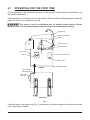
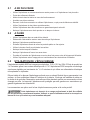
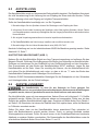
6.1 OPERATING FOR THE FIRST TIME
Prior to installation, test the electrical service to assure that it agrees with the specications on
the machine data plate.
Place the peeler on a suitable, sturdy, level surface. There should be adequate space around the
peeler for the user to operate the controls.
This peeler is only for professional use by suitably trained persons. Ensure
operators have read and understood this manual and have received adequate training.
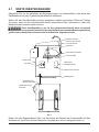
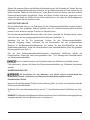
D
ATA PLATE
SWITCH
HOPPER TOP
BRACKET ASSEMBL
Y
SCREW
TUBE COUPLING
ABRASIVE DISC
JUNCTION BOX COVER
CONDUIT HOLE
RUBBER MOLDING
PEEL TRAP
DRAWER
LOCK WASHER
AND WASHER
PEELER
PEEL TRAP
Fig. 1
Using the lugs on the hopper top (Fig. 1) as locators, position the hopper top on the housing and
turn it clockwise into place.

– 7 –
Close and latch the discharge chute door.
Pour the product into the hopper. There should be room in the hopper for the product to move
around while peeling. Do NOT overload the peeler; peeler capacities are 30 to 33 lbs (13.5 to
15.0 kg) maximum for the 6430.
Turn on the water supply. On units with a disposer, turn on the disposer switch (Fig. 1). This will
open the valve.
Turn on the peeler. On units equipped with a timer, set the timer at the desired time.
Peeling times will vary depending on the type and condition of product. When the desired degree
of peeling has been reached, turn o the water (or disposer where applicable). Place a container
to catch the product under the discharge chute door.
NOTE: On units equipped with a timer, if the timer has expired, it will be necessary to reset the
timer to allow enough time for the product to be discharged.
After the product has been completely discharged, turn o the peeler and it is ready for a repeat
operation.
If the peeler is equipped with a peel trap, it will be necessary to empty the peel trap drawer
occasionally (after a few batches).
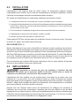
6.2 CLEANING
Disconnect the mains electricity supply before cleaning or servicing this
machine.
The peeler should be cleaned after the peeling operation has been completed.
As soon as the peeling has been completed and BEFORE the hopper has had time to dry, turn
on the water and ush the interior of hopper. Turn o the water. Remove the hopper top and
clean it in a sink.
Lift out the abrasive disc, which is not fastened to the shaft, and scrub it with a brush and mild
soap. Clean the housing beneath the abrasive disc with mild soap and water.
Turn on the water and thoroughly clean the interior of the hopper using a mild soap and a brush.
Rinse thoroughly.
NOTE: If the abrasive disc should stick and is NOT easily
removed, it may be loosened by removing the hex head
screw on top of the hub and threading a longer screw
(such as 5/16”-18 x 1/2”) in until disc loosens.
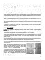
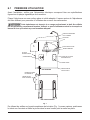
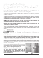
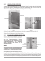
To remove the Lexan Liner, unlatch the exterior latch on
the outside of the hopper and push the keeper out of the
hole (Fig. 2). Slide the liner out from under the retaining
brackets. Take to the sink and scrub with a nonabrasive
brush, using soap and water to clean. Allow to air dry
before installing into the hopper.
KEEPER
Fig. 2

– 8 –
If the drawer is equipped with a peel trap, remove the peel trap drawer and thoroughly clean the
drawer, as well as the peel trap interior.
The discharge chute MUST be left open when unit is NOT in use to prolong life of the door
seal.
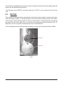
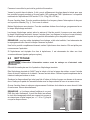
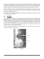
6.3 MOTOR
This machine is equipped with a manual-reset overload protection switch, located on the motor
inside the peeler housing. If, during operation, the motor should overheat and trip this switch,
turn the timer o and allow the motor to cool for several minutes. To reset the switch, remove the
top screw from the cover plate (Fig. 3), rotate the cover plate and push the red button (Fig. 3).
Reposition round cover plate and replace top screw in threaded hole.
If the overload protection switch persists in tripping, contact your local Hobart Service Oce.
RED BUTTON
COVER PLATE
Fig. 3

– 9 –
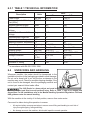
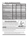
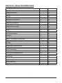
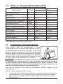
6.3.1 TABLE 1 TECHNICAL INFORMATION
Description Units 6430
1 Phase 3 Phase
Peeler Power kW (hp) .56 (3/4) .746 (1)
Maximum Speed of Rotating
Part (50Hz)
RPM 1425 1450
Nominal Electrical Supply Volts 240 240
Full Load Current At Above
Voltage
Amps 7.84 4.36
Locked Rotor Current At Above
Voltage
Amps 35.9 26.1
Recommended Fuse Size Amps 15 15
Minimum Ambient Temperature °C 0 0
Maximum Ambient Temperature °C 40 40
Peeler Weight Kg (Lbs) 63.6 (140) 63.6 (140)
Noise Level dB ##less than 70 ##less than 80
Shipping Weight Kg (Lbs) 66.8 (147) 66.8 (147)
Shipping Dimensions LxWxH cm 71.1 x 59.7 x 77.2 71.1 x 59.7 x 77.2
Storage Conditions °C,
% RH
+5 to +38,
85
+5 to +38,
85
Class of Appliance -- Class 1 Class 1
Enclosure IP Rating -- IP45 IP35
## In accordance with EN-ISO 12001:1996.
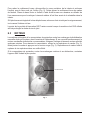
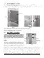
6.4 UNPACKING AND HANDLING
Whenever possible, the peeler should be transported to the
installation position in the packaging provided to avoid damage.
Do not use a sharp knife to cut into the box as damage to the
machine may occur. Check for possible shipping damage. If the
unit is found to be damaged, save the packaging material and
contact your nearest Hobart sales oce.
The 6430 Peeler is a heavy object and must be
correctly handled and lifted to avoid personal injury. Refer to Table 1, page 9 for weights and
dimensions. For UK installations refer to the Manual Handling Operations Regulations 1992 and
HSE guidance notes for manual handling.
With the machine in the vicinity of its nal position, remove from outer carton.
Care must be taken during this operation to ensure:
• All required safety measures are taken to ensure correct lifting and handling to avoid risk of
injury through dropping, falling and tilting.
• No damage occurs to the machine, which could impair the normal operation.

– 10 –
6.5 INSTALLATION
The peeler was inspected before leaving the factory. The carrier assumes full responsibility
for the safe delivery upon acceptance of the shipment. Check for possible shipping damage
immediately after receipt.
If the peeler is found to be damaged, complete the following steps;
1. Carrier must be notied within ve business days of receipt.
2. Carrier’s local terminal must be notied immediately upon discovery (note time, date, and
who was spoken to), and follow up and conrm with written or electronic communication.
3. All original packing materials must be kept for inspection purposes.
4. The peeler cannot have been moved, installed, or modied.
5. Notify Hobart customer care at (800) 333-7447.
This machine MUST be cleaned after installation and before being put into service. Refer to
section 6.2, page 7 for instructions.
PEELER UNIT (FIG. 1)
Remove the peeler from its shipping carton and remove the hopper top. Remove the ll tube and
bracket assembly from the peeler housing and the cloth bag containing the ll tube gasket and
acorn nuts. Do NOT remove the rubber molding on bottom of peeler. Lay the peeler on its side.
Slightly loosen the clamp that attaches the drain hose and pull the drain hose down so that it
extends approximately 7/8” below the bottom of peeler housing. Tighten the clamp.
On units that will NOT use a peel trap, attach the bottom cover plate using the bolts and washers
supplied with the unit.
6.6 LOCATION
The peeler is not suitable for outdoor installation. The peeler must only be operated
by trained sta and must be installed in a area where the use and maintenance is restricted to
trained personnel.
The peeler must be installed on a horizontal, at surface, which is level to a minimum of 1mm
in a 1 metre side to side and front to back. Select a suitable, at, level surface that can support
the weight of the peeler when full. Refer to Table 1, page 9 for weights and dimensions. In areas
where stability may be an issue, the machine should be secured in position.
Ensure there is sucient space around the peeler for the user to operate the controls. Servicing
may be more dicult because of reduced clearances and you should always check that equipment
specications permit the close proximity of other equipment. Refer to pages 11 and 12 for the
overall dimensions of the peeler and clearance required.

– 11 –
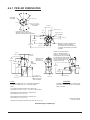
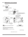
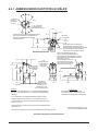
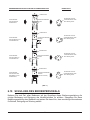
6.6.1 PEELER DIMENSIONS
MODEL 6430 PEELER
(WITH PEEL TRAP)
NOTES:
ALL DIMENSIONS TAKEN FROM FLOOR LINE MAY BE
INCREASED AS MUCH AS 13/16” (2.1 cm) BY LEG ADJUSTMENT.
APPROXIMATE SHIPPING WEIGHT OF PEELER AND
PEEL TRAP UNIT: 201 Lbs (91.2 Kg)
APPROXIMATE SHIPPING WEIGHT OF PEELER LESS
PEEL TRAP UNIT: 147 Lbs (66.7 Kg)
NET WEIGHT OF PEELER AND PEEL TRAP UNIT: 190 Lbs (86.2 Kg)
PLUMBING CONNECTIONS MUST COMPLY WITH
APPLICABLE SANITARY, SAFETY AND PLUMBING
CODES IN FORCE.
WARNING
P1 - WATER CONNECTION: ST’D 1/2” FEMALE PIPE THREAD
P2 - DRAIN CONNECTION: ST’D 2” MALE PIPE THREAD
11-7/8”
(30.2 cm)
55-1/2”
(141.0 cm)
49-1/4”
(125.1 cm)
41”
(104.1 cm)
P2
P2P1
P1
11-7/8”
(30.2 cm)
27-3/32”
(68.8 cm)
8-1/8” (20.6 cm)
13-1/4”
(33.7 cm)
37”
(94.0 cm)
7-1/2”
(19.1 cm)
PEELER IS SECURED TO PEEL
TRAP AS SHOWN, BY FOUR
SCREWS, LOCATED RADIALLY
FROM CENTER LINE. ASSEMBLY
CAN BE MADE SO THAT PEELER
WILL DISCHARGE IN ANY ONE
OF THE FOUR POSITIONS AS
SHOWN IN TOP VIEW.
WATER & ELECTRIC CONNECTIONS
REMAIN IN SAME RELATION TO
DISCHARGE CHUTE WHEN PEELER
IS TURNED TO ANOTHER DISCHARGE
POSITION.
PLAN VIEW OF PEEL TRAP
SHOWING HOLES IN LEGS FOR
BOLTING TO FLOOR WHEN REQUIRED.
19” (48.3 cm)
SPACE REQ’D FOR
REMOVAL OF PEEL
TRAP STRAINER
27-1/4”
(69.2 cm)
41-3/8”
(105.1 cm)
11-1/4” (28.6 cm)
22-11/16”
(57.6 cm)
5/8”
(1.6 cm)
LEGEND
7-5/16” (18.6 cm)
7-5/16” (18.6 cm)
22-13/16” (57.9 cm)
1/2” (1.3 cm) DIA
4 HOLES SPACED
AS SHOWN
PEEL TRAP
STRAINER
8-5/16” (21.1 cm)
DIA. OPENING
REMOVE PLAT E
TO ADJUST
BELT TENSION
PEEL
TRAP
STRAINER
15-3/4”
(40.0 cm)
21” DIA
(53.3 cm)
Installation Diagram (With Trap)

– 12 –
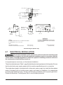
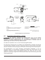
MODEL 6430 PEELER
(WITHOUT TRAP)
NOTE:
NET WEIGHT OF PEELER
DOMESTIC SHIPPING WEIGHT OF PEELER
PLUMBING CONNECTIONS MUST COMPLY WITH
APPLICABLE SANITARY, SAFETY AND PLUMBING
CODES IN FORCE.
WARNING
- 140 Lbs (63.6 Kg)
- 147 Lbs (66.7 Kg)
P1 - WATER CONNECTION: ST’D 1/2” FEMALE PIPE THREAD
P2 - DRAIN HOSE: 2-3/8” I.D. x 2-3/4” O.D.
5-11/32”
(13.6 cm)
4-3/4”
(12.1 cm)
DISCHARGE
CHUTE
15”
(38.1 cm)
15-3/4”
(40.0 cm)
27-1/2”
(69.9 cm)
21” DIA
(53.3 cm)
REMOVE PLAT E
TO ADJUST
BELT TENSION
35-13/16”
(91.0 cm)
11-7/8”
(30.2 cm)
1-3/4”
(4.4 cm)
APPROX.
1-3/4”
(4.4 cm)
5” (12.7 cm)
7-5/16” (18.6 cm)
7-5/16” (18.6 cm)
21-1/4” (54.0 cm)
27-1/4”
(69.2 cm)
11-1/4” (28.6 cm)
5/8”
(1.6 cm)
8-5/16” (21.1 cm)
DIA. OPENING
19-1/4”
(48.9 cm)
LEGEND
P1 P2
Installation Diagram (Without Trap)
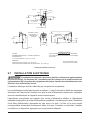
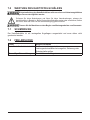
6.7 ELECTRICAL INSTALLATION
The electrical installation of the peeler must conform to the local electricity board
regulations. When installed in the United Kingdom the installation must be in accordance with the
current edition of the IEE Regulations for electrical equipment in buildings and must conform to
the requirements of the Electricity at work act.
A competent person must carry out the electrical installation.
The technical data shown in Table 1, page 9 details the electrical requirements for the peeler. Ensure
that the electrical power supply agrees with the machine specication prior to connection.
The single-phase peeler is equipped with a three-wire power supply cord and the three-phase
peeler is equipped with a four-wire power supply cord ready for installation of an appropriate
grounding-type attachment plug. The plug and its mating receptacle must be properly grounded.
Contact an electrician. Provide proper fuse or circuit breaker protection.

– 13 –
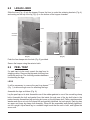
6.8 LEXAN LINER
Slide the liner (Fig. 4) into the hopper. Ensure the liner is under the retaining brackets (Fig. 4)
and resting on the top of the lip (Fig. 4) on the bottom of the hopper chamber.
LIP
LINER
RETAINING
BRACKETS
KEEPER
(Fig. 4) (Fig. 5)
Push the liner keeper into the hole (Fig. 5) provided.
Secure the keeper using the exterior latch.
6.9 PEEL TRAP
If a peel trap is to be used, unpack the trap from its
shipping carton. Remove the legs and cloth bag from
inside the peel trap. The cloth bag contains hardware
for attaching the legs.
LEGS
It will be necessary to remove the peel trap drawer
(Fig. 1) to allow enough room for attaching the legs.
Assemble the legs as follows (Fig. 6):
Lay the peel trap on its side. Assemble one of the rubber gaskets to one of the curved leg clamp
bolts. Assemble the bolt and gasket from the inside, through one of the leg bolt holes in the
peeler housing. Assemble a leg and a leg slot cover on the leg clamp bolt. Place a stainless steel
washer and acorn nut onto the clamp bolt and partially tightened, set unit upright. Each leg has
an upper and lower leg clamp bolt assembly. When all are assembled and partially tightened,
set unit upright. Adjust each leg to a suitable height such that the unit is level, and tighten the
acorn nuts.
ACORN NUT
WASHER
SLOT COVER LEG
RUBBER GASKET
CLAMP BOLT
Fig. 6

– 14 –
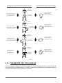
PEELERS
The peeler may be positioned on the peel trap in one of four positions. Each of the positions will
cause the peel trap drawer to be located in a dierent position relative to the discharge chute.
The peel trap drawer may be directly beneath the discharge chute, to the right, left or rear (see
Fig. 7).
After selecting the most convenient position for the peel trap drawer, remove the cover disc from
the appropriate hole in the peel trap top and position the peeler on top of the peel trap, with the
peeler drain hose extending through selected hole (Fig. 7).
The cloth bag shipped in the peel trap drawer contains the capscrews, lockwashers and washers
(Fig. 1) necessary for fastening the peeler to the peel trap.
Excessive tightening of screws may distort the housing.
If desired, the peel trap legs may be bolted to the oor.
PLUMBING
Plumbing connections must comply with applicable sanitary, safety and plumbing
codes.
Peeler Unit
Using the supplied acorn nuts and gasket, attach the ll tube and bracket assembly (Fig. 1) to
the peeler.
Connect a cold water supply to the 1/2” ll tube coupling (Fig. 1).
NOTE: A globe valve for controlling water supply should be installed in the water supply line at
a location convenient to the operator.

– 15 –
T
o position peel trap
dr
awer BENEATH the
discharge chute:
T
o position peel trap
dr
awer to the RIGHT
of discharge chute:
T
o position peel trap
dr
awer to the LEFT
of discharge chute:
T
o position peel trap
dr
awer to the REAR
of discharge chute:
Remove cover disc and
place drain hose through
this hole.
Remove cover disc and
place drain hose through
this hole.
Remove cover disc and
place drain hose through
this hole.
Remove cover disc and
place drain hose through
this hole.
Discharge
Chute
Discharge
Chute
Discharge
Chute
Peel Tr ap
Drawer
Peel Tr ap
Drawer
Discharge
Chute
Peel Tr ap
Drawer
Peel Tr ap
Drawer
(in Rear)
RELATIONSHIP OF PEELER WITH TRAP VIEW OF TOP OF PEEL TRAP
(Fig. 7)
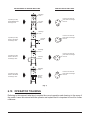
6.10 OPERATOR TRAINING
Referring to this manual, take time to explain the correct operation and cleaning to the users of
the peeler. Leave this manual with the operator and explain that it is important to use it for further
reference.

– 16 –
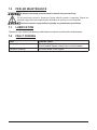
7.0 PEELER MAINTENANCE
A Hobart trained and competent person should carry out servicing.
Do not remove any covers or loosen any ttings whilst the peeler is operating. Ensure the
electrical supply has been isolated before attempting to service or move the peeler.
Disconnect power supply before beginning any maintenance procedures.
7.1 LUBRICATION
The peeler uses sealed ball bearings and therefore requires no lubrication maintenance.
7.2 FAULT FINDING
Fault Possible cause
Peeler will not operate. Peeler not plugged in.
Circuit breaker tripped, check fuse or circuit breaker.
Excessive foaming. Too much water in the hopper.

– 17 –
8.0 RECOMMENDED SPARES
00-479494-00004 Liner Assembly
00-875573 Hardware Kit
00-012430 Key 3/16 Sq. x 11/4

– 18 –
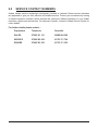
9.0 SERVICE CONTACT NUMBERS
Hobart trained service technicians strategically located at national Hobart service branches
are prepared to give you fast, ecient and reliable service. Protect your investment by having
a Hobart inspection contract, which assures the continued, ecient operation of your Hobart
machines, spares and accessories. For disposal of peeler, contact a Hobart Service Centre for
return details.
For further details please contact: -
Department Telephone Facsimile
SALES: 07002 101 101 02088 864 396
SERVICE 07002 202 202 01733 371 709
SPARES 07002 303 303 01733 371 332

– 19 –
10.0 NOTES

– 20 – FORM 35005 Rev. A (March 2018)
Seite wird geladen ...
Seite wird geladen ...
Seite wird geladen ...
Seite wird geladen ...
Seite wird geladen ...
Seite wird geladen ...
Seite wird geladen ...
Seite wird geladen ...
Seite wird geladen ...
Seite wird geladen ...
Seite wird geladen ...
Seite wird geladen ...
Seite wird geladen ...
Seite wird geladen ...
Seite wird geladen ...
Seite wird geladen ...
Seite wird geladen ...
Seite wird geladen ...
Seite wird geladen ...
Seite wird geladen ...
Seite wird geladen ...
Seite wird geladen ...
Seite wird geladen ...
Seite wird geladen ...
Seite wird geladen ...
Seite wird geladen ...
Seite wird geladen ...
Seite wird geladen ...
Seite wird geladen ...
Seite wird geladen ...
Seite wird geladen ...
Seite wird geladen ...
Seite wird geladen ...
Seite wird geladen ...
Seite wird geladen ...
Seite wird geladen ...
Seite wird geladen ...
Seite wird geladen ...
Seite wird geladen ...
Seite wird geladen ...
-
 1
1
-
 2
2
-
 3
3
-
 4
4
-
 5
5
-
 6
6
-
 7
7
-
 8
8
-
 9
9
-
 10
10
-
 11
11
-
 12
12
-
 13
13
-
 14
14
-
 15
15
-
 16
16
-
 17
17
-
 18
18
-
 19
19
-
 20
20
-
 21
21
-
 22
22
-
 23
23
-
 24
24
-
 25
25
-
 26
26
-
 27
27
-
 28
28
-
 29
29
-
 30
30
-
 31
31
-
 32
32
-
 33
33
-
 34
34
-
 35
35
-
 36
36
-
 37
37
-
 38
38
-
 39
39
-
 40
40
-
 41
41
-
 42
42
-
 43
43
-
 44
44
-
 45
45
-
 46
46
-
 47
47
-
 48
48
-
 49
49
-
 50
50
-
 51
51
-
 52
52
-
 53
53
-
 54
54
-
 55
55
-
 56
56
-
 57
57
-
 58
58
-
 59
59
-
 60
60


in anderen Sprachen
- English: Hobart 6430 Peeler Owner's manual
- français: Hobart 6430 Peeler Le manuel du propriétaire
Andere Dokumente
-
Westmark 1259 2270 Datenblatt
-
Epson TM-L90 with Peeler Benutzerhandbuch
-
Custom Audio Electronics Lola-lp2 Benutzerhandbuch
-
OKI LD620D Bedienungsanleitung
-
Tally Dascom DL-310 Benutzerhandbuch
-
TSC TX200 Series Benutzerhandbuch
-
Intermec 7422 Benutzerhandbuch
-
-
-