
Documentazione
Tecnica
T25
rev. 0.1
03/2003
©
CAME
CANCELLI
AUTOMATICI
ZBKS
CANCELLI AUTOMATICI
319T25
SERIE Z |
Z SERIES
|SÉRIE Z |
BAUREIHE
Z|
SERIE Z
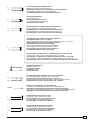
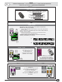
240 mm
120 mm
145 mm
320 mm
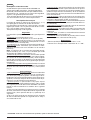
Descrizione quadro comando
Quadro elettrico per motoriduttore BK800S con alimenta-
zione 230V monofase; frequenza 50÷60 Hz. Progettato e
costruito interamente dalla CAME Cancelli Automatici
S.p.A., risponde alle vigenti norme di sicurezza, con grado
di protezione IP54. Scatola in ABS, dotata di presa per il
riciclo d'aria. Garantito 24 mesi salvo manomissioni.
Descrizione tecnica scheda base
La scheda comando va alimentata sui morsetti L1 e L2
ed è protetta in ingresso con fusibile 8A. I dispositivi di
comando sono a bassa tensione (24V), e sono protetti
con fusibile da 2A. La potenza complessiva degli acces-
sori a 24V, non deve superare i 20W. Il tempo lavoro è
fisso a 150 secondi.
Sicurezza
Le fotocellule possono essere collegate e predisposte per:
- Riapertura in fase di chiusura (2-C1);
- Richiusura in fase di apertura (2-CX, vedi dip 8-9);
- Stop parziale, arresto del cancello se in movimento con conseguente
predisposizione alla chiusura automatica (2-CX,vedi dip 8-9);
- Stop totale (1-2), arresto del cancello escludendo l'even-
tuale ciclo di chiusura automatica; per riprendere il movi-
mento bisogna agire sulla pulsantiera o sul radiocomando;
Nota: se un contatto di sicurezza normalmente chiuso (2-
C1, 2-CX, 1-2) si apre, viene segnalato dal lampeggio del
LED di segnalazione (n°11);
- Rilevazione di presenza ostacolo. A motore fermo (can-
cello chiuso, aperto o dopo un comando di stop totale),
impedisce qualsiasi movimento se i dispositivi di sicurez-
za (es.fotocellule) rilevano un ostacolo;
- Funzione del test di sicurezza. Ad ogni comando di aper-
tura e chiusura delle ante, la centralina ne verifica l'effi-
cienza delle fotocellule (vedi pag. 7).
Altre funzioni selezionabili
- Chiusura automatica. Il temporizzatore di chiusura auto-
matica si autoalimenta a finecorsa in apertura. Il tempo
prefissato regolabile, é comunque subordinato dall'inter-
vento di eventuali accessori di sicurezza e si esclude dopo
un intervento di «stop» totale o in mancanza di energia
elettrica;
- Apertura parziale. Apertura del cancello per passaggio
ITALIANO
ATTENZIONE: prima di intervenire all'interno dell'apparecchiatura, togliere la tensione di linea
pedonale, viene attivata collegandosi ai morsetti 2-3P ed
è regolabile mediante trimmer AP.PARZ.. Con questa fun-
zione, la chiusura automatica varia nel seguente modo:
1) Dip 12 in ON: dopo un'apertura parziale, il tempo di chiu-
sura automatica è indipendente dalla regolazione del trim-
mer TCA e dalla posizione del dip 1, ed è fisso a 8 secon-
di.
2) Dip 12 in OFF: dopo un'apertura parziale, il tempo di
chiusura automatica è regolabile solo se il dip 1 è posizio-
nato in ON;
- Lampada ciclo. Lampada che illumina la zona di mano-
vra, rimane accesa dal momento in cui l'anta inizia l'aper-
tura fino alla completa chiusura (compreso il tempo di chiu-
sura automatica). Nel caso non venga inserita la chiusura
automatica, rimane accesa solo durante il movimento (E-
EX);
- Lampada di cortesia. Lampada che illumina la zona di
manovra, dopo un comando di apertura rimane accesa con
un tempo fisso di 5 minuti e 30 secondi (E-EX, vedi pag.
8);
- Funzione a "uomo presente". Funzionamento del cancel-
lo mantenendo premuto il pulsante (esclude il funziona-
mento del radiocomando);
- Prelampeggio di 5 secondi sia in apertura sia in chiusura
dell'anta;
- Funzione master; il quadro assume tutte le funzioni di
comando nel caso di due motori abbinati (vedi pagina 13);
- Funzione slave; il quadro viene esclusivamente pilotato
dal "MASTER" (vedi pagina 13);
- Abilitazione alle funzioni di stop parziale o richiusura du-
rante l'apertura, contatto normalmente chiuso (2-CX), se-
lezionare una delle due funzioni tramite dip, vedi selezioni
funzioni.
Regolazioni
- Trimmer AP.PARZ. = Apertura parziale: da 1" a 14";
- Trimmer TCA.= Tempo chiusura automatica: da 1" a 150";

-2-
Description of control panel
Control panel for gear motor BK800S, powered by 230V
single-phase; frequency 50-60 Hz.
Designed and built entirety by CAME Cancelli automatici
S.p.A., in full compliance with current safety standards,
and with an IP54 protecting rating.
Housing in ABS is equipped with vents to provide internal
air circulation. Guaranteed 24 months, unless tampered
with.
Technical description motherboard
This control board is powered across terminals L1 and
L2, and is protected by fuse on the main power line 8A.
Control systems are powered by low voltage and protect-
ed with by a 2A fuse.
The total power consumption of 24 V accessories must
not exceed 20W.
Fixed operating time of 150 seconds.
Safety
Photocells can be connected to obtain:
- Re-opening during the closing cycle (2-C1);
- Re-closing during the opening cycle (2-CX, see dip 8-9);
- Partial stop, shutdown of moving gate, with activation of
an automatic closing cycle (2-CX, see dip 8-9);
- Total stop (1-2), shutdown of gate movement without
automatic closing; a pushbutton or radio remote control
must be actuated to resume movement;
Note: If an normally closed safety contact (2-C1, 2-CX, 1-
2) is opened, the LED (n°11) will flash to indicate this
fact;
- Obstacle presence detection. When the motor is stopped
(gate is closed, open or half-open after an emercency stop
command), the transmitter and the control pushbutton will
be deactivated if an obstacle is detected by one of the
safety devices (for example, the photocells);
- Safety test function. The control unit will now check the
safety system every time an opening or closing command
is given (see pag. 7).
Other functions
- Automatic closing: The automatic closing timer is auto-
matically activated at the end of the opening cycle. The
preset, adjustable automatic closing time is automatical-
ly interrupted by the activation of any safety system, and
is deactivated after a STOP command or in case of pow-
er failure;
- Partial opening. Opening of the gate to allow for foot
traffic; activated by connecting to terminals 2-3P and ad-
justed with the AP-PARZ. trimmer. With this function, the
automatic closing can vary in the following way:
1) Dip 12 set to ON: after a partial opening, the time for
automatic closing functions independently of the adjust-
ment of the TCA trimmer and of the position of Dip 1; it is
set at 8 seconds.
2) Dip 12 set to OFF: after a partial opening, the time for
automatic closing is adjustable only if Dip 1 is set to ON.
- Cycle lamp. The lamp which lights the manoeuvring zone:
it remains lit from the moment the doors begin to open
until they are completely closed (including the time re-
quired for the automatic closure). In case automatic clo-
sure is not enabled, the lamp remains lit only during move-
ment (E-EX);
ENGLISHENGLISH
ENGLISHENGLISH
ENGLISH
IMPORTANT: Shut off the mains power before servicing the inside of the unit.
- Courtesy Light. A light that illuminates the manoeuvring
zone; after an opening command, the light remains on for
a fixed time of 5 minutes and 30 seconds (E-EX, see
page 8);
- "Operator present" function: Gate operates only when
the pushbutton is held down (the radio remote control
system is deactivated);
- Pre-flashing for 5 seconds, while the door is opening
and closing;
- Master function; the panel assumes all the command
functions when two paired motors are used (see page 13);
- Slave function; this panel is exclusively controlled by
the “MASTER” (see p. 13);
- Enabling functions of partial-stop or re-closure during
opening; normally-closed contact (2-CX), select one of
the two functions by setting dip, see selection of func-
tions;
Adjustments
- Trimmer AP.PARZ. = Partial opening: 1" to 14";
- Trimmer TCA = Automatic closing time: 1" to 150";

-3-
Description armoire de commande
Armoire électrique pour motoréducteur BK800S avec
alimentation 230V monophasée; fréquence 50÷60 Hz.
Il a été entièrement concu et construit par la Société CAME
Cancelli Automatici S.p.A., conformément aux normes
de sécurité en vigueur avec degré de protection IP54.
Boîtier en ABS muni de prise de circulation d’air. Garantie
24 mois sauf en cas d’endommagement.
La carte de commande doit être alimentée sur les
bornes L1 et L2 et elle est protégée en entrée par un
fusible de ligne 8A.
Description technique carte base
Les dispositifs de commande sont à basse tension et
protégés avec fusible de 2A. La puissance totale des ac-
cessoires à 24V, ne doit pas dépasser 20W.
Temps de fonctionnement fixe de 150 secondes.
Sécurité
Il est possible de brancher des photocellules et de les
programmer pour:
- Réouverture en phase de fermeture (2-C1);
- Réfermeture en phase de ouverture (2-CX, voir dip 8-9);
- Stop partiel, arrêt du portail, si en mouvement, et con-
séquente programmation pour la fermeture automatique
(2-CX, voir dip 8-9);
- Stop total (1-2) arrêt du portail et désactivation d’un éven-
tuel cycle de fermeture automatique; pour activer de nou-
veau le mouvement, il faut agir sur les boutons-poussoirs
ou sur la radiocommande);
Remarque: Le LED de signalisation (n°11) qui clignote
indique qu'un contact de sécurité normalment fermé
(2-C1, 2-CX, 1-2) s'ouvre;
- Détection de présence d'obstacle. Quand le moteur est
arrête (portail fermé, ouvert ou semiouvert, cette posi-
tion est obtenue avec une commande de stop total), an-
nule toute fonction de l'émetteur ou du bouton-poussoir
en cas d'obstacle détecté par les dispositifs de sécurité
(ex. Photocellules);
- Fonction du test de securité. Cela permet au boîtier de
vérifier le bon fonctionnement des despositifs de securité
aprés chaque commande d'ouverture ou de fermeture (voir
pag. 7).
Autres fonctions
- Fermeture automatique. Le temporisateur de fermeture
automatique est autoalimenté à la fin du temps de la course
en ouverture. Le temps réglable est programmé, cepen-
dant, il est subordonné à l’intervention d’éventuels acces-
soires de sécurité et il est exclu après une intervention
de “stop” ou en cas de coupure de courant;
- Ouverture partielle. Ouverture de la grille pour le passa-
ge pour piétons, elle est enclenchée en la reliant aux bor-
nes 2-3 P et est réglable par le trimmer AP.PARZ.. Avec
cette fonction, la fermeture automatique varie de la façon
suivante:
1) Dip 12 sur ON: après une ouverture partielle, le temps
de fermeture automatique est indépendant du réglage du
trimmer TCA et de la position du dip 1, et est fixe à 8
secondes.
2) Dip 12 sur OFF : après une ouverture partielle, le temps
de fermeture automatique est réglable seulement si le dip
1 est positionné sur ON;
FRANÇAIS
ATTENTION: avant d'intervenir à l'intérieur de l'appareillage, couper la tension de ligne
- Lampe cycle. Ampoule qui illumine la zone de manoeu-
vre: elle reste allumée à partir du moment ou les portes
commencent l'ouverture jusqu'à la fermeture complète (y
compris le temps de fermeture automatique). Si elle n'est
pas insérée la fermeture automatique reste allumée seu-
lement durant le mouvement (E-EX);
- Lampe passage. Lampe qui illumine la zone de manoeu-
vre, après une commande d’ouverture elle reste allumée
pour une durée fixe de 5 minutes et 30 secondes (E-EX,
voir p.8);
- Fonction “homme mort”. Fonctionnement du portail en
maintenant appuyé le bouton-poussoir (exclut la fonction
de la radiocommande);
- Prè-clignotement de 5 secondes en ouverture comme
en fermeture de la porte;
- Fonction master; le pupitre prend toutes les fonctions
de commande si les deux moteurs sont mis ensemble
(voir p. 13);
- Fonction slave; le pupitre est exclusivement piloté par
le “ MASTER ” (voir page 13);
- Activation des fonctions d'arrêt partiel ou de fermeture
durant l'ouverture, contact normalment fermé (2-CX), sé-
lectionner une des deux fonctions à l'aide d'un dip (voir
sélection fonctions);
Réglages
- Trimmer AP.PARZ.= Ouverture partielle: de 1" à 14";
- Trimmer T.C.A. = Temps de fermeture automatique : de
1" à 150";

-4-
Beschreibung des Steuergeräts
Schalttafel für Getriebemotoren BK800S mit 230V-
Einphasenstromversorgung; Frequenz: 50-60 Hz.
Vollständig von der CAME Cancelli Automatici S.p.A.
gemäß geltender Sicherheilsnormen entwickelt und
hergestellt. Schutzklasse IP54.
ABS-Gehäuse mit Luftklappe.
24 Monate Garantie, vorbehaltlich unsachgemäßer
Handhabung und Montage.
Technische beschreibung grundplatine
Die grundplatine wird mit einer Spannung über die
Klemmen L1 und L2 gespeist und ist am Eingang mit
einer Hauptsicherung 8A.
Die Steuerungen erfolgen mit Niederspannung und geschüt-
zen enie 2A-Sicherung. Die Gesamtleistung des 24-V-Zu-
behörs darf 20W nicht überschreiten.
Feste Laufzeit von 150 Sekunden.
Sicherheitsvorrichtungen
Die Lichtschranken können für folgende Funktionen ange-
schlossen bzw. vorbereitet werden:
- Wiederöffnen beim Schließen (2-C1);
- Wiederschließen beim Öffnen (2-CX, siehe dip 8-9);
- Teilstop, Stillstand des Tores während des Torlaufs, mit
darauffolgender automatischer Torschließung (2-CX, siehe
dip 8-9);
- Totalstop (1-2), sofortiger Stillstand des Tores mit Aus-
schluß eventueller Schließautomatik: Fortsetzung des Tor-
laufs über Drucktaster- bzw. Funksteuerung;
Hinweis: Wenn sich ein normalerweise geschlossener (NC)
Sicherheitskontakt (2-C1, 2-CX, 1-2) öffnet, wird dies durch
Blinken der Kontrolleuchte angezeigt (11);
- Ermittlung eventuell vorhandener Hindernisse. Bei still-
stehendem Motor (Tor geschlossen, geöffnet oder durch
eine Totalstop-Steuerung halb geöffnet) wird bei durch die
Sicherheitsvorrichtungen (z.B.:Lichtschranken) erfaßtem
Hindernis jede Sensor-oder Drucktasterfunktion annulliert;
- Sicherheitstest-Funktion. Dadurch besteht die Möglich-
keit, die Leistungsfähigkeit der Sicherheitsvorrichtungen
nach jeder Öffnungs-und Schließsteuerung zu überprüfen
(siehe Seite 7).
Andere funktionen
- Schließautomatik. Der Schließautomatik-Zeischalter
speist sich beim Öffnen am Ende der Torlaufzeit selbst.
Die voreingestellte Zeit ist auf jeden Fall immer dem Ein-
griff eventueller Sicherheitsvorrichtungen untergeordnet und
schließt sich nach einem “Stop”-Eingriff bzw. bei Strom-
ausfall selbst aus;
- Teilweises Öffnung. Das Öffnen des Tors für das Durch-
lassen von Fußgängern wird durch Anschluß an die Klem-
men 2-3P aktiviert und kann über den Trimmer AP.PARZ.
eingestellt werden. Wenn diese Funktion aktiviert ist, vari-
iert das automatische Schließen folgendermaßen:
1)Dip 12 auf ON: Nach einem teilweisen Öffnen erfolgt das
Schließen des Tor unabhängig von der Einstellung des Trim-
mer TCA und der Stellung des Dip-Switch 1, und zwar nach
einer vorgegebenen Zeit von 8 Sekunden;
2)Dip 12 auf OFF: Nach einem teilweisen Öffnen kann die
Zeit für das automatische Schließen nur dann eingestellt
werden, wenn der Dip-Switch 1 auf ON steht;
DEUTSCHDEUTSCH
DEUTSCHDEUTSCH
DEUTSCH
ACHTUNG: Das Gerät vor Eingriffen im inneren spannungsfrei schalten
- Betriebszyklus-Anzeigeleuchte. Das Licht, das den Tor-
bereich beleuchtet, bleibt vom Beginn des Öffnens bis zum
vollständigen Schließen der Torflügel eingeschaltet (ein-
schließlich Wartezeit für automatisches Schließen). Wenn
das automatische Schließen nicht zugeschaltet ist, bleibt
das Licht nur während der Torbewegung eingeschaltet (E-
EX);
- Torbeleuchtung. Nachdem der Befehl zum Öffnen des Tors
gegeben worden ist, bleibt das Licht, das den Manöver-
bereich am Tor beleuchtet, für eine vorgegebene Zeit von 5
Minuten und 30 Sekunden eingeschaltet (E-EX; siehe S.
8);
- Funktion “Bedienung vom Steuerpult”. Torbetrieb durch
Drucktasterbetätigung (Funkfernsteuerung ausgeschlos-
sen);
- Vorblinken. Das Licht blinkt sowohl vor dem Öffnen als
auch vor dem Schließen zunächst 5 Sekunden lang;
- Master-Funktion (übergeordnet). Wenn zwei Motoren kom-
biniert werden, übernimmt die Schalttafel alle Steuerungs-
funktionen (siehe S. 13);
- Slave-Funktion (untergeordnet). Die Schalttafel unterliegt
komplett der Steuerung durch die MASTER-Schalttafel (sie-
he S. 13);
- Zum Aktivieren der Funktionen teilweiser Stop oder er-
neutes Schließen während der Öffnungsphase (NC-Kon-
takt 2-CX), bitte eine der beiden Funktionen mithilfe vom
Dip wählen (siehe Funktionswahl);
Einstellungen
- Trimmer AP.PARZ. = Teilöffnung: von 1" bis 14";
- Trimmer TCA = Zeiteinstellung Schließautomatik: von 1"
bis 150";

-5-
ESPANOLESPANOL
ESPANOLESPANOL
ESPANOL
Descripción cuadro de mando
Cuadro eléctrico para motorreductore BK800S con
alimentación 230V monofásica: frecuencia 50÷60 Hz.
Diseñado y fabricado enteramente por CAME Cancelli
Automatici S.p.A., cumple con las normas de seguridad
vigentes, con grado de protección IP54.
Caja de ABS, dotada de toma para la recirculación de
aire. Garantizado 24 meses salvo manipulaciones.
Descripción técnica tarjeta
La tarjeta de mando se alimenta en los bornes L1 y L2 y
está protegido en entrada con fusible de línea 8A.
Los dispositivos de mando son a baja tensión y està pro-
tegidos por fusible a 2A. La potencia total de los acceso-
rios a 24V, no debe superar los 20W.
Tiempo de trabajo fijo a 150 segundos.
Seguridad
Las fotocélulas pueden estar conectadas y predispuestas
para:
- Reapertura en la fase de cierre (2-C1);
- Recierre en la fase de apertura (2-CX, véase dip 8-9);
- Parada parcial, parada de la puerta si se encuentra en
movimiento con la consiguiente predisposición al cierre
automático (2-CX, véase dip 8-9);
- Parada total (1-2), parada de la puerta excluyendo el po-
sible ciclo de cierre automático; para reactivar el movi-
miento es preciso actuar en el teclado o en el mando a
distancia);
Nota: La apertura de un contacto de seguridad normal-
mente cerrado (2-C1, 2-CX, 1-2) es señalada por medio
del destello del LED de señalización (n°11).
- Detección de presencia obstáculo. Con el motor parado
(puerta cerrada, abierta o en posición semi-abierta obteni-
da a través de un comando de stop total), anula cualquier
función del transmisor o del botón en caso de obstáculo
detectado por los dispositivos de seguridad (por ejemplo:
fotocélulas);
- Función de las pruebas de seguridad. Permite a la central
comprobar la eficiencia en los dispositivos de seguridad
después de cada comando de apertura y cierre (véase
pág. 7).
Otras funciones
- Cierre automático. El temporizador de cierre automático
se autoalimenta en fin-de-tiempo carrera en fase de aper-
tura. El tiempo prefijado regulable, sin embargo, está su-
bordinado a la intervención de posibles accesorios de se-
guridad y se excluye después de una intervención de pa-
rada o en caso de falta de energía eléctrica;
- Apertura parcial. La apertura de la verja para el paso
peatonal, se activa conectando los bornes 2-3P y puede
ser regulada por medio del trimmer AP.PARZ. Con dicha
función el cierre automático se modifica de la siguiente
manera:
1) Dip 12 en ON: luego de una apertura parcial, el tiempo
de cierre automático es independiente de la regulación del
trimmer TCA y de la posición del dip 1 y queda fijo en 8
segundos;
2) Dip 12 en OFF: luego de una apertura parcial, el tiempo
de cierre automático puede ser regulado sólo si el dip 1
está colocado en ON;
ATENCION: antes de actuar dentro del aparado, quitar la tensión de línea
- Lámpara ciclo. Lámpara que alumbra la zona de manio-
bra: se queda encendida a partir del momento en que las
hojas empiezan la apertura hasta el cierre completo (inclu-
yendo el tiempo de cierre automático). Si no se habilita el
cierre automático, el cierre permanece encendido sólo du-
rante el movimiento;
- Luz de cortesía. Lámpara que ilumina la zona de manio-
bra; tras un mando de apertura permanece encendida por
5 minutos y 30 segundos (E-EX, véase pág. 8);
- Función a "hombre presente". Funcionamiento de la puerta
manteniendo pulsada la tecla (excluye la función del man-
do a distancia);
- Intermitencia previa de 5 segundos tanto en el momento
de apertura como de cierre de la puerta;
- Función master; el cuadro asume todas las funciones de
mando en el caso de dos motores combinados (véase
página 13);
- Función slave; el cuadro es accionado exclusivamente
por el “MASTER” (véase página 13);
- Habilitación de las funciones de parada parcial o cierre
durante la apertura, contacto cerrado (2-CX);
Regulaciones
- Trimmer AP.PARZ. = Apertura parcial: de 1" a 14";
- Trimmer TCA = Tiempo cierre automático: de 1" a 150”;

-6-
FUSIBILE
QUADR O COMAN DO
1211 13 14 15
16
17 18 19 20O
N
2
1
3
45
6
78910O
N
FUS. LINEA 8A
ZBKS
APRE
CHIUDE
CH2
CH1
AF
1
2
3
4
7
9
8
5
10
6
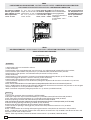
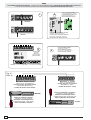
ZBKS
SCHEDA BASE -
MOTHERBOARD
- CARTE BASE -
GRUNDPLATINE
- TARJETA BASE
COMPOSANTS
PRINCIPAUX
1 Plaque à bornes
pour les branche-
ments
2 Fusible de ligne
3 Fusibles acces-
soires 2A
4 Branchement
carte radiofréquence
AF
5 LED de signali-
sation alimentation
à 24V
6 Boutons mise en
mémoire code radio
et programmation
des butées de fin de
course
7 Dip-switch
"sélection fonction"
8 Trimmer
AP.PARZ.: Réglage
Ouverture partielle
9 Trimmer TCA:
Réglage Temps de
fermeture automati-
que
10 LED de signali-
sation code radio et
programmation
encoder.
HAUPTKOMPONENTEN
1 Anschluss-
Klemmenleiste
2 Sicherung Lei-
tungs
3 2A-Sicherungen
Zubehörs
4 Steckanschluß
Funkfrequenze-
Platine AF
5 LED Kontrolleuch-
te für Stromversor-
gung mit 24V
6 Knöpfe zum
Abspeichern der
Radiocodes und zur
Programmierung vom
Endanschlag
7 "Funktionswahl"
dip-switch
8 Trimmer
AP.PARZ.: Einstel-
lung Teilöffnung
9 Trimmer TCA:
Einstellung Zeitein-
stellung Schließauto-
matik
10 LED Kontrolleuch-
te zur Anzeige von
Radiocode und
Encoder-Programmie-
rung.
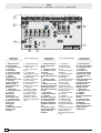
COMPONENTI
PRINCIPALI
1 Morsettiere di
collega mento
2 Fusibile di linea
3 Fusibili
accessori 2A
4 Innesto scheda
radiofrequenza AF
5 LED di
segnalazione
alimentazione a 24V
6 Pulsanti
memorizzazione
codice radio /
programmazione
finecorsa
7 Dip-switch
"selezione funzioni"
8 Trimmer
AP.PARZ.:
regolazione
apertura parziale
9 Trimmer TCA:
regolazione tempo
di chiusura
automatica
10 LED di
segnalazione codice
radio e prog.
encoder.
COMPONENTES
PRINCIPALES
1 Caja de bornes
para las conexiónes
2 Fusible de linea
3 Fusibles
accesorios 2A
4 Conexión tarjeta
radiofrecuencia AF
5 Indicador lumi-
noso de
alimentación de 24V
6 Botones de
memorización del
código radio y
programación de
final de carrera
7 Dip-switch
"seleción función"
8 Trimmer
AP.PARZ.:
Regulación Apertura
parcial
9 Trimmer TCA:
Regulación cierre
automático
10 Indicador lumi-
noso código radio y
programación
codificador.
MAIN COMPONENTS
1 Terminal block for
external connections
2 Line fuse
3 2A accessories
fuses
4 Socket AF
radiofrequency board
5 24V power-supply
signalling LED
6 Radio-code save
and limit-switch
programming buttons
7 "Function
selection" dip-switch
8 Trimmer
AP.PARZ.: Partial
opening djustment
9 Trimmer TCA:
automatic closing
time adjustment
10 Radio-code and
encoder-programming
LED.

-7-
10 11 TS 1 2 3 3P 4 5 7
2
MOT
N.O.
N.C.
C.
+
-
+
-
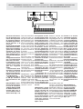
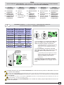
Consente alla centra-
lina di verificare l'effi-
cienza dei dispositivi
di sicurezza (fotocel-
lule) dopo ogni coman-
do di apertura o di
chiusura.
Un'eventuale anomalia
delle fotocellule è iden-
tificata con un lampeg-
gio del led sul quadro
comando, di conse-
guenza annulla qual-
siasi funzione del ra-
diocomando e del pul-
sante.
Collegamento elettrico
per il funzionamento
del test di sicurezza.
I trasmettitori e i rice-
vitori delle fotocellule
devono essere colle-
gati nel seguente
modo:
- il trasmettitore della
fotocellula collegato
sui morsetti TS-10,
mentre il ricevitore col-
legato sui morsetti 10-
11 (vedi disegno)
- selezionare il dip 13
in ON per attivare il
funzionamento del
test.
IMPORTANTE: Quan-
do si esegue la funzio-
ne test di sicurezza,
VERIFICARE che NON
CI SIANO PONTI tra i
contatti 2-CX, 2-C1 e,
se non utilizzati, esclu-
derli tramite dip 7 e 8.
The control unit will now
check the safety sys-
tem (photocells) every
time an opening or clos-
ing command is given.
If a photocell malfunc-
tions, a LED will flash
on the control panel,
and the radio transmit-
ter and the control
pushbutton will be de-
activated.
Electrical connections
required for safety test
function.
Photocell lamps and
sensors must be con-
nected as follows:
- connect the photocell
sensor across termi-
nals TS-10. Connect
the photocell lamp
across terminals 10-11
(see diagram);
- move dip switch 13 to
ON, which will activate
the test function.
IMPORTANT: When
the safety test is ena-
bled, CHECK that
THERE ARE NO
JUMPERS between
contacts 2-CX, 2-C1
and, if not being used,
exclude them using dip
switches 7 and 8.
Permite a la central
comprobar la eficien-
cia en los dispositi-
vos de seguridad (fo-
tocélulas) después de
cada comando de
apertura y cierre. Una
posible anomalía de
las fotocélulas se in-
dica a través de una
luz parpadeante del
LED en el cuadro de
mando y, por lo tanto,
se anula cualquier fun-
ción del transmisor y
de la tecla.
Conexión eléctrica
para el funcionamien-
to de las pruebas de
seguridad.
Los transmisores y los
receptores de las fo-
tocélulas deben estar
conectados de la si-
guiente manera:
- el transmisor de la
fotocélula conectado
a los bornes TS-10, el
receptor a los bornes
10-11 (ver dibujo);
- seleccionar el dip 13
en ON para activar el
funcionamiento de la
prueba.
IMPORTANTE: Al
activarse la función
test de seguridad,
CONTROLAR que
NO HAYA PUENTES
entre los contactos
2-CX, 2-C1 y, si no
se utilizan, inhabili-
tarlos mediante los
dip 7 y 8.
Dadurch besteht die
Möglichkeit, die Leis-
tungsfähigkeit der Si-
cherheitsvorrichtungen
(Lichtschranken) nach
jeder Öffnungs- und
Schließsteuerung zu
überprüfen.
Bei eventuell auftreten-
den Betriebsstörungen
der Lichtschranken
leuchtet die entspre-
chende LED auf dem
Steuergerät auf und jede
Funksender- und
Drucktaster-Funktion
wird automatisch annul-
liert.
Elektrischer Anschluß
für die Sicherheitstest-
Funktion.
Die Sender und Emp-
fänger der Lichtschran-
ken folgendermaßen an-
schließen:
- Lichtschrankensender
auf den Klemmen TS-
10, Empfänger auf den
Klemmen 10-11 (siehe
Abbildung)
-Dip-Switch 13 zur Akti-
vierung der Sicherheits-
test-Funktion auf ON
stellen.
ACHTUNG: Wenn die
Funktion Sicherheits-
test gestartet wird, muß
KONTROLLIERT wer-
den, daß es zwischen
den Kontakten 2-CX und
2-C1 KEINE BRÜCKEN
GIBT. Falls die Kontak-
ten nicht verwendet
werden, müssen Sie mit
Dip 7 und 8 ausge-
schlossen werden.
Cela permet au boî-
tier de vérifier le bon
fonctionnement des
dispositifs de sécuri-
té (photocellules)
aprés chaque com-
mande d'ouverture ou
de fermeture. Les
éventuelles anoma-
lies des photocellu-
les sont signalées par
un clignotement de la
led sur l'armoire de
commande, et la con-
séquente annulation
de toute fonction de
l'émetteur et du bou-
ton-poussoir.
Branchement électri-
que pour le fonction-
nement du test de sé-
curité.
Les émetteurs et les
récepteurs des pho-
tocellules doivent être
branchés de la maniè-
re suivante:
- l'émmetteur de la
photocellule sur le
bornes TS-10, celui du
récepteur sur les bor-
nes 10-11 (voir des-
sin);
- mettre le dip-switch
13 sur ON pour acti-
ver le fonctionnement
du test.
IMPORTANT: Quand
on active la fonction
test de sécurité, VE-
RIFIER qu'il N'Y A
PAS DE PONTS entre
les contacts 2-CX, 2-
C1 et, s'ils ne sont pas
utilisés, les exclure à
l'aide des interrup-
teurs à positions mul-
tiples 7 et 8.
ZBKS
TEST FUNZIONAMENTO FOTOCELLULE -
PHOTOCELL FUNCTION TEST
-TEST FONCTIONNEMENT PHOTOCELLULES
TEST FÜR DAS FUNKTIONIEREN DER LICHTSCHRANKEN
- TEST FUNCIONAMIENTO FOTOCELULAS

-8-
L1 L2
U V W E EX
10 11 TS 1 2 3 3P 4 5 7
2
MOT
FC FA F
2 C1 CX B1
B
U
W
V
L1
L2
10
5
E
W
E
EX
+10
-11
1
2
2
3
2
7
M
ZBKS
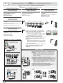
COLLEGAMENTI ELETTRICI -
ELECTRICAL CONNECTIONS -
BRANCHEMENTS ÉLECTRIQUES
ELEKRISCHE ANSCHLÜSSE - CONEXIONES ELÉCTRICAS
LAMPADA CORTESIA
COURTESY LIGHT
LAMPE PASSAGE
TORBELEUCHTUNG
LUZ DE CORTESIA
U
LAMPADA CICLO
CYCLE LAMP
LAMPE CYCLE
BETRIEBSZYKLUS-
ANZEIGELEUCHTE
LAMPARA CICLO
Ex
E
WV
max 60 Watt
ON
16 ON
17 OFF
ON
17 ON
16 OFF
Alimentazione 230V (a.c.)
power input 230V (a.c.)
Alimentation 230V (a.c.)
Stromversorgung 230V (a.c.)
Alimentación 230V (a.c.)
Motore 230V (a.c.)
motor 230V (a.c.)
Moteur 230V (a.c.)
Motor 230V (a.c.)
Motor 230V (a.c.)
Lampada spia (24V-3W) - cancello aperto
(24V-3W) gate-opened signal lamp
Lampe-témoin (24V-3W) portail ouvert
Signallampe (24V-3W) offenes Tor
Lámpara indicadora (24V-3W) puerta abierta
Uscita 230V (a.c.) in movimento (es.lampeggiatore 25W)
output 230V (a.c.) in motion (e.g. 25W flashing light)
Sortie 230V (a.c.) en mouvement (ex. branchement clignotant 25W)
Ausgang 230V (a.c.) in Bewegung (z.B. Blinker-Anschluß 25W)
Salida 230V (a.c.) en movimento (p.ej. lámpara intermitente 25W)
Lampada ciclo o lampada di cortesia 230V (a.c.)
Cycle lamp or courtesy light 230V (a.c.)
Lampe cycle ou lampe passage 230V (a.c.)
Betriebszyklus-Anzeigeleuchte oder Torbeleuchtung
230V (a.c.)
Lámpara ciclo luz de cortesía 230V (a.c.)
Alimentazione accessori 24V a.c. (max. 20W)
24V a.c. powering accessories (max 20W)
Alimentation accessoires 24V c.a. (max. 20W)
Zubehörspeisung 24V Wechselstrom (max 20W)
Alimentación accesoios a.c. 24V (max. 20W)
Pulsante stop (N.C.)
Pushbutton stop (N.C.)
Bouton-poussoir arrêt (N.F.)
Stop-Taste (N.C.)
Pulsador de stop (N.C.)
Pulsante apre (N.O.)
Pushbutton opens (N.O.)
Bouton-possoir ouverture (N.O.)
Taste Öffnen (N.O.)
Pulsador de apertura (N.O.)
Contatto radio e/o pulsante per comando (vedi dip-switch 2-3 el.funzioni)
Contact radio and/or button for control (see dip-switch 2-3 function election)
Contact radio et/ou poussoir pour commande (dip-switch 2-3 sel.fonction)
Funkkontakt und/oder Taste Steuerart (dip-switch 2-3 Funktionswahl)
Contacto radio y/o pulsador para mando (dip-switch 2-3 seleción fonción)
LAMPADA CORTESIA
COURTESY LIGHT
LAMPE PASSAGE
TORBELEUCHTUNG
LUZ DE CORTESIA
LAMPADA CICLO
CYCLE LAMP
LAMPE CYCLE
BETRIEBSZYKLUS-
ANZEIGELEUCHTE
LAMPARA CICLO

-9-
2
4
2
C1
2
CX
2MOT
F
FA
F
FC
B1
B2
2
3P
Pulsante per apertura parziale (N.O.)
Open button (N.O.) for partial aperture
Bouton-poussoir d'ouverture (N.O.) pour ouverture partial
Taste Öffnen (Arbeitskontakt) für TeilÖffnung
Pulsador de apertura (N.O.) para aperture parcial
Pulsante chiude (N.O.)
Close button (N.O.)
Poussoir de fermeture (N.O.)
Taste Schließen (Arbeitskontakt)
Pulsador de cierre (N.O.)
Contatto (N.C.) di «riapertura durante la chiusura»
Contact (N.C.) for «re-aperture during closure»
Contact (N.F.) de «réouverture pendant la fermeture»
Kontakt (Ruhekontakt) Wiederöffnen beim Schliessen
Contacto (N.C.) para la apertura en la fase de cierre
Contatto (N.C.) di «richiusura durante la apertura»
(selezionare dip 8 in OFF- 9 in OFF)
"Re-close during opening" contact (N.C.) (Set Dip 8 to OFF - 9 to OFF)
Contact (N.F.) de "réfermeture durant l'ouverture"
(sélectionner dip 8 sur OFF - 9 sur OFF)
NC-Kontakt für "erneutes Schließen beim Öffnen"
(dazu Dip 8 auf OFF und Dip 9 auf OFF stellen)
Contacto (N.C.) de "cierre durante la apertura"
(seleccione el dip 8 en OFF - 9 en OFF)
Contatto (N.C.) "stop parziale" (selezionare dip 8 in OFF- 9 in ON)
"Partial stop" contact (N.C.) (Set Dip 8 to OFF - 9 to ON)
Contact (N.F.) "stop partiel" (sélectionner dip 8 sur OFF - 9 sur ON)
NC-Kontakt für "Teilstop" (dazu Dip 8 auf OFF und Dip 9 auf ON stellen)
Contacto (N.C.) de "parada parcial" (seleccione el dip 8 en OFF - 9 en ON)
Collegamento antenna
Antenna connection
Connexion antenne
Antennenanschluß
Conexión antena
Uscita contatto (N.O.) Portata contatto: 5A a 24V d.c.
Contact output (N.O.) Resistive load: 5A 24V d.c.
Sortie contact (N.O.) Portée contact: 5A a 24V c.c.
Ausgang Arbeitskontakt Stromfestigkeit: 5A bei 24V Gleichstrom
Salida contacto (N.O.) Carga resistiva: 5A a 24V d.c.
Uscita per comando di n.2 motori abbinati
Connection for simultaneous control of 2 combined motors
Sortie pour commande simultanée de 2 moteurs accouples
Ausgang zur gleichzeitigen Steuerung von 2 parallelgeschalteten Motoren
Salida para el mando simultáneo de n.2 motores acoplados
Collegamento (N.C.) finecorsa apre
Connection (N.C.) limit switch opens
Connexion (N.F.) fin de course ouverture
Anschluß (N.C.) Endschallter Öffnung
Conexión (N.C.) fin de carrera apertura
Collegamento (N.C.) finecorsa chiude
Connection (N.C.) limit switch closes
Connexion (N.F.) fin de course fermeture
Anschluß (N.C.) Endschallter Schließung
Conexión (N.C.) fin de carrera cierre

-10-
DIP-SWITCHES (1-10)
1 2345678910
ON
11 12 13
ON
0
2412
123 4
FRENO
SPUNTO
ZBKS
LIMITATORE DI COPPIA MOTORE -
MOTOR TORQUE LIMITER
- LIMITEUR DE COUPLE MOTEUR
DREHMOMENTBEGRENZER DES MOTORS -
LIMITADOR DE PAR MOTOR
Per variare la coppia
motore, spostare il fa-
ston indicato su una
delle 4 posizioni;
1 min - 4 max.
To vary the motor
torque, move the indi-
cated faston to one of
the four positions:
1=min, 4=max
Para variar el par mo-
tor, desplazar el fas-
ton indicado hasta una
de las 4 posiciones;
1 mín. - 4 máx.
Zur Änderung des
Motor-Drehmoments
den angegebenen
Faston auf eine der 4
Stellungen
positionieren: 1 min. -
4 max.
Pour varier le couple
du moteur, déplacer
le connecteur indiqué
sur l'une des 4 posi-
tions; 1 min. - 4 max.
1 ON Funzione chiusura automatica attivata;
(1 OFF disattivato)
2 ON Funzione "apre-stop-chiude-stop" con pulsante (2-7) e radiocomando (scheda AF inserita) attivato;
2 OFFFunzione "apre-chiude" con pulsante (2-7) e radiocomando (scheda AF inserita) attivato;
3 ON Funzione "solo apertura" con radiocomando (scheda AF inserita) attivato;
(3 OFF disattivato)
4 ON Funzione a "uomo presente" (esclude la funzione del radiocomando) attivato; (4 OFF disattivato)
5 ON Prelampeggio in apertura e chiusura attivato; (5 OFF disattivato)
6 ON Funzione rilevazione ostacolo attivato; (6 OFF disattivato)
7 OFFFunzione di riapertura in fase di chiusura (collegare il dispositivo di sicurezza sui morsetti 2-C1) attivata;
(7 ON disattivato)
8 OFF - 9 OFFFunzione di richiusura in fase di apertura (collegare il dispositivo di sicurezza sui morsetti 2-CX) attivata;
8 OFF - 9 ONFunzione di stop parziale (collegare il dispositivo di sicurezza sui morsetti 2-CX) attivato; se non vengono
utilizzati i dispositivi su 2-CX, posizionare il dip 8 in ON
10 OFF
Funzione di stop totale (collegare pulsante su 1-2) attivato; (10 ON disattivato)
1 ON Function automatic closure enabled; (1 OFF disabled)
2 ON "open-stop-close-stop" function with button (2-7) and radio control (AF board inserted) enabled;
2 OFF "open-close "function with button (2-7) and radio control (AF board inserted) enabled;
3 ON "only opening" function with radio control (AF board inserted) enabled;
4 ON "Operator present" operation (radio remote control is deactivated when function is selected) enabled; (4 OFF disabled)
5 ON Pre-flashing (opening and closing) enabled; (5 OFF disabled)
6 ON Function obstacle detection device enabled; (6 OFF disabled)
7 OFF Function re-opening in closing phase (connect the safety device on terminals 2-C1) enabled;
(7 ON disabled)
8 OFF - 9 OFFFunction of re-closing while opening (connect the safety device on terminals 2-CX) enabled;
8 OFF - 9 ONPartial stop function (connect the safety device on terminals 2-CX) enabled; if the devices on the 2-CX
terminals are not used, se Dip 8 to ON
10 OFF -Total stop function (connect the button onto terminals 1-2) enabled; (10 ON disabled)
ITALIANO
ENGLISH
ZBKS
SELEZIONI FUNZIONI -
SELECTION OF FUNCTIONS
- SÉLECTION FONCTIONS-
FUNKTIONSWAHL
SELECCIÓN DE LAS FUNCIONES

-11-
1 ON Fonction fermeture automatique activé; (1O FF éteinte)
2 ON Fonction "ouvre-stop-ferme-stop" avec bouton (2-7) et commande-radio (carte AF insérée) activé;
2 OFF Fonction "ouvre-ferme" avec bouton (2-7) et commande-radio (carte AF insérée) activé;
3 ON Fonction "soulement ouverture" avec commande-radio (carte AF insérée) activé;
4 ON Fonctionnement avec "homme mort" (exclut la fonction radiocommande) activé; (4 OFF éteinte)
5 ON Preclignotement pandant la phase d'ouverture et de fermeture activé; (5 OFF éteinte)
6 ON Fonction dispositif de détection d'obstacle activé; (6 OFF ét.)
7 OFF Fonction réouverture en phase de fermeture (relier le dispositif de sécuritè aux bornes 2-C1) activé; (7 ON éteinte)
8 OFF - 9 OFF Fonction de réfermeture en phase d'ouverture (relier le dispositif de sécuritè aux bornes 2-CX) activé;
8 OFF - 9 ON Fonction de stop partiel (relier le dispositif de sécuritè aux bornes 2-CX) activé; si les dispositifs sur 2-CX
ne sont pas utilisés, positionner le dip 8 sur ON
10 OFF
Fonction de stop total (relier le bouton sur les bornes 1-2) activé
FRANÇAIS
1 ON Función cierre automático activado; (1 OFF desactivado)
2 ON Función "abrir-stop-cerrar-stop" con botón (2-7) y radiocontrol (tarjeta AF conectada) activado;
2 OFF Función "abrir-cerrar" con botón (2-7) y radiocontrol (tarjeta AF conectada) activado;
3 ON Función "solo apertura" con radiocontrol (tarjeta AF conectada) activado;
4 ON Funcionamiento a "hombre presente" (escluye la función del mando de radio) activado; (4 OFF desactivado.)
5 ON Pre-intermitencia en la fase de apertura y cierre activado; (5 OFF desactivado.)
6 ON Función de detección del obstáculo activado; (6 OFF desactivado)
7 OFF Función de reapertura en la fase de cierre (conecte el dispositivo de seguridad a los bornes 2-C1) activado; (7
ON desactivado)
8 OFF - 9 OFF Función de recierre durante la apertura (conecte el dispositivo de seguridad a los bornes 2-CX) activado;
8 OFF - 9 ON Función de parada parcial (conecte el dispositivo de seguridad a los bornes 2-CX) activado; si no utiliza
los dispositivos en 2-CX, coloque el dip 8 en ON
10 OFF Función de parada total (conecte el botón a los bornes 1-2) activado (10 ON desactivado)
ESPANIOL
1 ON Funktion Schließautomatik zugeschaltet; (1 OFF ausgeschlossen)
2 ON Funktion "Öffnen-Stop-Schließen-Stop" mit Druckknopf (2-7) und Fernsteuerung (Karte AF eingesteckt) zugeschal-
tet;
2 OFF Funktion "Öffnen-Schließen" mit Druckknopf (2-7) und Fernsteuerung (Karte AF eingesteckt) zugeschaltet;
3 ON Funktion "nur Öffnen" mit Fernsteuerung (Karte AF eingesteckt) zugeschaltet;
4 ON Bedienung vom "Steuerpult" (bei Wahl dieser Betriebsart wird die Funkfernsteuerung ausgeschlossen) zugeschaltet;
(4 OFF ausgeschlossen)
5 ON Vorblinken beim Öffnen und Schlie0 ßen zugeschaltet; (5 OFF ausgeschlossen)
6 ON Funktion Hindemisaufnahme zugeschaltet; (6 OFF ausgeschlossen)
7 OFF Wiederöffnen beim Schließen zugeschaltet (schließen Sie die Sicherheitsvorrichtung an die Klemmen 2-C1 an)
zugeschaltet; (7 ON ausgeschlossen)
8 OFF - 9 OFF Funktion für erneutes Schließen während dem Öffnen zugeschaltet (schließen Sie die Sicherheitsvorrich-
tung an die Klemmen 2-CX an)
8 OFF - 9 ON Funktion für teilstop zugeschaltet (schließen Sie die Sicherheitsvorrichtung an die Klemmen 2-CX an); Wenn
die Sicherungen nicht an die Klemmen 2-CX angeschlossen werden, die Dip 8 auf ON stellen
10 OFF Funktion vollständiger Stop (den Druckknopf an die Klemmen 1-2 anschließen) zugeschaltet;
DEUTSCH

-12-
ZBKS
SELEZIONI FUNZIONI -
SELECTION OF FUNCTIONS
- SÉLECTION FONCTIONS -
FUNKTIONSWAHL
SELECCIÓN DE LAS FUNCIONES
DIP-SWITCHES (11-20)
910 11 12 13 14 15 16 17 18 19 20
ON
11 OFF Fonction
"Slave" désactivée
(à n'activer que pour
le branchement
accouplé, voir page
13);
12 ON Fonction
d'ouverture partielle
(la fermeture auto-
matique est fixe à
8") activé
12 OFF Fonction
d'ouverture partielle
(la fermeture auto-
matique est réglable
au moyen du trim-
mer, si elle est
enclenchée) activé;
13 ON Activation du
test de sécurité pour
le contrôle du bon
fonctionnement des
photocellules (voir
pag. 7) activé; (13
OFF désactivée)
14 OFF Fonction
"Master" désactivée
(à n'activer que pour
le branchement
accouplé, voir page
13);
15 OFF désactivée
16 ON Fonction
lampe d'éclairage
activé; (16 OFF
désactivée)
17 ON Fonction
lampe cycle activé;
(17 OFF désactivée)
18 Non connecté
19 Non connecté
20 Non connecté
11 OFF Slave-Funktion
ausgeschlossen (wird nur
für kombinierte Anschlüs-
se zugeschaltet, siehe
S. 13);
12 ON Funktion teilweises
Öffnen zugeschaltet (die
Zeit für das automatische
Schließen ist mit 8
Sekunden vorgegeben)
12 OFF Funktion teilwei-
ses Öffnen zugeschaltet
(die Zeit für das automati-
sche Schließen kann mit
dem Timer eingestellt
werden, falls vorhanden)
13 ON Aktivierung der
Sicherheitstest-Funktion
zur Überprüfung der
Lichtschranken-Leistung-
keit (siehe Seite 7)
zugeschaltet; (13 OFF
ausgeschlossen)
14 OFF Master-Funktion
ausgeschlossen (wird nur
für kombinierte Anschlüs-
se zugeschaltet, siehe
S. 13);
15 OFF ausgeschlossen
16 ON Funktion Torbe-
leuchtung zugeschaltet;
(16 OFFausgeschlossen)
17 ON Funktion Beleuch-
tung Zyklus zugeschaltet;
18 nicht angeschlossen
19 nicht angeschlossen
20 nicht angeschlossen
FRANÇAIS
DEUTSCH
11 OFF Funzione
"slave" disattivata
(da attivare solo
per collegamento
abbinato, vedi pag.
13);
12 ON Funzione di
apertura parziale
(la chiusura auto-
matica è fissa a 8")
attivata;
12 OFF Funzione
di apertura parzia-
le (la chiusura
automatica è
regolabile median-
te trimmer, se
inserita) attivata;
13 ON Funzione
del test di sicurez-
za per la verifica
dell'efficenza delle
fotocellule (vedi
pag. 7) attivato; (13
OFF disattivato)
14 OFF Funzione
"master" disattiva-
ta (da attivare solo
per collegamento
abbinato, pag. 13);
15 OFF disattivato
16 ON Funzione
lampada di corte-
sia attivata;
(16 OFF disattivata)
17 ON Funzione
lampada ciclo atti-
vata;
(17 OFF disattivata)
18 Non connesso
19 Non connesso
20 Non connesso
11 OFF "Slave"
function deactivated
(to active only for
coupled connection,
see page 13);
12 ON Partial opening
function (automatic
closing is fixed at 8
seconds) enabled;
12 OFF Partial open-
ing function
(automatic closing is
adjusted with the
trimmer, if inserted)
enabled;
13 ON Activates
safety test that
checks the photocells
proper operation (see
pag. 7) enabled; (13
OFF disabled)
14 OFF "Master"
function deactivated
(to active only for
coupled connection,
see page 13);
15 OFF disabled
16 ON Courtesy light
function enabled;
(16 OFF disabled)
17 ON Lamp cycle
function enabled;
(17 OFF disabled)
18 Not connected
19 Not connected
20 Not connected
11 OFF Función
"slave" desactivada
(se activa sólo para
la conexión combi-
nada, véase pág. 13);
12 ONFunción de
apertura parcial (el
cierre automático está
regulado en 8") acti-
vado;
12 OFF Función de
apertura parcial (el
cierre automático se
puede regular por
medio del trimmer,
sin está conectado)
activado;
13 ONActivación del
puebra de seguridad
para comprobar la
eficiencia de los
fotocélulas (ver pág.
7) activado; (13 OFF
desactivado)
14 OFF Función
"master" desactiva-
da (se activa sólo
para la conexión
combinada, véase
pág. 13);
15 OFF desactivado
16 ONFunción luz
de cortesia activado;
(16 OFF desactivada)
17 ONFunción
lámpara ciclo activa-
do; (17 OFF
desactivada)
18 No conectado
19 No conectado
20 No conectado
ENGLISH
ITALIANO
ESPANIOL

-13-
BA
ZBKS
COLLEGAMENTO PER 2 MOTORI ABBINATI -
CONNECTIONS FOR 2 COMBINED MOTORS
CONNEXIONS POUR 2 MOTEURS ACCOUPLÉS
ANSCHLUSSE FÜR 2 PARALLELGESCHALTETEN MOTOREN
- CONEXIÓN PARA 2 MOTORES ACOPLADOS
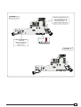
- Coordinare il senso
di marcia dei motori-
duttori A e B, modifi-
cando la rotazione del
motore B;
- Stabilire tra A e B il
motore master (o pi-
lota), posizionare il
dip-switch 14 in ON
sulla scheda coman-
do. Per "master" s'in-
tende il motore che
comanda ambedue i
cancelli, mentre sulla
scheda comando del
2° motore posiziona-
re il dip 11 in ON per
renderlo pilotato (sla-
ve-Fig.1).
- Assicurarsi che sia
inserito il ricevitore
radio solo sul quadro
MASTER (Fig.2);
-Eseguire solo sulla
morsettiera MASTER
i collegamenti elettri-
ci e le selezioni predi-
sposte normalmente
(Fig.3);
- Eseguire tra le mor-
settiere i collegamen-
ti come da «figura A»,
e accertarsi che la
chiusura automatica
sia attivata nel moto-
re "master" e disatti-
vata nel 2° motore;
-Assicurarsi che tutti i
dip del quadro del 2°
motore siano disatti-
vati (OFF) tranne il dip
11 (Fig.4).
Importante: regolare
i finecorsa dei motori
in modo che, l'anta
del motore MASTER
arrivi in chiusura dopo
della SLAVE.
- Match the directions in
which gear motors A and B
rotate by changing the di-
rection in which motor B ro-
tates ;
- Set the master (or pilot)
motor between A and B by
setting dip-switch 14 to ON
on the control board. "Mas-
ter" refers to the motor that
controls both the gates. On
the control board of the 2
nd
motor, set dip-switch 11 to
ON to make it the "slave"
(Fig.1).
-Make sure that the radio
receiver is activated only on
the MASTER board Fig.2;
-Wire the electrical con-
nections and the normally
used selections only on the
MASTER terminal board
Fig.3;
-Wire the electrical con-
nections between the termi-
nal boards, as shown in the
«figure A», and make sure
that the automatic closing
function is enabled for the
"master" motor and disabled
for 2
nd
motor;
- Make sure that all the dip-
switches on the board of the
2
nd
motor are (OFF), except
for dip 11 (Fig.4).
Important: set the motor's
stop limits so that the MAS-
TER motor's door reaches
closing position after the
SLAVE motor's door.
- Coordinar el sentido
de marcha de los
motorreductores A y
B, modificando la ro-
tación del motor B;
-Establezca el motor
master (o piloto) entre
los motores A y B, co-
locando el dip-switch
14 en ON en la tarjeta
de mando. “Master”
significa que el motor
acciona ambas puer-
tas. En la tarjeta de
mando del 2° motor,
coloque el dip 11 en
ON para que pueda
ser controlado (slave
- Fig.1).
- Cerciórese de que el
radiorreceptor esté
conectado sólo en el
cuadro MASTER
(Fig.2);
-Realice las conexion-
es eléctricas y las
selecciones normal-
mente reguladas, sólo
en el tablero de bor-
nes MASTER (Fig.3);
- Efectuar entre las
cajas de bornes las
conexions como indi-
cado en la «figura A»,
y asegurarse que el
cierre automático esté
activado en el motor
"master" y desactiva-
do en el 2° motor;
- Cerciórese de que
todos los dip del cua-
dro del 2° motor estén
desactivados (OFF),
excepto el dip 11
(Fig.4).
Importante: regule los
microinterruptores de
tope de los motores
de manera que la hoja
del motor MASTER se
cierre después que la
de SLAVE.
-Coordonnerle le sens
de marche des
motoreducteurs A et
B en modifiantle sens
de rotation du moteur
B;
-Fixer entre A et B le
moteur master (ou pi-
lote) en positionnant
le dip-switch 14 sur
ON sur la fiche com-
mande. Par “master”
il s’agit du moteur qui
commande les deux
grilles, tandis que sur
la fiche de comman-
de du 2sd moteur po-
sitionner le dip 11 sur
ON pour qu’il soit pi-
loté (slave - Fig.1).
-S'assurer que tous
les récepteur radio est
bien introduit seule-
ment sur le pupitre
MASTER (Fig.2);
-Effecteur seulement
sur la barrette de con-
nexion MASTER les
liaisons électriques et
les sélections normal-
ment prédisposées
(Fig.3);
-Effectuer les
branchements entre
les plaques à bornes
de la façon indiquée
sur la «figure A», et
contrôler que la fonc-
tion de fermeture au-
tomatique est activée
pour le moteur "mas-
ter" et désactivée pour
le 2ème moteur.
-S'assurer que tous
les dip du pupitre du
2sd moteur sont
éteints (OFF) à
l'exception du dip 11
(Fig.4).
Important: régler les
interrupteurs de fin de
course des moteurs
pour que la porte du
moteur MASTER
(principal) arrive en
fermeture après celle
SLAVE (auxiliaire).
-Die Gangrichtung der Ge-
triebemotoren A und B durch
Drehrichtu- ngsõnderung
des Motores B koordinieren;
-Legen Sie fest, welcher der
Motoren A und B der Master-
Motor (übergeordnet) sein
soll. Stellen Sie dazu den
Dip-Switch 14 auf der Steu-
erungskarte auf ON. Unter
Master-Motor wird der Mo-
tor verstanden, der beide
Tore steuert. Auf der Steue-
rungskarte des anderen Mo-
tors muß der Dip-Switch 11
auf ON gestellt werden, so
daß er eine untergeordnete
Funktion (Slave-Motor)
bekommt (Abb.1).
-Kontrollieren Sie, daß der
Radioempfänger nur auf der
MASTER-Schalttafel einge-
steckt ist (Abb.2);
-Führen Sie nur am MAS-
TER Klemmbrett die elektri-
schen Anschlüsse und die
normalerweise durchgeführ-
ten Voreinstellungen aus
(Abb.3);
- Die Verbindungen zwisch-
en den beiden Klemmleisten
der «Abbildung A»
entsprechend ausführen,
daß die Schließautomatik-
funktion auf dem "Master-
motor" zugeschaltet und auf
dem 2. Motor ausgeschaltet
ist.
-Kontrollieren Sie, daß alle
Dip-Switch auf der Schalt-
tafel des untergeordneten
Motor auf OFF stehen, mit
Ausnahme vom Dip 11, der
auf ON stehen muß
(Abb.4).Achtung: Stellen Sie
die Endanschläge der Moto-
ren so ein, daß der Torflügel
vom MASTER-Motor nach
dem vom SLAVE-Motor
schließt.

-14-
1
1211 13 14 15 16 17 18 19 20O
N
9
10
«MASTER»
1211 13 14 15 16 17 18 19 20O
N
910
«SLAVE»
«MASTER»
10 11 TS 1 2 3 3P 4 5 7
2
MOT
10 11 TS 1 2 3 3P 4 5
7
«Fig. A»
«Abb. A»
1211 13 14 15 16 17 18 19 20O
N
2
1 345678910O
N
1211 13 14 15 16 17 18 19
20
O
N
2
1 34567
8910
O
N
«SLAVE»
ZBKS
COLLEGAMENTO PER 2 MOTORI ABBINATI -
CONNECTIONS FOR 2 COMBINED MOTORS
-
CONNEXIONS
POUR
2
MOTEURS
ACCOUPLÉS
ANSCHLUSSE
FÜR
2
PARALLELGESCHALTETEN
MOTOREN
-CONEXIÓN PARA 2 MOTORES ACOPLADOS
ENCODER
AF
2
4
1211 13 14 15 16 17 18 19 20O
N
910
SETTAGGIO OBBLIGATORIO
OBLIGATORY SETTING
INSTALLATION OBLIGATOIRE
DAS SETUP IST OBLIGATORISCH
REGULACION OBLIGATORIA
10 11 TS 1 2 3 3P 4 5 7
2
MOT
21 345678910O
N
1211 13
14
15
16 17 18 19
20
O
N
3
FUNZIONI -
FUNCTIONS
- FONCTIONS
- FUNKTIONEN -
FUNCIONES
REGOLAZIONI
SETTING
RÉGLAGES
EINSTELLUNGEN
REGULACIONES
SCHEDA RADIOFREQUENZA "AF"
"AF" RADIO FREQUENCY BOARD
CARTE FREQUENCE RADIO "AF"
RADIOFREQUENZKARTE «AF»
TARJETA RADIOFRECUENCIA
SCHEDA BASE DEL MOTORE "MASTER"
"MASTER" MOTOR MAIN BOARD
CARTE DE BASE DU MOTEUR "MASTER"
BASISKARTE VOM MOTOR "MASTER"
TARJETA BASE DEL MOTOR «MASTER»
Morsettiera motore master
Master motor terminal block
Plaque à bornes du moteur master
Klemmbrett Mastermotor
Cuadro de bornes motor master
Chiusura automatica attivata
Automatic closure enabled
Fermeture automatique activé
Schließenautomatik zugeschaltet
Cierre automático activado
Chiusura automatica disattivata
Automatic closure disabled
Fermeture automatique éteinte
Schließenautomatik ausgeschlossen
Cierre automático desactivado
Morsettiera 2° motore
Motor 2° terminal block
Plaque à bornes du 2° moteur
Klemmbrett 2° Motor
Cuadro de bornes 2° motor

-15-
ENGLISH
PROCEDURE
A. insert an
AF card **.
B. encode
transmitter/s.
C. store code in the
motherboard.
FRANÇAIS
PROCEDURE
A. placer une carte
AF **.
B. codifier le/s
émetteur/s.
C. mémoriser la
codification sur
la carte base.
DEUTSCH
PROZEDUR
A. Stecken Sie eine
Karte AF **.
B. Codieren Sie den/
die Sender.
C. Speichern Sie die
Codierung auf der
Grundplatine.
ZBKS
INSTALLAZIONE DEL RADIOCOMANDO -
RADIO CONTROL INSTALLATION -
INSTALLATION DE LA RADIOCOMMANDE
INSTALLATION DER RADIOSTEUERUNG -
INSTALACIÓN DEL RADIOMANDO
ITALIANO
PROCEDURA
A. inserire una
scheda AF **.
B. codificare il/i
trasmettitore/i.
C. memorizzare la
codifica sulla
scheda base.
ESPANOL
PROCEDIMIENTO
A. introducir una
tarjeta AF **.
B. codificar el/los
transmisor/es.
C. memorizar la
codificación en
la tarjeta base.
La schedina AF deve essere inserita OBBLIGATORIAMENTE in assenza di tensione, perché la scheda madre la riconosce
solo quando viene alimentata
The AF board should ALWAYS be inserted when the power is off because the motherboard only recognises it when it is powered.
La carte AF doit OBLIGATOIREMENT être branchée en l’absence de tension car la carte mère ne la reconnaît que quand
elle est alimentée.
Vor Einschieben der Karte die Stromzufuhr UNBEDINGT abschalten, da die Erkennung durch die Hauptkarte nur über eine
Neueinschaltung ( nur durch Versorgung) erfolgt.
La tarjeta AF se debe montar OBLIGATORIAMENTE en caso de falta de corriente, porque la tarjeta madre la reconoce sólo
cuando está alimentada
SCHEDA BASE
MOTHERBOARD
CARTE DE BASE
BASISKARTE
TARJETA BASE
SCHEDA "AF"
"AF" BOARD
CARTE "AF"
KARTE «AF»
TARJETA «AF»
(**) Per trasmettitori con frequenza 433.92 AM (serie
TOP e serie TAM) bisogna, sulla relativa scheda
AF43S, posizionare il jumper come illustrato.
(**) On AM transmitters operating at 433.92 MHz
(TOP and TAM series), position the jumper
connection on circuit card AF43S as shown on
the sheet.
(**) Pour les émetteurs de fréquence 433.92 AM
(série TOP et série TAM) il faut positionner le pontet
sur la carte AF43S correspondante de la façon
indiquée.
(**) Bei Sendern mit einer Frequenz von 433.92
AM (Reihe TOP und Reihe TAM) ist der auf der
entsprechenden Platine AF43S befindliche
Jumper der Abbildung entsprechend zu
positionieren.
(**) Para transmisores con frecuencia 433.92 AM
(serie TOP y serie TAM) es necesario, en la tarjeta
corespondiente AF43S, colocar el jumper como se
indica
INSERIMENTO SCHEDA AF -
AF BOARD INSERTION
- NSTALLATION DE LA CARTE AF
EINSTECKEN DER KARTE AF
- MONTAJE DE LA TARJETA AF
A
AF
20
Frequenza/MHz
Frequency/MHz
Frequence/MHz
Frequenz/MHz
Frequencia/MHz
Scheda radiofrequenza
Radiofrequency board
Carte radiofréquence
Funkfrequenz-platine
Tarjeta radiofrecuencia
Tra sme tt it or e
Transmitter
Emmetteur
Funksender
Tra ns mi sor
FM 26.995 AF130 TFM
FM 30.900 AF150 TFM
AM 26.995 AF26 TOP
AM 30.900 AF30 TOP
AM 433.92 AF43S / AF43SM TAM / TOP
AM 433.92 AF43SR ATOMO
TOP TAM

-16-
PROCEDURA COMUNE DI CODIFICA
T262M-T264M-T2622M
T302M-T304M-T3022M
1.segnare un codice (anche per archivio)
2.inserire jumper codifica J
3.memorizzarlo
4.disinserire jumper J
STANDARD ENCODING PROCEDURE
T262M-T264M-T2622M
T302M-T304M-T3022M
1.assign a code (also on file)
2.connect encoding jumper J
3.register code
4.disconnect jumper J
PROCEDURE COMMUNE DE CODIFICATION
T262M-T264M-T2622M
T302M-T304M-T3022M
1.taper un code (également pour les
archives)
2.placer un cavalier de codification J
3.mémoriser le code
4.enlever le cavalier J
ANLEITUNGEN ZUR CODIERUNG
T262M-T264M-T2622M
T302M-T304M-T3022M
1.Ordnen Sie einen Code zu (auch für das
Archiv).
2.Schalten Sie den Codierungs-Jumper J ein.
3.Speichern Sie den Code.
4.Schalten Sie den Jumper J wieder aus.
PROCEDIMIENTO COMÚN DE CODIFICACIÓN
T262M-T264M-T2622M
T302M-T304M-T3022M
1.marcar un código (también para el
archivo)
2.conectar un jumper codificación J
3.registrar el código
4.desconectar jumper J
P1 P2
P3 P4
P1=CH1 - P2=CH2
P3=CH3 - P4=CH4
J
T264M - T304M
La prima codifica deve essere effettuata mantenendo i
jumper posizionati per i canali 1 e 2 come da fig. A; per
eventuali e successive impostazioni su canali diversi
vedi fig. B
The first encoding operation must be carried out whilst
keeping the jumpers positioned for channels 1 and 2 as
per fig. A; see fig. B for any subsequent settings on
different channels.
La première codification doit être effectuée en
maintenant les cavaliers en position pour les canaux 1 et
2, comme d'après la fig. A; pour des saisies successives
éventuelles sur des canaux différents, voir fig. B
Für die erste Codierung muß der Jumper auf den Kanälen
1 und 2 positioniert bleiben (siehe Abb. A). Für eventuelle
weitere oder spätere Einstellungen auf anderen Kanälen
halten Sie sich bitte an Abb. B.
La primera codificación tiene que efectuarse
manteniendo los jumper conectados para los canales 1 y
2 como se ilustra en la fig. A; para planteamientos
posteriores en canales distintos ver la fig. B
T262M - T302M
P1 P2
J
P1=CH1
P2=CH2
fig.
A
fig. B
P1=CH1 - P2=CH4
P1=CH1 - P2=CH3
P1=CH3 - P2=CH2
P1=CH3 - P2=CH4
P1 P2
T2622M - T3022M
2° codice/
codice
/codice/
codice
/codice
ON
OFF
P1
P2
P3=CH1
P4=CH2
J
1° codice/
codice
codice/
codice
/codice
P1=CH1
P2=CH2
J
premere in sequenza P1 o P2 per registrare il
codice; al decimo impulso un doppio suono
confermerà l'avvenuta registrazione
Press P1 or P2 in sequence in order to register
the code; at the tenth pulse, a double beep will
confirm that registration has occurred
appuyer en séquence sur P1 ou P2 pour
mémoriser le code; à la dixième impulsion, une
double sonnerie confirme que le code a été
mémorisé
Drücken Sie nacheinander P1 oder P2, um den
Code zu speichern. Nach dem zehnten Impuls
signalisiert ein doppelter Piepton, daß der Code
gespeichert worden ist.
oprimir repetidamente P1 ó P2 para registrar el
código; con el décimo impulso un doble
sonido señalará que el registro se ha
efectuado.
2.
J
ON
OFF
P1
P2
codice/
codice
/codice/
codice
/codice
1.
4.
J
P1=OFF
P2=ON
3.
TOP
QUARZATI
- QUARTZ
- AU QUARTZ
- QUARTZGENAUE
- CUARZO
ZBKS
CODIFICA TRASMETTITORI -
TRANSMITTER ENCODING
- CODIFICATION DES EMETTEURS
CODIERUNG DER SENDER
- CODIFICACIÓN TRANSMISORES
B

-17-
ZBKS
CODIFICA TRASMETTITORI -
TRANSMITTER ENCODING
- CODIFICATION DES EMETTEURS
CODIERUNG DER SENDER
- CODIFICACIÓN TRANSMISORES
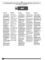
impostare il codice sul dip-switch C e il canale su D (P1=CH1 e
P2=CH2, impostazione di default)
set the code to dip-switch C and channel to D (P1=CH1 and P2=CH2,
default setting)
saisir le code sur le commutateur dip C et le canal sur D (P1=CH1 et
P2=CH2, saisie de défaut)
Stellen Sie den Code auf den Dip-Switch C und den Kanal auf D
(P1=CH1 und P2=CH2; Grundeinstellung).
plantear el código en el dip-switch C y el canal en D (P1=CH1 y
P2=CH2, planteamiento por defecto)
T432M - T312M
1 2 3 4 5 6 7 8 9 10
1 2 3 4
C
D
P1 P2
P2
CH1 CH2 CH3
CH4
P1
CH1 CH2 CH3
CH4
1 2 3 4 1 2 3 4 1 2 3 41 2 3 4
1 2 3 4 1 2 3 4 1 2 3 4 1 2 3 4
vedi istruzioni su confezione
see instructions on pack
voir instructions sur l'emballage
Siehe Anleitungen auf der Packung.
ver instrucciones en el embalaje
T432S / T432SA /T434MA
AT01 - AT02 - AT04
B
ATOMO
vedi foglio istruzioni inserito nella confezione
della scheda AF43SR
see instruction sheet inside the pack of
AF43SR circuit card
voir les instructions qui se trouve dans
l'emballage de la carte AF43SR
Siehe Anleitungen, die der Packung beiliegen
der Platine AF43SR
ver hoja de instrucciones adjunta en el
embalaje de la tarjeta AF43SR
vedi foglio istruzioni inserito nella
confezione
see instruction sheet inside the pack
voir la notice d'instructions qui se
trouve dans l'emballage
Siehe Anleitungen, die der Packung
beiliegen.
ver hoja de instrucciones adjunta en
el embalaje
T132
T134
T138
T152
T154
T158
T432
T434
T438
T434M - T314M
impostare solo il codice
set code only
ne saisir que le code
Stellen Sie nur den Code ein.
plantear sólo el código
P1=CH1
P2=CH2
P3=CH3
P4=CH4
1 2 3 4 5 6 7 8 9 10
C
P1 P2
P3 P4
TOP
TAM TFM

-18-
-Assicurarsi che il dip
15 sia in OFF (pro-
grammazione fine-
corsa disattivata);
-Tenere premuto il ta-
sto "CH1" sulla sche-
da base (il led di se-
gnalazione lampeg-
gia), con un tasto del
trasmettitore s'invia il
codice, il led rimarrà
acceso a segnalare
l'avvenuta memoriz-
zazione (vedi fig.1).
Eseguire la stessa pro-
cedura con il tasto
"CH2" associandolo
con un altro tasto del
trasmettitore (fig.2).
CH1 = Canale per co-
mandi diretti ad una
funzione della centra-
lina del motoridutto-
re (comando "solo
apre" / "apre-chiude-
inversione" oppure
"apre-stop-chiude-
stop", a seconda del-
la selezione effetuata
sui dip-switch 2 e 3).
CH2 = Canale per co-
mandi diretti ad un di-
spositivo accessorio
collegato su B1-B2.
N.B.: se in seguito si
vuol cambiare codi-
ce, basta ripetere la
sequenza descritta.
-Position Dip 15 to OFF
(limit switch program-
ming deactivated);
-Keep the CH1 key
pressed on the base
card (the signal LED will
flash), and with a key
on the transmitter the
code is sent, the LED
will remain lit to signal
the successful saving
of the code (figure 1).
Perform the same pro-
cedure with the CH2
key, associating it with
another transmitter key
(figure 2).
CH1 = Channel for di-
rect control of one func-
tion performed by the
control unit on the gear
motor ("open only" /
"open-close-reverse" or
"open-stop-close-stop",
depending on the posi-
tion of dip switches 2
and 3).
CH2 = Channel for di-
rect control of an ac-
cessory connected
across B1-B2.
N.B. If you wish to
change the code on your
transmitters in the fu-
ture, simply repeat the
procedure described
above.
-Coloque el dip 15 en
OFF (programación fi-
nal de carrera desac-
tivada);
-Mantener oprimida la
tecla "CH1" en la tar-
jeta base (el led de
señalización parpa-
dea), con una tecla del
transmisor se envía el
código, el led perma-
nece encendido para
indicar que el alma-
cenamendo se ha
efectuado (fig.1).
Efectuar el mismo pro-
cedimiento con la te-
cla "CH2" asociándo-
la a otra tecla del
transmisor (fig.2).
CH1 = Canal para man-
do directo a una fun-
ción de la central del
motorreductor (man-
do "solo abre" / "abre-
cierra-inversión" o
"abre-stop-cierra-
stop", según la selec-
ción efectuada en los
dip-switch 2 y 3).
CH2 = Canal para un
mando directo a un
dispositivo accesorio
conectado en B1-B2.
NOTA: Si posterior-
mente se quisiera
cambiar el código de
los propios transmi-
sores, sólo hay que
repetir la secuencia
descrita.
ZBKS
MEMORIZZAZIONE CODICE -
CODE STORAGE
- MEMORISATION DU CODE
SPEICHERN VOM CODE -
MEMORIZACIÓN CÓDIGO
C
- Positionner le dip 15
sur OFF (programma-
tion des butées de fin
de course désenclen-
chée);
-Appuyer sur la tou-
che "CH1" sur la carte
de base (le led de si-
gnalisation clignote),
avec une touche du
emetteur on envoie le
code, le led restera
allumé pour signaler
que la mémorisation
s'est effectuèe (fig.1).
Suivre la même pro-
cédure avec la touche
"CH2" en l'associant
avec une autre touche
du emetteur (fig.2).
CH1 = Canal pour ob-
tenir la commande di-
recte d'une fonction
du boîtier du motoré-
ducteur ( commande
"uniquement ouvertu-
re" / "ouverture-ferme-
ture-inversion" ou
"ouverte-stop-ferme-
stop" en fonction de
la sélection effectuée
sur les dip-switchs 2
et 3).
CH2 = Canal pour ob-
tenir la commande di-
recte d'un dispositif
accessoire branché
sur B1-B2.
N.B.: Si, successive-
ment, on veut chan-
ger le code des émet-
teur, il suffit de répé-
ter la séquence décri-
te ci-dessus.
-Stellen Sie den Dip-
Switch 15 auf OFF (Pro-
grammierung Endan-
schlag ausgeschlos-
sen).
-Halten Sie die Taste
CH1 an der Basiskarte
gedrückt (die Kontrol-
leuchte blinkt). Senden
Sie den Code mit einer
Taste vom Sender. Der
Kontrolleuchte bleibt
jetzt an und zeigt
dadurch das erfolgte
Speichern an (Abb.1).
Gehen Sie ebenso mit
Taste CH2 vor und ord-
nen sie ihr eine andere
Taste des Senders zu
(Abb.2)
CH1 = Kanal für die Di-
rektsteuerung einer
Funktion des Getriebe-
motor-Schaltkastens
(Steuerung "nur Öff-
nen"/"Öffnen-Schlie-
ßen-Sicherheitsrück-
lauf" bzw. "Öffnen-Stp-
Schließen-Stop", je
nach über Dip-Switch 2
und 3 ausgeführter
Wahl).
CH2 = Kanal für Direkt-
steuerung eines über
B1-B2 angeschlosse-
nen Zubehörs.
HINWEIS: bei eventu-
ell erwünschter Sender
codeänderung ist der
beschriebene Vorgang
zu wiederholen.

-19-
AF
1211 13 14 15 16 17 18 19
20
O
N
21 3456 7
8910
O
N
Fig./Abb. 2
AF
1211 13 14 15 16 17 18 19 20O
N
21 345678910O
N
1211 13 14 15 16 17 18 19
20
O
N
21 34567
8910
O
N
«Dip 15 OFF»
Fig./Abb. 1
Scheda radiofrequenza AF
AF radiofrequency board
Carte radiofrèquence AF
Funkfrequenz-Platine AF
Tarjeta radiofrecuencia AF
LED di segnalazione
signal LED
LED de signalisation
Anzeigeleuchtdiode
LED de señal

CANCELLI AUTOMATICI
CAME LOMBARDIA S.R.L.______COLOGNO M. (MI)
(+39) 02 26708293 (+39) 02 25490288
CAME SUD S.R.L. ___________________NAPOLI
(+39) 081 7524455 (+39) 081 7529109
CAME (AMERICA) L.L.C.____________MIAMI ( FL)
(+1) 305 5938798 (+1) 305 5939823
CAME AUTOMATISMOS S.A__________MADRID
(+34) 091 5285009 (+34) 091 4685442
CAME BELGIUM__________________LESSINES
(+32) 068 333014 (+32) 068 338019
CAME FRANCE S.A.____NANTERRE CEDEX (PARIS)
(+33) 01 46130505 (+33) 01 46130500
CAME GMBH________KORNTAL BEI ( STUTTGART)
(+49) 07 15037830 (+49) 07 150378383
CAME GMBH____________SEEFELD BEI ( BERLIN)
(+49) 03 33988390 (+49) 03 339885508
CAME PL SP.ZO.O______________WARSZAWA
(+48) 022 8365076 (+48) 022 8369920
CAME UNITED KINGDOM LTD___NOTTINGHAM
(+44) 01159 210430 (+44) 01159 210431
CAME CANCELLI AUTOMATICI S.P.A.
DOSSON DI CASIER (TREVISO)
(+39) 0422 4940 (+39) 0422 4941
SISTEMA QUALITÀ
CERTIFICATO
ASSISTENZA TECNICA
NUMERO VERDE
800 295830
W
EB
www.came.it
E-MAIL
-
 1
1
-
 2
2
-
 3
3
-
 4
4
-
 5
5
-
 6
6
-
 7
7
-
 8
8
-
 9
9
-
 10
10
-
 11
11
-
 12
12
-
 13
13
-
 14
14
-
 15
15
-
 16
16
-
 17
17
-
 18
18
-
 19
19
-
 20
20


CAME ZBKS Benutzerhandbuch
- Typ
- Benutzerhandbuch
- Dieses Handbuch eignet sich auch für
in anderen Sprachen
- English: CAME ZBKS User manual
- français: CAME ZBKS Manuel utilisateur
- español: CAME ZBKS Manual de usuario
- italiano: CAME ZBKS Manuale utente