CAME BY-3500T Benutzerhandbuch
- Kategorie
- Toröffner
- Typ
- Benutzerhandbuch
Dieses Handbuch eignet sich auch für

1
Documentazione
Tecnica
7
rev. 2.1
01/2001
©
CAME
CANCELLI
AUTOMATICI
119B7
CANCELLI AUTOMATICI
BY 3500T
SERIE BY |
BY SERIES |
SÉRIE BY|
BAUREIHE BY|
SERIE BY
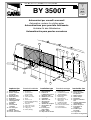
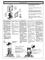
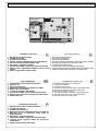
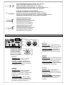
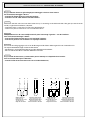
1 - Getriebemotor
2 - Schalttafel im Antrieb
3 - Funkempfänger
4 - Endschalterwinkel
5 - Zahnstange
6 - Außenantenne
7 - Blinkleuchte “Tor in
Bewegung”
8 - Schlüsselschalter
9 - IR Lichtschranke
10 -Lichtschrankeensäule
11- Toranschlag
12- Sicherheitsleiste
1 - Gearmotor
2 - Control panel
(incorporated)
3 - Radio receiver
4 - Limit-switch tabs
5 - Rack
6 - Electric lock
7 - Flashing light indicating
door movement
8 - Antenna
9 - Safety photocells
10 -Photocell column
11- Wing stop
12- Safety ribbing
Impianto tipo
Installation type
Standard montage
Instalación tipo
1 - Motorreductor
2 - Cuadro de mando
incorporado
3 - Radiorreceptor
4 - Aletas de tope
5 - Cremallera
6 - Selector mediantel
lave
7 - Lámpara intermitente
de movimiento
8 - Antena receptora
9 - Fotocélulas de
seguridad
10 - Columna para
fotocélula
11- Tope puerta
12- Protector de seguridad
1 - Motoréducteur
2 - Armoire de
commande incorporé
3 - Récepteur radio
4 - Buttées fin de corse
5 - Crémaillère
6 - Sélecteur a clé
7 - Clignotant de
mouvement
8 - Antenne de réception
9 - Photocellules de
sécurité
10 - Colonne pour
photocellule
11- Butée d'arrêt
12- Dispositif de securité
Standard installation
1 - Motoriduttore
2 - Quadro comando
incorporato
3 - Ricevitore radio
4 - Alette finecorsa
5 - Cremagliera
6 - Selettore a chiave
7 - Lampeggiatore di
movimento
8 - Antenna
9 - Fotocellule di
sicurezza
10 - Colonnina per
fotocellula
11- Battuta d'arresto
12- Costola di sicurezza
Automazioni per cancelli scorrevoli
Automation systems for sliding gates
Automatisations pour pourtails coulissants
Antriebe für den Schiebetore
Automatización para puertas correderas
2 x 1
2 x 1.5
RG58
4
7
5
3
1
2
4
9
10
2 x 1 - TX
4 x 1 - RX
4 x 2.5 / 220 - 380V
2 x 1 - TX
9
6
10
11
8
4 x 1 - RX
12
9

2
Optional:
CGZ6 30x30 module 6
rack in galvanised sheet
steel.
Zubehor:
CGZ6 verzinkte Zahn-
stange 30 x 30, Modul 6
aus Walzstahl.
Attenzione! Controllate che le apparecchiature di comando, di sicurezza e gli accessori siano originali CAME; ciò garantisce e rende l'impianto
di facile installazione e manutenzione.
Important: for easy installation and maintenance, we recommend using original CAME control systems, safety systems and accessories.
Attention: contrôler que les apareillages de commande, de sécurité et les accessoires, sont originaux CAME; cela permet et garantit une pose
et un entretien aisés de l'installation.
Achtung: es empfiehlt sich, original CAME-Steuergeräte und Sicherheitsvorrichtungen mit den entsprechenden Zubehör zu montieren, um eine
einwandfreie und problemlose Montage und Wartung der Anlage zu gewährleisten.
Atencion: comprobar que los equipos de mando, de seguridad y los acesorios sean originales CAME, lo cual garantiza y facilida el uso y el
mantenimiento del aparato.
Accessoires :
Crémaillère galvanisée
CGZ6 30 x 30 module 6
en acier laminé.
Accesorios :
CGZ6 Cremallera cin-
cada 30 x 30 módulo 6
de acero laminado.
Accessori:
CGZ6 Cremagliera zin-
cata 30x30 modulo 6 in
acciaio laminato.
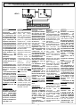
- Motoriduttore idoneo
alla movimentazione di
cancelli scorrevoli fino
ad un peso max. di 3500
kg.
- Progettato e costruito
interamente dalla
CAME, risponde alle vi-
genti norme di sicurez-
za (UNI 8612), con gra-
do di protezione IP54.
- Garantito 12 mesi sal-
vo manomissioni.
- Gear motor designed for
powering sliding gates
weighing up to 3500 Kg.
- Designed and
constructed entirely by
CAME; conforms to (UNI
8612) safety standards
with IP 54 protection
rating.
- 12 mounth guarantee;
guarantee void if unit is
tampered with.
- Motoréducteur adapt
au déplacement de
portail coulissants
ayant un poids maxi-
mum de 3500 Kg.
- Il a été entièrement
conçu et costruit par les
Ets CAME, confor-
méement aux normes
de sécurité en viguer
(UNI 8612) avec degré
de protection IP54.
- Il est garanti 12 mois
sauf en cas d'altértions.
- Getriebemotor für den
Antrieb von Schiebetoren
mit einem Höchstgewicht
von 3500 kg.
- Vollständig von der
CAME geplant und herge-
stellt, entsprechend den
geltenden Sicherheits-
bedigungen (UNI 8612)
mit Schutzgrad IP54.
- 12 Monate Garantie,
Bedienungs - und Monta-
ge-fehler ausgeschlos-
sen.
- Motorreductor ade-
cuado para la movi-
mentación de puertas
correderas de hasta
3500 Kg máximo de
peso.
- Diseñado y construido
totalmente por CAME,
con arreglo a las
vigentes normas de
seguridad (UNI 8612)
con grado de protección
IP54.
- Garantia de 12 meses
salvo manipulaciones.
Modéles:
BY 3500T motoréducteur
irréversible triphasé 750
W.
Modelle:
BY 3500
selbsthemmender
Drehstrom-
Getriebemotor.
Modelos:
BY 3500 motorreductor
irreversible trifase.
Model:
BY 3500T non-reversible,
triple-phase gear motor.
Modello:
BY 3500T motoriduttore
irreversibile trifase 750 W.
Dati relativi ai valori di alimentazione nominale e a condizioni di apertura standard
Data refers to nominal power supply and standard conditions of aperture
Données relatives aux valeurs d'alimentation nominale et à des conditions d'ouverture standard
Daten der Stromversorgungsnennwerte und Standardöffnungsbedingungen
Datos relativos a los valores de la tensión nominal y a las condiciones de apertura estándar
DESCRIZIONE TECNICHE -
TECHNICAL DESCRIPTION
- DESCRIPTION TECNIQUE -
TECNISCHE BESCHREIBUNG
DESCRIPCIÓN TÉCNICA
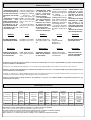
CARATTERISTICHE TECNICHE -
TECHNICAL SPECIFICATIONS
- CARACTERISTIQUES TECNIQUES -
TECNISCHE DATEN
CARACTERISTICAS TECNICAS
MOTORIDUTTORE VERSIONE
GRADO DI
PROTEZIONE
PESO ALIMENTAZIONE
CORRENTE
NOMINALE
POTENZA
INTERMITTENZA
LAVORO
RAPPORTO DI
RIDUZIONE
SPINTA
VELOCITÁ DI
TRASLAZIONE
GEARMOTOR VERSION
PROTECTION
RATING
WEIGHT POWER SUPPLY
NOMINAL
CURRENT
POWER DUTY CICLE
REDUCTION
RATIO
PUSH LINEAR SPEED
MOTORÉDUCTEUR VERSION
DEGRÉ DE
PROTECTION
POIDS ALIMENTATION
COURANT
NOMINAL
PUISSANCE
INTERMITTENCE
DE TRAVAIL
RAPPORT DE
REDUCTION
POUSSÉE
VITESSE DE
TRASLATION
GETRIEBEMOTOR VERSION SCHUTZGRAD GEWICHT
STROM_
VERSORGUNG
NENNSTROM LEISTUNG EINSCHALTDAUER
UNTERSETZUNGS_
VERHÄLT N I S
REGELBARER
ÜBERTRAGUNGS-
GASCHWINDIGKEIT
MOTORREDUCTOR VERSION
GRADO DE
PROTECCION
PESO ALIMENTACION
CORRIENTE
NOMINAL
POTENCIA
INTERMITENCIA
TRABAJO
RELACION DE
REDUCCION
EMPUJE
TIEMPO DE
CARRERA
BY3500 T 2.0 IP 54 74 Kg 220/380V a.c. 2 A 750 W 50 % 1/28 3500 N 10,5 m/min

3
- La hoja de la puerta
debe estar suficien-
temiente rigida y
compacta
- Las ruedas de
deslizamiento deben
estar perfecta y
engrasadas adecua-
damente.
- La guia de desl-
izamiento debe estar
bien fijada en el sue-
lo, sobresaliendo a lo
largo de su entera
longitud, sin huecos
ni irregularidades
(que podrian obsta-
culizar el movimiento
de la puerta).
- La guia superior debe
tener el justo juego
con la puerta metá-
lica (para garantizar
un movimiento regu-
lar y silencioso).
- Disponer un tope para
apertura y el cierre.
- Disponer un conducto
para los cables eléc-
tricos que cumpla
con las disposiciones
de mando y segu-
ridad.
- Die Leistungfähigkeit
der feststehenden und
beweglichen Teile des
Tores überprüfen.
- Das Tor sollte aus-
reichend stabil sein.
- Die Gleitrollen sollten in
guten Zustand und
angemessen gesch-
miert sein.
- Die Gleitführung auf
dem Boden sollte sich in
optimaler Position be-
finden: gut auf dem Bo-
den befestigt, in seiner
Gesamtlänge vollstän-
dig über dem Boden,
ohne Vertiefungen und/
oder Unebenheiten, die
die Torbewegung behin-
dern können.
- Die oberen Führungs-
schienen sollten das
richtige Spiel zum Tor
haben, um ein präzises
und regelmäßiges
Gleiten zu garantieren.
Einen Anschlag für Tor
Auf und Tor Tu sollte
vorhanden sein.
- Den Lauf der elektri-
schen Kabel nach den
Steuerungs- und Sicher-
heitsbestimmungen
vorsehen.
- Le panneau mobile du
portail devra être
suffisamment rigide et
solide.
- Les roues de
coulissement devront
être en très bon état.
En outre, elles devront
être convenablement
graissées.
- Le rail de guidage
devra être bien fixée
au sol. De plus, il
devra se présenter
entièrement en sur-
face sans affaisse-
ments ou irrégularités
(qui pourraient empê-
cher le mouvement du
portail).
- Le guide supérieur
devra avoir un jeu
convenable avec le
portail (pour permet-
tre un mouvement
régulier et silencieux).
- Prévoir une butée
d’arrêt à l’ouverture et
à la fermeture.
- Prévoir le passage des
câbles électriques
selon les dispositions
de commande et de
sécurité.
- The gate must be
sufficiently rigid and
solid.
- The wheels on which the
gate slide must be in
perfect condition and
adequately lubricated.
- The wheel guide must
be firmly attached to the
ground, completely
exposed, and without
any dips or irregular
sections which might
hinder the movement of
the gate.
- The upper guide must
allow for the correct
amount of play in order
to guarantee smooth
and silent movement of
the gate.
- Aperture and closure
stops must be installed.
- The wiring must be
routed as specified by
the control and safety
requirements.
- Controllare che l'anta
sia rigida e compatta.
- Controllare che le
ruote di scorrimento
siano in buono stato e
adeguatamente in-
grassate.
- La guida a terra dovrà
essere ben fissata al
suolo, completamen-
te in superficie in tutta
la sua lunghezza,
priva di affossamenti
e/o irregolarità che
possano ostacolare il
movimento del can-
cello.
- I pattini-guida supe-
riori non devono
creare attriti.
- Prevedere una battuta
d'arresto in apertura e
una in chiusura.
- Prevedere il percorso
dei cavi elettrici come
da impianto tipo.
PRECAUZIONI -
BEFORE INSTALLING .....
- AVANT D'INSTALLER L'AUTOMATISME ..... -
VOR DEN INSTALLATION ÜBERPRÜFEN
ANTES DE INSTALAR EL AUTOMATISMO
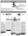
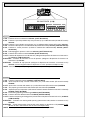
MISURE D'INGOMBRO -
OVERALL DIMENSIONS
- MEASURES D'ENCOMBRENT -
ABMESSUNGEN
- MEDIDAS
275
295
480
167
171
222
578

4
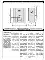
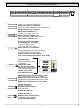
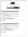
Predisporre, dimen-
sionandola in base alle
misure dell'automa-
zione, una piazzola in
cemento con annegate
le zanche di ancoraggio
(alla misura indicata)
che permetteranno il
fissaggio del gruppo. La
base di fissaggio dovra'
risultare perfettamente
in bolla, pulita in tutte le
sue estremita', con il
filetto delle viti
completamente in
superfice.
N.B.: Dalla stessa
dovranno emergere i
tubi flessibili per il
passaggio dei cavi di
collegamento elettrico.
- Unire la controbase e
le due zanche con le viti
e i dadi in dotazione.
Prepare a concrete base
of dimension suitable for
the size of the actuating
system.
The anchor bolts should
be embedded in the
concrete in the positions
indicated; the drive unit
is then attached to this
bots. The anchor plate
must be perfectly level and
absolutly clean; the bolts
threads must be completly
exposed.
N.B.: The flexible tubes
for the electrical wiring
must be embedded in the
base and protude in the
correct position.
- Using the hardware
supplied with the unit, join
the base to the two
clamps.
Préparer une plate-for-
me en ciment dans
laquelle sera noyées les
pattes d’encrage (à la
mesure indique) qui
permettront la fixation
du groupe. Les
mesures de la
plateforme seront
basées sur les mesures
de l’automation.
La base de fixation
devrà être parfaitement
de niveau et propre sur
toute sa surface et le
filet des vis devra être
complètement en
surface.
N.B. Les câbles pour le
branchement électrique
devront sortir de cette
base.
- Relier la contrebase et
les deux agrafes à l'aide
de la boullonerie
fournie.
Eine Zementfläche nach
den Einbaumaßen
vorbereiten. Die
Bodenanker It. Maßen
der Grundplatte in die
Zementfläche einsetzen.
Die Befestigungsunter-
lage muß in seiner
gesamten Länge
vollkommen eben und
sauber sein. Das
Gewinde der Schrauben
müssen gänzlich.
hervorstehen und die
Kabel für den Elektro-
anschluß müssen
herausrgen.
Wichtig: Es ist
empfehlenswert, daß die
Zementfläche etwa 50
mm über den Boden
herausragt, um zu
vermeiden, daß Wasser-
ansammlungen die
Anlage beschädigen
können.
- Die Ankerplatte mit den
mitgelieferten Schrau-
ben an den beidenì Fun-
damentarken festschra-
uben.
Predisponer, en función
de las medidas del au-
tomatismo, una plata-
forma de cemento
sumergiendo los sopor-
tes de anclaje (según la
medida indicada) que
consienten fijar en
conjunto. La base de
fijación debe estar
perfectamente nive-
lada, limpia en todos
sus extremos, con la
rosca de los tornillos
totalmente in superfi-
cie.
N.B. De ésta deben
sobresilar los tubos
flexibles para el paso de
los cables para las
conexiones eléctricas.
- Unir la controbase y
los estribos con los
pernos suministrados.
FISSAGGIO BASE MOTORE -
MOTOR TO BASE ANCHORAGE
- FIXATION DE LA PLAQUE DU MOTEUR
BEFESTIGUNGS DER MOTORBASIS
- FIJACIÓN BASE MOTOR
142 mm.
220 mm.
Struttura fissa
Wall
Structrure fixe
Feste Struktur
Estructura fija
Anta cancello
Gate wing
Panneau mobile du portail
Gleitachse
Puerta
Zanche
Anchor stays
Agrafes
Verankerung
Barras de hierro de fijación
Piastra di fissaggio
Fixing plate
Plaque de fixation
Gleitachse
Placa de fijación
Piazzola in cemento
Concrete base
Plate-forme en ciment
Plattenachse
Plataforma de cemento
Cavi
Cable
Câbles
Kabel
Cables
Cremagliera
Rack-limit
Cremaillére
Zahnstange
Cremallera
50 mm.

5
PortaPorta
PortaPorta
Porta
Door
PortePorte
PortePorte
Porte
Tür
PuertaPuerta
PuertaPuerta
Puerta
Chiave
Key
Clé
Schlüssel
Llave
Bulloni
Bolts
Boulons
Mutterschrauben
Pernos
- Inserire la chiave e girarla in senso
orario, togliere la porta, i quattro
bulloni e l'armadio.
- Insert the key and turn it clockwise, remove
the door, remove the four bolts and remove
the housing.
- Introduire la clé et la tourner dans le sens
des aiguilles d'une montre, enlever la
porte, les quatre boulons puis l'armoire.
- Den schlüssel einfügen und im Uhrzeigersinn
drehen, die Tür, die vier Mutterschrauben und
den Schrank entfernen.
- Introducir la llve y girarla en sentido
horario, quitar la puerta, los quatro pernos
y el armario.
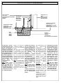
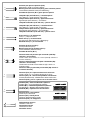
Nella fase preliminare di
posa, i piedini dovranno
sporgere di 5-10 mm. per
permettere allineamenti,
fissaggio della crema-
gliera e regolazioni
successive.
L'accoppiamento esatto
con la linea di scorrimen-
to del cancello è otteni-
bile dal sistema di rego-
lazione integrale (bre-
vettato) composto da:
- le asole che permet-
tono la regolazione
orizzontale;
- i piedini filettati in
acciaio che permet-
tono la regolazione
verticale e la messa in
bolla;
- le piastrine e i dadi di
fissaggio che rendono
solidale l'aggancio del
gruppo alla base.
During the initial phase of
installation, the feet should
protude by 5-10 mm. in
order to allow for
alignment, anchorage of
the rack and further
adjustments.
Perfect alignment with the
guide rail is made possible
by the (patented) built-in
regulation system, wich
consists of:
- slots for horizontal
adjustment;
- threaded steel feet for
vertical adjustment and
levelling;
- plates and bolts for
anchorage to the base.
Procéder maintenant à
la pose du groupe.
Dans la phase de pose
préliminaire, les broches
devront dépasser de 5 à
10 mm afin de permettre
les alignements et les
réglages nécessaires
après la pose.
L’accouplement exact
avec la ligne de coulis-
sement du portail s’ef-
fectue par le système de
réglage hauteur (breve-
té) dont le groupe est
pourvu, et qui comprend
plus précisément:
- les trous oblong
permettant le réglage
horizontal;
- les broches filetées en
acier qui donnent le
réglage vertical et la
mise à niveau;
- les plaques et les
écrous de fixation qui
assemblent solide-
ment le groupe à la
plaque de fixation
scellée.
Nun die Montage des
Antriebsmotors vorne-
hmen. Die genaue Kop-
plung mit der Gleitlinie
des Tors wird von dem
integrierten Einstel-
lungssystem (patentiert)
garantiert, mit dem das
Aggregat ausgestattet ist
und zwar:
- die Osen für die
horizontale Einstellung,
- die Gewindefüße aus
Stahl für die vertikale
Einstellung und die
Nivellierung,
- die Befestigungsplät-
tchen und -muttern zur
soliden Befestigung des
Aggregats an die
Bodenplatte.
- Während der Vorberei-
tungsarbeiten der
Montage sollten die
Füße 5-10 mm
herausragen, um
Ausfluchtungen und
Einstellung auch nach
der Fertigstellung zu
ermöglich.
En la fase previa del
emplazamiento, los
pies deben sobresalir 5-
10 mm para consentir la
alineación, la fijación de
la cremallera y las
regulaciones suce-
sivas.
El acoplamiento exacto
con la linea de
deslizamiento de la
puerta metálica se
obtiene mediante el si-
stema de regulación
integral (patentado) que
consta de:
- los agujeros ovalados
que consienten la
regulación horizontal;
- los pies roscados de
acero que permiten la
regulación vertical y la
nivelación;
- las placas y las
tuercas de fijación que
hacen solidario el
enganche del
conjunto con la base.
Armadio
Housing
Armoire
Schrank
Armario
Piastra di fissaggio
Fixing plate
Plaque de fixation
Gleitachse
Placa de fijación
Asole
Slots
Fentes
Schilitzlöcher
Ojetes
Accoppiamento pignone-cremagliera
con gioco 1÷2 mm.
Rack-to-pinion coupling with 1÷2 mm. clearanc
e
Assemblage pignon-crémaillère avec jeu
de 1 à 2 mm.
Zwischen Zahnstange und dem Antriebsritzel
1÷2 mm. Spiel einstellen
Acoplamiento piñon-cremaliera
1÷2 mm. de juego
Regolazione orizzontale e fissaggio
Horizontal adjustment unit and achorage
Réglage horizontal et fixation
Horizontale Einstellung
Regulación horizontal y fijación
Regolazione verticale - messa in bolla
Vertical adjustment and unit leveling
Réglage vertical - mise à niveau
Vertikale Einstellung
Regulación vertical y nivelación
5 ÷ 10 mm
Ingresso cavi
Cable entrances
Passage des câbles
Kabeleinfuhrüngen
Entrada cables
1÷2 mm.
POSA DEL GRUPPO -
UNIT INSTALLATION -
INSTALALTION DU GROUPE -
AUFSTELLUNG DES AGGREGATS
COLOCACIÓN DEL GRUPO

6
1) Colocar el motor-
reductor en la posición
para el desbloqueo.
2) Fijar la cremallera en
la puerta metálica como
se indica a continua-
ción (fig. A).
- Apoyar la cremallera
en el piñón motorre-
ductor y deslizar ma-
nualmente la puerta
metálica fijando la
cremallera a lo largo de
su entera longitud.
- Finalizadas las opera-
ciones para la fijacion
de la cremallera, regular
los pies (por medio de
un destornillador) de
modo que se obtenga el
justo juego entre el
piñón y la cremallera (1-
2 mm).
N.B. Esto hace que el
peso de la puerta
metálica no cargue
bobre el conjunto.
Die Zahnstange auf dem
Getrieberitzel anlehnen
(nachdem dieser in die
Eintriegelungsposition
gebracht wurde), manuell
das Tor gleiten lassen
und die Zahnstange in
seiner gesamten Länge
befestigen (Abb. A).
Darauf achten, daß bei
Metallzahnstangen im
Meterraster die einzelnen
Stücke nicht auf Stoß
montiert werden,
sondern auf Fortlauf der
Zahnung (Zahnstange
am Stroß unten anlegen
zur Überprüfung).
Die verstellbaren Füße
des Antriebsmotors (mit
einem Schraubenzieher)
so einstellen, daß
zwischen Ritzel und
Zahnstange ein Spiel (1-
2 mm) besteht. Dadurch
wird vermieden, daß das
Gewicht des Tores auf
dem Aggregat lastet.
1) Débloquer le moto-
réducteur;
2) Procéder à la fixation
de la crémaillère sur le
portail de la façon
suivante (fig. A).
Placer la crémaillère
sur le pignon motoré-
ducteur et faire coulis-
ser le portail manuel-
lement en fixant la
crémaillère sur toute sa
longueur.
Lorsque la fixation de la
crémaillère est termi-
née régler les broches
(en utilisant un tour-
nevis) de façon à
obtenir un jeu conve-
nable (1-2 mm) dans
l’assemblage du
pignon et de la
crémaillère.
N.B. Ceci pour éviter
que le poids du portail
ne repose sur le
groupe.
1) Release the gearmotor;
2) Attach the rack to the
gate as described below:
- position the rack on the
pinion of the gearmotor
and slide the gate
manually in order to attach
the rack along its entire
lenght (see fig. A);
- when the rack is
attached to the gate,
adjust the feet using a
screwdriver until the play
between the pinion and
the rack is correct (1-2
mm.).
N.B. : This play ensures
that the weight of the gate
does not rest on the until.
1) Sbloccare il moto-
riduttore;
2) Fissare la
cremagliera sul
cancello come segue:
- appoggiare la crema-
gliera sul pignone del
motoriduttore e far
scorrere manualmente
il cancello fissando la
cremagliera in tutta la
sua lunghezza (fig. A);
- ultimata l'operazione
di fissaggio della
cremagliera, regolare i
piedini (servendosi di
un cacciavite) in modo
da ottenere il giusto
giuoco tra pignone e
cremagliera (1-2 mm.).
N.B. : Questo evitera'
che il peso del cancello
vada a gravare sul
gruppo.
N.B: l'operazione di sblocco va effettuata a motore fermo.
N.B: perform this step with the motor stopped.
N.B: cette operation doit être effectuée lorsque le moteur est arrêté.
Anmerkung: der Entriegelungsvorgang muß bei ausgeschaltetem Motor
ausgeführt werden.
N.B: esta operación se debe efectuar con el motor parado.
Fig. A
Fig. B
Finecorsa
Switch tabs
Fins de cours
Endschalterbügel
Aletas de tope
Cremagliera
Rack-limit
Cremaillere
Zahnstange
Cremallera
Sblocco (svitare completamente)
Release (fully unscrew)
Entriegelt (ganz ausschrauben)
Déblocage (dévisser complétement)
Desbloqueo (desenroscar completamente)
Engage (fully screw)
Blocco (avvitare completamente)
Blockierend (ganz einschrauben)
Blocage (visser complétement)
Bloqueo (enroscar completamente)
FISSAGGIO CREMAGLIERA-
ATTACHING THE RACK/LIMIT
- FIXATION CREMAILLERE -
MONTAGE DE ZAHNSTANGE
FIJACIÓN DE LA CREMALLERA
SBLOCCO MOTORIDUTTORE -
GEAR RELEASE
- OPÉRATION DE DÉBLOCAGE -
ANTRIEBSENTRIEGELUNG
DESBLOQUEO MOTORREDUCTO

7
Se la cremagliera é gia'
fissata, procedere diret-
tamente alla regola-
zione dell'accoppia-
mento pignone-crema-
gliera.
Eseguite tutte le
regolazioni, fissare il
gruppo stringendo i
dadi di fissaggio.
If the rack is already
attached, proceed directly
to the adjustment of the
rack/pinion coupling.
When the necessary
adjustment have been
completed, fasten the unit
in position by tightening
the two anchor bolts.
Si la crémaillère est
déjà fixée, utiliser le
système de réglage
hauteur pour assem-
bler correctement le
pignon et la crémaillère.
Exécuter tous les
réglages, fixer le groupe
en serrant les deux
écrous de fixation.
Nach diesen Einstel-
lungsarbeiten das
Aggregat durch Anziehen
der beiden Muttem
befestigen.
Si la cremallera ya ha
sido fijada, hay que
regular el acoplamiento
piñón-cremallera. Una
vez realizados los
ajuste, fijar el conjunto
cerrando las dos
tuercas de fijación.
- Posizionare sulla
cremagliera le alette
finecorsa che deter-
mineranno con la loro
posizione, la misura
della corsa (fig.B-pag 6).
Nota: evitare che il
cancello vada in battuta
contro il fermo mec-
canico, sia in apertura
che in chiusura.
- Position the limit-switch
tabs (whose positions
determine the limits of
gate travel - see fig. B-
page 6) on the rack.
Note: do not allow the gate
to strike the mechanical
stops in the open or
closed positions.
- Positionner les ailettes
de fin de course sur la
crémaillère.
Leur position déter-
minera la mesure de la
course (fig. B-p. 6).
Remarque: il faut éviter
que le portail se porte
en butée contre l'arrêt
mécanique, aussi bien
en ouverture qu'en
fermeture.
- Die Endschalter-Rippen,
die durch ihre Stellung
den Torlauf festlegen
(Abb. B-S.6), auf der
Zahnstange positionie-
ren.
Hinweis: das Tor sollte
weder beim Öffnen noch
beim Schließen auf den
mechanischen Endan-
schlag auftreffen.
- Colocar en la
cremallera las aletas de
final de carrera que
determinan, con su
posición, la medida de
la carrera (fig. B-pág 6).
Nota: evitar que la
puerta choque contro el
tope mecánico, tanto en
la apertura como en el
cierre.
Fig. C
Fig. D
- The motor is designed to
operate with 380V a.c., triple
phase power, remove the
control panel, bracket and
cover.
Now, make all the electrical
connections as shown on
the figure C, replace all
disassembled components
in their original positions and
Short-circuit contacts 220-
COM on the control panel
as shown on fig. D.
- Le moteur est prévu pour
une alimentation à 380V a.c.
triphasée.
En cas d'alimentation à 220V
triphasée, enlever l'armoire
de commande, l'étrier, le
couvercle et exécuter les
branchements de la façon
indiquée (C). Une fois cette
opération terminée,
procéder au remontage et
court-circuiter, sur l'ar-
moire de commande, les
contacts 220-COM com-
me indiqueé sur la fig. D
- Der Motor ist für eine
Versorgung mit 380-V
Drehstrom vorbereitet.
Bei einer Versorgung mit
220-V Drehstrom das
Steuergerät, den Bügel und
den Deckel entfernen
ausführen (Abb. C). Dann
alle Teile neuerlich
montieren und die auf dem
Steuergerät befindlicken
Kontakte 220-COM der
Abb. D entsprechend Kurz-
schließen.
- El motor está
predispuesto para ser
alimentado a 380 V trifase.
En el caso de ali-
mentación a 220 V trifase,
extraer el quadro de
mando, el estribo, la tapa
y realizar las conexiones
como rapresentado (fig.
C). Una vez terminado,
volver a colocarlo todo y
cortocircuitar en el
quadro de mando los
contactos 220-COM como
indicado en la fig. D.
C
O
M
2
2
0
3
8
0
B
L
U
B
I
A
N
C
O
R
O
S
S
O
W
V
U
TSR
- Il motore è predisposto
per essere alimentato a
380V trifase. In caso di
alimentazione a 220V
trifase, togliere il quadro
comando, la staffa, il
coperchio ed eseguire i
collegamenti come da fig.
C. Alla fine riposizionare
il tutto e cortocircuitare
sul quadro i contatti 220-
COM come da Fig. D.
FISSAGGIO FINECORSA -
ATTACHING THE SWITCH TABS
- FIXATION BUTTÉES FINS DE COURS
MONTAGE DE ENDSCHALTERBÜGEL -
FIJACIÓN DE LA ALETAS DE TOPE
ALIMENTAZIONE A 220 V -
220 V POWER INPUT
- ALIMENTATION À 220 V -
VERSORGUNG MIT 220 V
ALIMENTACIÓN A 220 V
W
2
W
1
U
1
U
2
V
2
V
1
W
2
U
2
V
2
W
1
U
1
V
1
Alimentazione 380V
Alimentazione 220V
Quadro comando
Control panel
Armoire de commande
Schalttafel
Cuadro de mando
Staffa
Staffa
Staffa
Staffa
Staffa
Coperchio
Coperchio
Coperchio
Coperchio
Coperchio

9
-
Courtesy Light.
A light that illuminates
the manoeuvring zone; after an open-
ing command, the light remains on for
a fixed time of 5 minutes and 30 sec-
onds (E-EX), see page 15;
-"
Operator present" function:
Gate
operates only when the pushbutton is
held down (the radio remote control
system is deactivated);
-
Pre-flashing
for 5 seconds, while the
door is opening and closing;
-
Master function
; the panel assumes
all the command functions when two
paired motors are used (see page 24);
-
Slave function
; this panel is exclu-
sively controlled by the “MASTER” (see
page 24);
-
Enabling
functions of partial stop or
re-closure during opening, normally-
closed contact (2-CX), select one of the
two functions by setting dip (see
selection of functions);
-
Type of command:
-open-close-reverse by button and
transmitter;
-open-stop-close-stop by button and
transmitter;
-open only by transmitter.
Adjustments
- Automatic closure time;
- Partial opening time.
The power supply to the circuit should
be connected to terminals R, S and T,
and is protected by a 8A fuse on the
main power line. The ZT4 control panel
is factory set for 380V power supply. If
the power supply is 220V, it is
necessary to move the jumper which
short-circuit terminals «380» and
«COM» so that it short-circuits
terminals «220» and «COM» (see
pag.7). The Control systems are
powered by low voltage and protected
with a 2A fuse. The total power
consumption of 24 V accessories must
not exceed 20W.
Fixed operating time of 150 seconds.
Safety
Photocells can be connected to obtain:
-
Re-opening
during the closing cycle
(2-C1);
-
Re-closing
during the opening cycle
(2-CX, see dip 8-9);
-
Partial stop
, shutdown of moving gate,
with activation of an automatic closing
cycle (2-CX, see dip 8-9);
-
Total stop
(1-2), shutdown of gate
movement without automatic closing; a
pushbutton or radio remote control
must be actuated to resume movement;
N.B
: If an NC safety contact (2-C1, 2-
CX, 1-2) is opened, the LED will flash to
indicate this fact;
safety devices (for example, the
photocells);
-
Obstacle presence detection.
When
the motor is stopped (gate is closed,
open or half-open after an emercency
stop command), the transmitter and the
control pushbutton will be deactivated
if an obstacle is detected by one of the
safety devices (for example, the
photocells);
-
Safety test function.
The control unit
will now check the safety system every
time an opening or closing command
is given (see pag.14).
Accessories which can be
connected
-Cycle lamp or courtesy light (60 Watt,
see pag.15);
Other functions
-
Automatic closing:
The automatic
closing timer is automatically activated
at the end of the opening cycle. The
preset, adjustable automatic closing
time is automatically interrupted by the
activation of any safety system, and is
deactivated after a STOP command or
in case of power failure;
-
Partial opening.
Opening of the gate
to allow for foot traffic; activated by
connecting to terminals 2-3P and
adjusted with the AP-PARZ. trimmer.
With this function, the automatic closing
can vary in the following way:
1) Dip 12 set to ON: after a partial open-
ing, the time for automatic closing func-
tions independently of the adjustment
of the TCA trimmer and of the position
of Dip 1; it is set at 8 seconds.
2) Dip 12 set to OFF: after a partial
opening, the time for automatic clos-
ing is adjustable only if Dip 1 is set to
ON.
-
Cycle lamp.
The lamp which lights the
manoeuvring zone: it remains lit from
the moment the doors begin to open
until they are completely closed
(including the time required for the
automatic closure). In case automatic
closure is not enabled, the lamp
remains lit only during movement (E-
EX), see p.15;
DESCRIPTION ZT4 CONTROL PANEL
ENGLISH
Important! Disconnect the unit
from the main power lines before
carrying out any operation inside the
unit.

13
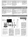
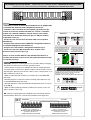
SCHEDA BASE -
MOTHERBOARD
- CARTE BASE -
GRUNDPLATINE
- TARJETA BASE
CH1
T.C.A.
AP.PARZ.
AF
ZT4
2
1
34
5
67
8910
ON
1211 13 14 15 16 17 18 19 20
ON
CH2
FUS.LINEA 5A
FUSIBILE
ACCESSORI 2A
DIS. 25215
7
4
8
6
3
9
5
1
2
MAIN COMPONENTS
1 Terminal block for external connections
2 8A line fuse
3 2A accessories fuse
4 Socket AF radiofrequency board (see table)
5 Radio-code save buttons
6 "Function selection" Dip-switch
7 Trimmer AP.PARZ.: Partial opening adjustment
8 Trimmer TCA: automatic closing time adjustment
9 Radio-code LED
GB
HAUPTKOMPONENTEN
1 Anschluss-Klemmenleiste
2 8A-Sicherung Leitungs
3 2A-Sicherung Zubehörs
4 Steckanschluß Funkfrequenze-Platine AF (sehen Tabelle)
5Knöpfe zum Abspeichern der Radiocodes
6 "Funktionswahl" Dip-switch
7 Trimmer AP.PARZ.: Einstellung Teilöffnung
8 Trimmer TCA: Einstellung Zeiteinstellung Schließautomatik
9 LED Kontrolleuchte zur Anzeige von Radiocode
D
COMPONENTES PRINCIPALES
1 Caja de bornes para las conexiónes
2 Fusibles de línea 8A
3 Fusible accesorios 2A
4 Conexión tarjeta radiofrecuencia AF (vedas tabla)
5 Botones de memorización del código radio
6 Dip-switch "seleción función"
7 Trimmer AP.PARZ.: regulación apertura parcial
8 Trimmer TCA: regulación cierre automático
9 Indicador luminoso código radio
E
COMPOSANTS PRINCIPAUX
1 Plaque à bornes pour les branchements
2 Fusibles de ligne 8A
3 Fusible accessoires 2A
4 Branchement carte radiofréquence AF (voir tableau)
5 Boutons mise en mémoire code radio et
programmation
6 Dip-switch "sélection fonction"
7 Trimmer AP.PARZ.: réglage ouverture partielle
8 Trimmer TCA: réglage temps de fermeture
automatique
9 LED de segnalisation code radio
F
COMPONENTI PRINCIPALI
1 Morsettiere di collegamento
2 Fusibili di linea 8A
3 Fusibile accessori 2A
4 Innesto scheda radiofrequenza AF (vedi tabella)
5 Pulsanti memorizzazione codice radio
6 Dip-switch "selezione funzioni"
7 Trimmer AP.PARZ.: regolazione apertura parziale
8 Trimmer TCA: regolazione tempo di chiusura auto-
matica
9 LED di segnalazione codice radio
I

14
TEST FUNZIONAMENTO FOTOCELLULE -
PHOTOCELL FUNCTION TEST
- TEST FONCTIONNEMENT PHOTOCELLULES
TEST FÜR FUNKTIONIEREN DER LICHTSCHRANKEN
- TEST FUNCIONAMIENTO FOTOCELULAS
«DOC»
E4 10 11 TS 1 2 3 3P 4 5 6 7 2MOT
N.O.
N.C.
C.
+
-
+
-
Consente alla
centralina di verifica-
re l'efficenza dei
dispositivi di sicurez-
za (fotocellule) dopo
ogni comando di
apertura o di chiusu-
ra. Un eventuale ano-
malia delle fotocellule
viene identificata con
un lampeggio del led
sul quadro comando,
di conseguenza an-
nulla qualsiasi fun-
zione del
radiocomando e del
pulsante.
Collegamento elettri-
co per il funziona-
mento del test di si-
curezza:
I trasmettitori e i rice-
vitori delle fotocellule
devono essere colle-
gati nel seguente
modo:
- il trasmettitore della
fotocellula collegato
sui morsetti TS-10,
mentre il ricevitore
collegato sui morsetti
10-11 (vedi disegno).
- selezionare il dip 13
in ON per attivare il
funzionamento del
test.
IMPORTANTE:
quando si esegue la
funzione test di sicu-
rezza, VERIFICARE
che NON CI SIANO
PONTI tra i contatti 2-
CX, 2-C1 e, se non uti-
lizzati, escluderli tra-
mite dip 7 e 8.
The control unit will now
check the safety
system (photocells)
every time an opening
or closing command is
given. If a photocell
malfunctions, a LED
will flash on the control
panel, and the radio
transmitter and the
control pushbutton will
be deactivated.
Electrical connections
required for safety test
function.
Photocell lamps and
sensors must be
connected as follows:
- connect the photocell
sensor across
terminals TS-10.
Connect the photocell
lamp across terminals
10-11 (see diagram);
- move dip switch 13 to
ON, which will activate
the test function.
IMPORTANT:
when the safety test is
enabled, CHECK that
THERE ARE NO
JUMPERS between
contacts 2-CX, 2-C1
and, if not being used,
exclude them using dip
switches 7 and 8.
ENGLISH
ITALIANO
Cela permet au boîtier
de vérifier le bon
fonctionnement des
dispositifs de sécurité
(photocellules) aprés
chaque commande
d'ouverture ou de
fermeture. Les
é ventuelles
anomalies des
photocellules sont
signalées par un
clignotement de la led
sur l'armoire de
commande, et la
conséquente annula-
tion de toute fonction
de l'émetteur et du
bouton-poussoir.
Branchement électri-
que pour le fonction-
nement du test de
sécurité.
Les émetteurs et les
récepteurs des
photocellules doivent
être branchés de la
manière suivante:
- l'émmetteur de la
photocellule sur le
bornes TS-10, celui du
récepteur sur les
bornes 10-11 (voir
dessin);
- mettre le dip-switch
13 sur ON pour activer
le fonctionnement du
test.
IMPORTANT:
quand on active la
fonction test de
sécurité, VERIFIER
qu'il N'Y A PAS DE
PONTS entre les
contacts 2-CX, 2-C1
et, s'ils ne sont pas
utilisés, les exclure à
l'aide des
interrupteurs à
positions multiples 7
et 8.
Permite a la central
comprobar la
eficiencia en los
dispositivos de
seguridad
(fotocé lulas)
después de cada co-
mando de apertura y
cierre. Una posible
anomalía de las
fotocélulas se indica
a través de una luz
parpadeante del LED
en el cuadro de man-
do y, por lo tanto, se
anula cualquier
función del
transmisor y de la
tecla.
Conexión eléctrica
para el
funcionamiento de
las pruebas de
seguridad.
Los transmisores y
los receptores de las
fotocélulas deben
estar conectados de
la siguiente manera:
- el transmisor de la
fotocélula conectado
a los bornes TS-10,
el receptor a los
bornes 10-11 (ver
dibujo);
- seleccionar el dip
13 en ON para activar
el funcionamiento de
la prueba.
IMPORTANTE:
al activarse la
función test de
seguridad,
CONTROLAR que
NO HAYA PUENTES
entre los contactos
2-CX, 2-C1 y, si no se
utilizan,
inhabilitarlos me-
diante los dip 7 y 8.
Dadurch besteht die
Möglichkeit, die
Leistungsfähigkeit der
Sicherheitsvorrichtungen
(Lichtschranken) nach
jeder Öffnungs- und
Schließsteuerung zu
überprüfen.
Bei eventuell auftre-
tenden Betriebsstörun-
gen der Lichtschran-
ken leuchtet die
entsprechende LED
auf dem Steuergerät
auf und jede
Funksender- und
Drucktaster-Funktion
wird automatisch
annulliert.
Elektrischer Anschluß
für die Sicherheitstest-
Funktion.
Die Sender und
Empfänger der Licht-
schranken folgender-
maßen anschließen:
- Lichtschrankensen-
der auf den Klemmen
TS-10, Empfänger auf
den Klemmen 10-11
(siehe Abbildung)
- Dip-Switch 13 zur
Aktivierung der
Sicherheitstest-Funk-
tion auf ON stellen.
ACHTUNG:
wenn die Funktion
Sicherheits-test
gestartet wird, muß
KONTROLLIERT
werden, daß es
zwischen den
Kontakten 2-CX und 2-
C1 KEINE BRÜCKEN
GIBT. Falls die
Kontakten nicht
verwendet werden,
müssen Sie mit Dip 7
und 8 ausgeschlossen
werden.
FRANÇAIS
DEUTSCH
ESPANOL

15
E
E1
E
EX
U
W
V
R
S
T
R S T U V W E E1 EX
E4 10 11 TS 1 2 3 3P 4 5 6 7 2MOT
FC FA F
2 C1 CX B1 B2
Alimentazione 220V (a.c.) trifase)
220V (a.c.) power input three-phase
Alimentation 220V (c.a.) triphasée
Stromversorgung 220V (Wechselstrom) dreiphaseing
Alimentación 220V (a.c.) trifásica
Motore trifase 220/380V (a.c.)
220/380V (a.c.) three-phase motor
Moteur triphasée 220/380V (c.a.)
Motor dreiphasen 220/380V (Wechselstrom)
Motor trifásico 220/380V (a.c.)
Uscita 230V (a.c.) in movimento
(es.lampeggiatore - max. 25W)
230V (a.c.) output in motion
(e.g. flashing light - max. 25W)
Sortie 230V (c.a.) en mouvement
(ex. branchement clignotant - max. 25W)
Ausgang 230V (Wechselstrom) in Bewegung
(z.B. Blinker-Anschluß - max. 25W)
Salida de 230V (a.c.) en movimento
(p.ej. conexión lámpara intermitente - max. 25W)
Lampada ciclo (230V)
o cortesia (230V)
(230V) cycle lamp or (230V)
courtesy light
Lampe cycle (230V)
ou lampe passage (230V)
Betriebszyklus-Anzeigeleuchte
oder Torbeleuchtung (230V)
Lámpara ciclo (230V)
o luz de cortesía (230V)
Alimentazione accessori 24V (a.c.) max. 20W
24V (a.c.)Powering accessories (max 20W)
Alimentation accessoires 24V (c.a.) max. 20W
Zubehörspeisung 24V (Wechselstrom) max. 20W
Alimentación accesoios 24V (a.c.) max. 20W
Pulsante stop (N.C.)
Pushbutton stop (N.C.)
Bouton-poussoir arrêt (N.F.)
Stop-Taste (N.C.)
Pulsador de stop (N.C.)
Pulsante apre (N.O.)
Pushbutton opens (N.O.)
Bouton-possoir ouverture (N.O.)
Taste Öffnen (Arbeitskontakt)
Pulsador de apertura (N.O.)
1211 13 14 15 16 17 18 19 20O
N
LAMPADA CORTESIA
COURTESY LIGHT
LAMPE PASSAGE
TORBELEUCHTUNG
LUZ DE CORTESIA
(
16 ON
-
17 OFF
)
V W E E1 EX
LAMPADA CICLO
CYCLE LAMP
LAMPE CYCLE
BETRIEBSZYKLUS-ANZEIGELEUCHTE
LAMPARA CICLO
(
17 ON
-
16 OFF
)
MAX.
W
ATT
60
2
3
1
2
10
11
COLLEGAMENTI ELETTRICI -
ELECTRICAL CONNECTIONS -
BRANCHEMENTS ÉLECTRIQUES
ELEKRISCHE ANSCHLÜSSE
CONEXIONES ELÉCTRICAS

16
2
3P
5
11
6
11
10
E4
2
4
Pulsante per apertura parziale (N.O.)
Open button (N.O.) for partial opening
Bouton-poussoir d'ouverture (N.O.) pour ouverture partial
Taste Öffnen (Arbeitskontakt) für TeilÖffnung
Pulsador de apertura (N.O.) para aperture parcial
Lampada spia (24V-3W max.) "cancello aperto"
(24V-3W max.) "gate-opened" signal lamp
Lampe-témoin (24V-3W max.) "portail ouverture"
Signallampe (24V-3W max.) "Tor Öffnen"
Lampada indicadora (24V-3W max.) "puerta abierto"
Lampada spia (24V-3W max.) "cancello chiuso"
(24V-3W max.) "gate-closed" signal lamp
Lampe-témoin (24V-3W max.) "portail fermeture"
Signallampe (24V-3W max.) "Tor Schließen"
Lampada indicadora (24V-3W max.) "puerta cierre"
Uscita 24V (a.c.) in movimento
24V (a.c.) output in motion
Sortie 24V (c.a.) en mouvement
Ausgang 24V (Wechselstrom) in Bewegung
Salida de 24V (a.c.) en movimento
Pulsante di chiusura (N.O.)
Close pushbutton (N.O.)
Bouton-poussoir de fermeture (N.O.)
Taste Schließen (Arbeitskontakt)
Pulsador de cierre (N.O.)
Contatto radio e/o pulsante per comando (vedi dip-
switch 2-3 sel.funzioni)
Contact radio and/or button for control (see dip-switch 2-3
function selection)
Contact radio et/ou poussoir pour commande (dip-
switch 2-3 sel.fonction)
Funkkontakt und/oder Taste Steuerart (dip-switch 2-3
Funktionswahl)
Contacto radio y/o pulsador para mando (dip-switch 2-
3 seleción fonción)
Contatto (N.C.) di «riapertura durante la chiusura»
Contact (N.C.) for «re-opening during the closing»
Contact (N.F.) de «réouverture pendant la fermeture»
Kontakt (Ruhekontakt) «Wiederöffnen beim Schliessen»
Contacto (N.C.) para la «apertura en la fase de cierre»
Contatto (N.C.) «richiusura durante la apertura»
Contact (N.C.) «re-closing during the opening»
Contact (N.F.) «réfermeture pendant la ouverture»
Kontakt (Ruhe.) «Wiederschliessen beim Öffnen»
Contacto (N.C.) «apertura en la fase de cierre»
Contatto (N.C.) stop parziale
Partial stop contact N.C.
Contact (N.F.) d'arrêt partial
Teil-Stop (Ruhekontakt) Kontakt
Contacto (N.C.) de stop parcia
Collegamento antenna
Antenna connection
Connexion antenne
Antennenanschluß
Conexión antena
2
7
8 OFF - 9 OFF8 OFF - 9 OFF
8 OFF - 9 OFF8 OFF - 9 OFF
8 OFF - 9 OFF
8 OFF - 9 ON8 OFF - 9 ON
8 OFF - 9 ON8 OFF - 9 ON
8 OFF - 9 ON
!"#$%&'
ON
!"#$%&'
ON
2
C1
2
CX

17
Uscita contatto (N.O.) Portata contatto: 5A a 24V (d.c.)
Contact output (N.O.) Resistive load: 5A 24V (d.c.)
Sortie contact (N.O.) Portée contact: 5A a 24V (c.c.)
Ausgang Arbeitskontakt Stromfestigkeit: 5A bei 24V (Gleichstrom)
Salida contacto (N.O.) Carga resistiva: 5A a 24V (d.c.)
Uscita per comando di n.2 motori abbinati
Connection for simultaneous control of 2 combined motors
Sortie pour commande simultanée de 2 moteurs accouples
Ausgang zur gleichzeitigen Steuerung von 2 parallelgeschalteten Motoren
Salida para el mando simultáneo de n.2 motores acoplados
Collegamento finecorsa apre
Connection limit switch opens
Connexion fin de course ouverture
Anschluß Endschallter Öffnung
Conexión fin de carrera apertura
Collegamento finecorsa chiude
Connection limit switch closes
Connexion fin de course fermeture
Anschluß Endschallter Schließung
Conexión fin de carrera cierre
B1
B2
2MOT
F
FA
F
FC
ITALIANO
FRANÇAIS
ENGLISH
ESPANOL
DEUTSCH
Trimmer T.C.A.
= Regolazione tempo
di chiusura automatica da un minimo di
1 secondo a un massimo di 150 sec.
Trimmer AP.PARZ.
= Regolazione di
apertura parziale da un minimo di 1
secondo a un massimo di 14 secondi.
Trimmer T.C.A.
= Regulación del
tiempo de cierre automático, desde un
mínimo de 1 segundo hasta un máximo
de 150 segundos.
Trimmer AP.PARZ.
= Regulación de
apertura parcial, desde un mínimo de 1
segundo hasta un máximo de 14
segundos.
Trimmer T.C.A.
= Réglage du temps de
fermeture automatique d'un minimum de
1 seconde à un maximun de 150 sec.
Trimmer AP.PARZ.
= Réglage d'ouver-
ture partial d'un minimum de 1 seconde
à un maximun de 14 secondes.
Trimmer T.C.A.
= Adjusts automatic
closing time from a minimum of 1
second to a maximum of 150 seconds.
Trimmer AP.PARZ.
= Adjusts partial
opening from a minimum of 1 second to
a maximum of 14 seconds.
Trimmer T.C.A.
= Timer, auf dem die
Verzögerung für das automatische
Schließen mit mindestens 1 Sekund und
höchstens 150 Sekunden eingestellt
werden kann.
Trimmer AP.PARZ.
= Timer, auf dem
die Verzögerung für das Teilöffnung mit
mindestens 1 Sekund und höchstens 14
Sekunden eingestellt werden kann.
REGOLAZIONI -
ADJUSTMENTS
- RÉGLAGES -
EINSTELLUNGEN
- REGULACIONES
FUS.LINEA 5A
ENCODER
FU SI BI L E
AC CE SS ORI 2A
T.C.A. AP.PA RZ.
REGULACIÓN TRIMMERS
EINTELLUNG TRIMMERS
RÉGLAGE TRIMMERS
TRIMMERS ADJUSTMENT
REGOLAZIONE TRIMMERS
T.C.A. AP.PARZ.

18
SELEZIONE FUNZIONI -
SELECTION OF FUNCTIONS
- SÉLECTION FONCTIONS -
FUNKTIONSWAHL
- SELECCIÓN DE LAS FUNCIONES
FUS.LINEA 5A
ENCODER
FUSI BIL E
ACCE SS ORI 2A
T.
C
.A. AP.PA RZ.
DIP-SWITCHES (1-10)
!"#$%&'
ON
! " # $ % & '
ON
ITALIANO
1 ON - Funzione chiusura automatica attivata; (1OFF-disattivata)
2 ON - Funzione "apre-stop-chiude-stop" con pulsante (2-7) e radio comando (scheda AF inserita)
attivato;
2 OFF- Funzione "apre-chiude" con pulsante (2-7) e radiocomando (scheda AF inserita) attivato;
3 ON - Funzione "solo apertura" con radiocomando (scheda AF inserita) attivato; (3OFF-disattivato)
4 ON - Funzione a "uomo presente" (esclude la funzione del radiocomando) attivato; (4OFF-
disattivato)
5 ON - Prelampeggio in apertura e chiusura attivato; (5OFF-disattivato)
6 ON - Funzione rilevazione ostacolo attivato; (6OFF-disattivata)
7 OFF- Funzione di riapertura in fase di chiusura (collegare il dispositivo di sicurezza sui morsetti 2-
C1) attivata; (7ON-disattivata)
8OFF/9OFF - Funzione di richiusura in fase di apertura (collegare il dispositivo di sicurezza sui
morsetti 2-CX) attivata;
8OFF/9ON - Funzione di stop parziale (collegare il dispositivo di sicurezza sui morsetti 2-CX)
attivato; (se non vengono utilizzati i dispositivi su 2-CX, posizionare il dip 8 in ON)
10OFF -Funzione di stop totale (collegare pulsante su 1-2) attivato; (10ON - disattivato)
1 ON - Function automatic closure enabled; (1OFF-disabled)
2 ON - "open-stop-close-stop" function with button (2-7) and radio control (AF board inserted)
enabled;
2 OFF- "open-close" function with button (2-7) and radio control (AF board inserted) enabled;
3 ON - "only opening" function with radio control (AF board inserted) enabled;
4 ON - "Operator present" operation (radio remote control is deactivated when function is selected)
enabled; (4OFF-disabled)
5 ON - Pre-flashing (opening and closing) enabled; (5OFF-disabled)
6 ON - Function obstacle detection device enabled; (6OFF-disabled)
7 OFF- Function re-opening in closing phase (connect the safety device on terminals 2-C1) enabled;
(7ON-disabled)
8OFF/9OFF - Function of re-closing while opening (connect the safety device on terminals 2-CX)
enabled;
8OFF/9ON - Partial stop function (connect the safety device on terminals 2-CX) enabled; (if the
devices on the 2-CX terminals are not used, set Dip 8 to ON)
10OFF -Total stop function (connect the button onto terminals 1-2) enabled
ENGLISH

20
FUS.LINEA 5A
ENCODER
FUSIBILE
ACCE SS ORI 2A
T.
C
.A. AP.PA RZ.
DIP-SWITCHES (11-20)
11OFF - Funzione "slave" disattivata (da attivare nel caso di collegamento abbinato,
pag.30)
12ON - Funzione di apertura parziale (la chiusura automatica è fissa a 8") attivata;
12OFF - Funzione di apertura parziale (la chiusura automatica è regolabile mediante
trimmer, se inserita) attivata;
13ON - Funzione del test di sicurezza per la verifica dell'efficenza delle fotocellule (vedi
pag.14) attivato; (13OFF- disattivato)
14OFF - Funzione "master" disattivata (da attivare nel caso di collegamento abbinato,
pag.30);
15 - Non utilizzato, tenere il dip in posizione «OFF»
16ON - Funzione lampada di cortesia attivata; (16OFF-disattivata)
17ON - Funzione lampada ciclo attivata; (17OFF-disattivata)
18 - Non connesso
19 - Non connesso
20 - Non connesso
ITALIANO
!"#$%&'
! " # $ % & '
ON ON
ENGLISH
11OFF - "Slave" function disabled (to activate only for coupled connection, see p.30)
12ON - Partial opening function (automatic closing is fixed at 8 seconds) enabled;
12OFF - Partial opening function (automatic closing is adjusted with the trimmer, if
inserted) enabled;
13ON - Activates safety test that checks the photocells proper operation (see pag.14)
enabled; (13OFF-disabled)
14OFF - "Master" function disabled (to activate only for coupled connection, see p.30)
15 - Not used, keep the dip in position "OFF"
16ON - Courtesy light function enabled; (16OFF-disabled)
17ON - Lamp cycle function enabled; (17OFF-disabled)
18 - Not connected
19 - Not connected
20 - Not connected

22
CAME
CAME
CAME
A
B
COLLEGAMENTO PER 2 MOTORI ABBINATI -
CONNECTIONS FOR 2 COMBINED MOTORS
- CONNEXIONS DE 2 MOTEURS EN SÉRIE
ANSCHLUSSE FÜR 2 PARALLELGESCHALTETEN MOTOREN
- CONEXIÓN PARA 2 MOTORES ACOPLADOS
AF
4
"SLAVE"
"MASTER"
"SLAVE"
1
SCHEDA BASE "MASTER"
"MASTER" MOTHERBOARD
CARTE DE BASE "MASTER"
BASISKARTE "MASTER"
TARJETA BASE «MASTER»
SCHEDA RADIOFREQUENZA "AF"
"AF" RADIO FREQUENCY BOARD
CARTE FREQUENCE RADIO "AF"
RADIOFREQUENZKARTE «AF»
TARJETA RADIOFRECUENCIA
2
R S T U V W E E1 EX
E4 10 11 TS 1 2 3 3P 4 5 6 7 2MOT
FC FA F
2 C1 CX B1 B2
COLLEGAMENTI E SELEZIONI SUL QUADRO "MASTER"
"MASTER" ELECTRICAL CONNECTIONS AND SELECTIONS
CONEXION ET SÉLECTION SUR CARTE DE "MASTER"
ELEKTRISCHEN ANSCHLÜSSE "MASTER"
CONEXIONS Y SELECCIONES EN TARJETA BASE «MASTER»
3
CH2
CH1
2134567
8910
ON
1211 13 14 15 16 17 18 19 20
ON
CH2
CH1
2134567
8910
ON
1211 13 14 15 16 17 18 19 20
ON
12
11
13
14 15
16
17 18 19 20
ON
2
1
3
45
6
78910
ON
CH2
CH1
21 34 567
8910
ON
1211 13 14 15 16 17 18 19 20
ON
- Coordinare il senso di marcia dei motoriduttori A e B, modificando
la rotazione del motore B (vedi collegamento finecorsa);
- Stabilire tra A e B il motore master (o pilota), posizionare il dip-
switch 14 in ON sulla scheda comando. Per "master" s'intende il
motore che comanda ambedue i cancelli, mentre sulla scheda
comando del 2° motore posizionare il dip 11 in ON per renderlo
inoperabile (slave) (1).
- Assicurarsi che sia inserito il ricevitore radio solo sul quadro
MASTER (2);
- Eseguire solo sulla morsettiera MASTER i collegamenti elettrici e
le selezioni predisposte normalmente (3);
- Eseguire tra le morsettiere i collegamenti come da Fig. A;
- Assicurarsi che tutti i dip del quadro del 2° motore siano
disattivati (OFF) tranne il dip 11 (4).
NOTA: se i due cancelli abbinati sono di dimensioni diverse, la
funzione master deve essere inserita nel quadro del motore installa-
to sull'anta più lunga.
ITALIANO
ENGLISH
- Match the directions in which gear motors A and B rotate by changing
the direction in which motor B rotates (see limit switch);
- Set the master (or pilot) motor between A and B by setting dip-switch
14 to ON on the control board. "Master" refers to the motor that controls
both the gates. On the control board of the 2
nd
motor, set dip-switch 11 to
ON to make it the "slave" (1).
- Make sure that the radio receiver is activated only on the MASTER
board (2);
- Wire the electrical connections and the normally used selections only
on the MASTER terminal board (3);
- Wire the electrical connections between the terminal boards, as shown
in the Fig. A;
- Make sure that all the dip-switches on the board of the 2
nd
motor are
(OFF), except for dip 11 (4).
NB: If the two coupled gates are of different sizes, the master function
must be fitted to the motor control board installed on the longer door.
Morsettiera 2° motore
Motor 2° terminal block
Plaque à bornes du 2° moteur
Klemmbrett 2° Motor
Cuadro de bornes 2° motor
Morsettiera motore master
Master motor terminal block
Plaque à bornes du moteur master
Klemmbrett Mastermotor
Cuadro de bornes motor master
FIG. A
ABB. A
"MASTER"
"SLAVE"
E4 10 11 TS 1 2 3 3P 4 5 6 7 2MOT
E4 10 11 TS 1 2 3 3P 4 5 6 7 2MOT

24
Gruppo finecorsa
Limit switch unit
Groupe fins de course
Anschlag-Gruppe
Grupo fin de carrera
Motore monofase 230V
230V single-phase motor
Moteur monophasé 230V
Einphasiger Motor 230V
Motor monofásico de 230V
Motore monofase 230V
230V single-phase motor
Moteur monophasé 230V
Einphasiger Motor 230V
Motor monofásico de 230V
Gruppo finecorsa
Limit switch unit
Groupe fins de course
Anschlag-Gruppe
Grupo fin de carrera
COM
U W V
NC
NC
NC
NC
U W V
COM
FFCFA FCFA F
M
M
COLLEGAMENTO FINECORSA -
LIMIT SWITCH CONNECTIONS
- BRANCHEMENT DE FINS DE COURSE
ENDAUSSCHALTER-ANSCHLUSS
- CONEXION FINAL DE CARRERA
Gruppo motore-finecorsa già collegati per montaggio a sinistra vista interna.
Per eventuale montaggio a destra:
- invertire FA-FC dei finecorsa sulla morsettiera;
- invertire le fasi U-V del motore sulla morsettiera.
The motor and limit switch unit are wired at the factory for mounting on the left-hand side of the gate (as seen from the
inside). If right-hand installation is desired:
- invert limit switch connections FA-FC on the terminal block;
- invert motor phase connections U-V on the terminal block.
Groupe moteur-fins de course déjà branchés pour le montage à gauche - vue de l'intérieur.
Pour un éventuel montage à droite:
- inverser FA-FC des fins de course sur la plaque à bornes;
- inverser les phases U-V du moteur sur la plaque à bornes.
Das Motor-Anschlag-Aggregat schon für die Montage auf der linken Seite angeschlossen, interne Ansicht.
Für eine eventuelle Montage auf der rechten Seite:
- die Öffnungs- und Schließungsphasen auf dem Klemmbrett invertieren;
- die U-V Phasen des Motors auf dem Klemmen tauschen.
Grupo motor-fin de carrera ya conectados para el montaje a la izquierda vista interior.
Para el eventual montaje a la derecha:
- invertir FA-FC de los fines de carrera en el cuadro de bornes;
ITALIANO
ENGLISH
FRANÇAIS
DEUTSCH
ESPANOL
-
 1
1
-
 2
2
-
 3
3
-
 4
4
-
 5
5
-
 6
6
-
 7
7
-
 8
8
-
 9
9
-
 10
10
-
 11
11
-
 12
12
-
 13
13
-
 14
14
-
 15
15
-
 16
16
-
 17
17


CAME BY-3500T Benutzerhandbuch
- Kategorie
- Toröffner
- Typ
- Benutzerhandbuch
- Dieses Handbuch eignet sich auch für
in anderen Sprachen
- English: CAME BY-3500T User manual
- français: CAME BY-3500T Manuel utilisateur
- español: CAME BY-3500T Manual de usuario
- italiano: CAME BY-3500T Manuale utente
Verwandte Artikel
-
CAME ZBKS Benutzerhandbuch
-
CAME VER Spare Parts Manual
-
-
-
CAME ZC3C Bedienungsanleitung
-
CAME BX Series Benutzerhandbuch
-
-
-
-

