Parkside POF 1200 D3 Translation Of The Original Instructions
- Kategorie
- Elektrowerkzeuge
- Typ
- Translation Of The Original Instructions

ROUTER POF 1200 D3
ROUTER
Translation of the original instructions
ΚΆΘΕΤΗ ΦΡΕΖΆ
Μετάφραση των αυθεντικών οδηγιών λειτουργίας
OBERFRÄSE
Originalbetriebsanleitung
IAN 322471_1901

GB / IE / NI/CY Translation of the original instructions Page 1
GR / CY Μετάφραση των αυθεντικών οδηγιών λειτουργίας Σελίδα 15
DE / AT / CH Originalbetriebsanleitung Seite 29
Before reading, unfold the page containing the illustrations and familiarise yourself with all functions of
the device.
Πριν ξεκινήσετε την ανάγνωση, ανοίξτε τη σελίδα με τις εικόνες και εξοικειωθείτε με όλες τις λειτουργίες
της συσκευής.
Klappen Sie vor dem Lesen die Seite mit den Abbildungen aus und machen Sie sich anschließend mit allen
Funktionen des Gerätes vertraut.

A
B
C
9a

D
E
F G

POF 1200 D3
GB
│
IE
│
NI
│
CY
│
1 ■
Contents
Introduction ......................................................2
Intended use ................................................................ 2
Features ................................................................... 2
Package contents ............................................................ 2
Technical specifications ....................................................... 3
General power tool safety warnings .................................3
1. Work area safety .......................................................... 3
2. Electrical safety ........................................................... 4
3. Personal safety ............................................................ 4
4. Power tool use and care .................................................... 5
5. Service .................................................................. 5
Safety instructions for routers ................................................... 5
Supplementary notes ......................................................... 6
Original accessories/auxiliary equipment ......................................... 6
Before use .......................................................6
Milling cutter set/areas of use .................................................. 6
Inserting a milling tool ........................................................ 7
Connecting the dust extraction adapter ........................................... 7
Reducer ................................................................... 7
Changing the collet chuck ..................................................... 7
Fitting the rip fence ........................................................... 7
Setting up .......................................................8
Switching on and off ......................................................... 8
Preselecting the rotation speed .................................................. 8
Setting the milling depth ....................................................... 8
Re-adjusting the milling depth ................................................... 8
Setting the milling depth with the step stop ........................................ 8
Milling direction ............................................................. 9
Milling operation ............................................................ 9
Fitting the copy sleeve ........................................................ 9
Milling with the copy sleeve .................................................... 9
Milling with the rip fence ...................................................... 9
Milling with a compass ...................................................... 10
Maintenance and cleaning .........................................10
Disposal ........................................................10
Kompernass Handels GmbH warranty ..............................11
Service ...................................................................12
Importer .................................................................. 12
Translation of the original Conformity Declaration .....................13

POF 1200 D3
■ 2
│
GB
│
IE
│
NI
│
CY
ROUTER POF 1200 D3
Introduction
Congratulations on the purchase of your new appli-
ance. You have chosen a high-quality product. The
operating instructions are part of this product. They
contain important information about safety, usage
and disposal. Before using the product, please
familiarise yourself with all operating and safety
instructions. Use the product only as described and
for the range of applications specified. Please also
pass these operating instructions on to any future
owner.
Intended use
This appliance is designed for milling grooves,
edges, profiles and oblong holes in wood, plastic
and lightweight materials on a fixed support, as well
as for copy milling. The appliance is not intended
for use outside. Any other uses of or modifications
to the appliance are deemed to be improper usage
and may result in serious physical injury. Not for
commercial use.
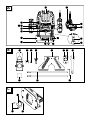
Features
Fig. A:
Speed preselection
Handle
Safety lock-out
ON/OFF switch
Collet chuck 8 mm
Union nut
Locking screw
Guide rail
9a
Holes for the dust extraction adapter
Base plate
Skid plate
Step stop
Spindle locking button
Locking screw
Depth stop
Milling depth adjustment scale
Dial (fine milling depth adjustment)
Fig. B:
Dust extraction adapter
Screw
Collet chuck 6 mm
Centring point
Rip fence
Copy sleeve
Race
Open-ended spanner with slotted hole
Hex key
Sliding rod with screw for rip fence
Reducer
Fig. D:
Rounding cutter Ø 22 mm / R 6.3 mm
Profile cutter Ø 25 mm / R 4 mm
Chamfer milling cutter Ø 22 mm / R 6.3 mm
V-slot milling cutter Ø 12,7mm / angle 90°
Slotting cutter Ø 6mm
Slotting cutter Ø 12mm
Fig. F:
Clamping lever
Package contents
1 router
1 open-end spanner with slotted hole
1 collet chuck 6 mm
1 collet chuck 8 mm (mounted)
1 dust extraction adapter
1 reducer
1 rip fence with 2 guides
1 copy sleeve with 2 screws
1 centring point
1 cutter set, 6 pieces
1 hex key
1 set of operating instructions

POF 1200 D3
GB
│
IE
│
NI
│
CY
│
3 ■
Technical specifications
Rated power input: 1200W
Rated voltage: 230V∼, 50Hz
Rated no-load speed: n
0
11000–30000 rpm
Max. operating speed
(milling cutter) n
max
35000 rpm
Milling basket stroke: 55 mm
Tool holder: 6/8 mm
Protection class: II /
(double insulation)
Noise emission value:
Noise measurement value determined in accordance
with EN 62841. The A-rated noise level of the
power tool is typically as follows:
Sound pressure level: L
pA
= 86.7 dB (A)
Uncertainty: K
pA
= 3 dB
Sound power level: L
WA
= 97.7 dB (A)
Uncertainty K: K
WA
= 3 dB
Wear hearing protection!
Vibration emission value:
Total vibration values (vector total of three direc-
tions) determined in accordance with EN 62841:
Hand/arm vibration a
h
= 4.3 m/s
2
Uncertainty K = 1.5 m/s
2
NOTE
► The vibration emission values and the noise
emission values given in these instructions
have been measured in accordance with
a standardised test procedure and can be
used for comparison of the power tool with
another tool.
► The specified total vibration values and the
noise emission values can also be used to
make a provisional load estimate.
WARNING!
► Depending on the manner in which the power
tool is being used, and in particular the kind of
workpiece that is being worked, the vibration
and noise emission values can deviate from
the values given in these instructions during
actual use of the power tool.
► Try to keep the load as low as possible.
Measures to reduce the vibration load are,
e.g. wearing gloves and limiting the working
time. Wherein all states of operation must be
included (e.g. times when the power tool is
switched off and times where the power tool is
switched on but running without load).
General power tool
safety warnings
WARNING!
► Read all safety warnings, instructions, illust-
rations and specifications provided with this
power tool. Failure to follow all instructions
listed below may result in electric shock, fire
and/or serious injury.
Save all warnings and instructions for future
reference.
The term "power tool" in the warnings refers to your
mains-operated (corded) power tool or battery-
operated (cordless) power tool.
1. Work area safety
a) Keep work area clean and well lit.
Cluttered or dark areas invite accidents.
b) Do not operate power tools in explosive
atmospheres, such as in the presence of flam-
mable liquids, gases or dust. Power tools create
sparks which may ignite the dust or fumes.
c) Keep children and bystanders away while
operating a power tool. Distractions can cause
you to lose control.

POF 1200 D3
■ 4
│
GB
│
IE
│
NI
│
CY
2. Electrical safety
a) Power tool plugs must match the outlet.
Never modify the plug in any way.
Do not use any adapter plugs with earthed
(grounded) power tools. Unmodified plugs
and matching outlets will reduce risk of electric
shock.
b) Avoid body contact with earthed or grounded
surfaces, such as pipes, radiators, ranges and
refrigerators. There is an increased risk of elec-
tric shock if your body is earthed or grounded.
c) Do not expose power tools to rain or wet
conditions. Water entering a power tool will
increase the risk of electric shock.
d) Do not abuse the cord. Never use the cord
for carrying, pulling or unplugging the power
tool. Keep cord away from heat, oil, sharp
edges or moving parts. Damaged or entangled
cords increase the risk of electric shock.
e) When working outdoors with an electrical
power tool always use extension cords that
are also suitable for use outdoors. Use of a
cord suitable for outdoor use reduces the risk
of electric shock.
f) If operating a power tool in a damp location
is unavoidable, use a residual current device
(RCD) protected supply. Use of an RCD re-
duces the risk of electric shock.
3. Personal safety
a) Stay alert, watch what you are doing and
use common sense when operating a power
tool. Do not use a power tool while you are
tired or under the influence of drugs, alcohol
or medication. A moment of inattention while
operating power tools may result in serious
personal injury.
b) Use
personal protective equipment. Always
wear eye protection. Protective equipment such
as a dust mask, non-skid safety shoes, hard hat
or hearing protection used for appropriate condi-
tions will reduce personal injuries.
c) Prevent unintentional starting. Ensure the
switch is in the off-position before connecting
to power source and/or battery pack, picking
up or carrying the tool. Carrying power tools
with your finger on the switch or energising
power tools that have the switch on invites
accidents.
d) Remove any adjusting key or wrench before
turning the power tool on. A wrench or a key
left attached to a rotating part of the power tool
may result in personal injury.
e) Do not overreach. Keep proper footing and
balance at all times. This enables better control
of the power tool in unexpected situations.
f) Dress properly. Do not wear loose clothing or
jewellery. Keep your hair and clothing away
from moving parts. Loose clothes, jewellery or
long hair can be caught in moving parts.
g) If devices are provided for the connection of
dust extraction and collection facilities, ensure
these are connected and properly used. Use of
dust collection can reduce dust-related hazards.
h) Do not allow yourself to get lulled into a false
sense of security and do not ignore the safety
regulations for power tools, even if you are
familiar with the power tool after repeated
use. A careless action can cause severe injury
within a fraction of a second.

POF 1200 D3
GB
│
IE
│
NI
│
CY
│
5 ■
4. Power tool use and care
a) Do not force the power tool. Use the correct
power tool for your application. The correct
power tool will do the job better and safer at
the rate for which it was designed.
b) Do not use the power tool if the switch does
not turn it on and off. Any power tool that can-
not be controlled with the switch is dangerous
and must be repaired.
c) Disconnect the plug from the power source
and/or remove the battery pack, if detacha-
ble, from the power tool before making any
adjustments, changing accessories, or storing
power tools. Such preventive safety measures
reduce the risk of starting the power tool acci-
dentally.
d) Store idle power tools out of the reach of
children and do not allow persons unfamiliar
with the power tool or these instructions to
operate the power tool. Power tools are dan-
gerous in the hands of untrained users.
e) Maintain power tools and accessories. Check
for misalignment or binding of moving parts,
breakage of parts and any other condition
that may affect the power tool’s operation.
If damaged, have the power tool repaired
before use. Many accidents are caused by
poorly maintained power tools.
f) Keep cutting tools sharp and clean. Properly
maintained cutting tools with sharp cutting
edges are less likely to bind and are easier to
control.
g) Use the power tool, accessories and acces-
sory tools etc. in accordance with these
instructions, taking into account the working
conditions and the work to be performed.
Use of the power tool for operations different
from those intended could result in a hazardous
situation.
h) Keep handles and grasping surfaces dry,
clean and free from oil and grease. Slippery
handles and grasping surfaces do not allow for
safe handling and control of the tool in unex-
pected situations.
5. Service
a) Have your power tool serviced by a qualified
repair person using only identical replace-
ment parts. This will ensure that the safety of
the power tool is maintained.
Safety instructions for routers
a) Always hold the appliance using the insulated
handle surfaces since the milling cutter can
damage its own power cord.
Contact with a live wire may make exposed
metal parts of the power tool live and could
give the operator an electric shock.
b) Fix and secure the workpiece to a stable base
using clamps or other methods. If you only
hold the workpiece in your hands or against
your body it will remain unstable, and this can
result in loss of control.
■ Wear a dust mask.

POF 1200 D3
■ 6
│
GB
│
IE
│
NI
│
CY
Supplementary notes
■ The maximum speed of the milling tool used
must be at least as high as the maximum
speed specified for the power tool. Acces-
sories which rotate faster than the maximum
permissible rate can be destroyed.
■ Cutters or other accessories must fit exactly
into the collet chuck (shank diameter 6/8 mm)
of your power tool. Milling tools which do not
fit precisely into the collet chuck of the power
tool will rotate unevenly, vibrate severely and
can lead to a loss of control.
■ Always switch on the electrical power tool
before applying it to the workpiece. Otherwi-
se, there is a risk of a kickback if the accessory
tool gets caught in the workpiece.
■ Keep your hands clear of the milling area and
the milling tool. Hold the auxiliary handle or
motor housing with your other hand. If both
hands are being used to hold the milling machine,
neither can be injured by the milling cutter.
■ Never mill over metal objects, nails or screws.
The milling cutter can be damaged and it can
lead to increased vibrations.
■ Use a suitable detector to locate hidden utility
lines or consult your local utility company.
Contact with electrical lines can cause fires or
electric shocks. Damage to a gas pipeline can
lead to an explosion. Drilling into a water pipe
can cause damage to property.
■ The maximum speed indicated on the tool must
not be exceeded.
■ Tools with visible cracks must be discarded.
Original accessories/auxiliary
equipment
■ Only use the accessories and additional
equipment that are specified in the operating
instructions and are compatible with the
appliance.
Before use
Milling cutter set/areas of use
Original accessories included in delivery:
For profiling:
Rounding cutter Ø 22 mm / R 6.3 mm
Profile cutter Ø 25 mm / R 4 mm
Chamfer milling cutter
Ø 22 mm / R 6.3 mm
V-slot milling cutter
Ø 12,7mm / angle 90°
For linking:
Slotting cutter Ø 6mm
Slotting cutter Ø 12mm
NOTE
► If the ball bearing of a milling cutter has
become loose, tighten it with the hex key
supplied with the cutter set.

POF 1200 D3
GB
│
IE
│
NI
│
CY
│
7 ■
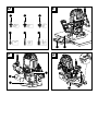
Inserting a milling tool
♦ Press the spindle locking button and hold it
down.
♦ Undo the union nut
by turning it anticlockwi-
se with the open-ended spanner .
♦ Release the spindle locking button
.
♦ Now insert the milling tool.
This must be inserted to a depth of at least
20 mm.
♦ Press the spindle locking button
and hold it
down.
♦ Tighten the union nut
using the open-ended
spanner .
♦ Release the spindle locking button
.
Connecting the dust extraction adap-
ter
♦ Fit the dust extraction adapter onto the holes
provided for the dust extraction adapter
9a
.
♦ Screw the screws
into the underside of the
base plate .
♦ Attach an approved dust and sawdust extractor
to the dust extraction adapter
(see fig. F).
Reducer
Connecting:
♦ Push the reducer
into the dust extraction
adapter .
♦ Push the hose of a suitable of vacuum cleaning
appliance (e.g. a workshop vacuum) onto the
reducer
.
Removal:
♦ Pull the hose of the vacuum cleaner off the
reducer
.
♦ Remove the reducer
.
Changing the collet chuck
NOTE
► All of the cutters in the supplied cutter set are
equipped with an 8 mm shank.
Use the pre-assembled collet chuck
(8 mm)
with them. When using milling cutters with
a 6 mm shank, replace the collet chuck as
described below.
♦ Press the spindle locking button
and hold it
down.
♦ Undo the union nut anticlockwise with the open-
ended spanner
until the collet chuck (8
mm) can be removed.
♦ Fit the collet chuck
(6 mm).
ATTENTION! Do not tighten the union nut
with the open-ended spanner
unless a milling
tool is fitted. Otherwise, the collet chuck may be
damaged.
♦ Release the spindle locking button
.
Fitting the rip fence
NOTE
► The oblong holes of the open-ended spanner
can be used to counter tighten the screws.
♦ Unscrew both screws of the sliding rods
with
a Phillips screwdriver.
♦ Fasten the sliding rods
onto the rip fence
and tighten the screws.

POF 1200 D3
■ 8
│
GB
│
IE
│
NI
│
CY
Setting up
Switching on and off
Switching on:
♦ Press the safety lock-out
and hold it down.
♦ Press the ON/OFF switch
. Once the ma-
chine is running, you can release the safety
lock-out .
Switching off:
♦ Release the ON/OFF switch
.
Preselecting the rotation speed
♦ Set the required speed using the adjusting
wheel for speed preselection .
1–2 = low speed
3–4 = average speed
5–7 = high speed
Setting the milling depth
♦ Make sure that the clamping lever is locked.
If it is released, turn it anticlockwise until it is
locked.
♦ Place the appliance onto the workpiece.
♦ Rotate the step stop
until it engages in the
lowest position (0 mm).
The depth stop is now in line with the lowest
position (0 mm).
♦ Undo the locking screw
.
♦ Release the clamping lever
by turning it
clockwise and pushing the appliance down-
wards until the milling machine is touching the
surface of the workpiece.
♦ Lock the clamping lever
by turning it antic-
lockwise.
♦ Slide the depth stop
downwards until it
reaches the lowest position (0 mm) of the step
stop .
♦ Set the depth stop
to the desired milling
depth, tighten the locking screw .
♦ Now, release the clamping lever
and raise
the appliance again.
♦ Check the milling depth by means of a practical
test.
Re-adjusting the milling depth
♦ The milling depth can be readjusted using the
dial .
♦ Release the clamping lever
by turning it
clockwise and pushing the appliance down-
wards until the depth stop on the step stop
is reached.
♦ Lock the clamping lever
by turning it antic-
lockwise.
♦ Set the milling depth with the dial
.
♦ Release the clamping lever
by turning it
clockwise and raise the appliance again. Check
the milling depth by means of another practical
test.
Setting the milling depth with the
step stop
NOTE
► The step stop
can be used for greater
milling depths in several stages with less chip
removal.
♦ Set the desired milling depth to the lowest step
(0 mm) of the step stop
(as described abo-
ve).
♦ Then set the higher levels for the first machining
steps.
♦ Check the milling depth by means of a practical
test.

POF 1200 D3
GB
│
IE
│
NI
│
CY
│
9 ■
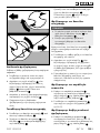
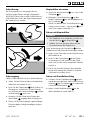
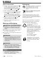
Milling direction
The milling process must always be carried out
against the direction of rotation of the milling cutter
(reverse rotation). ATTENTION: When milling in
the direction of rotation (synchronous running), the
power tool can be ripped out of your hand.
Milling operation
Adjust the desired milling depth as described
above.
♦ Place the appliance onto the workpiece and
switch it on.
♦ Release the clamping lever
by turning it
clockwise and pushing the appliance down-
wards until the depth stop sits on the step
stop .
♦ Lock the appliance by turning the clamping
lever
anticlockwise.
♦ Carry out the milling process at a uniform speed
and contact pressure.
Fitting the copy sleeve
♦ Fit the copy sleeve into the skid plate
from below.
♦ Fasten the copy sleeve
onto the base plate
using the two screws of the dust extraction
adapter.
Ensure that you insert the copy sleeve the
right way around – the race must be facing
downwards (see fig. C).
Milling with the copy sleeve
NOTE
► The template must be at least as high as the
race
of the copy sleeve .
► Select a smaller cutter than the inner diameter
of the copy sleeve.
You can use a copy sleeve
to transfer templates
onto the workpiece.
♦ Place the router with the copy sleeve on the
template.
♦ Release the clamping lever
by turning it
clockwise and lower the appliance until the
previously set milling depth is reached.
♦ Now guide the appliance around the template
with the copy sleeve protruding. Do not exert
excessive pressure when working.
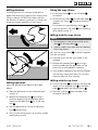
Milling with the rip fence
♦ Push the rip fence according to the required
dimension into the guide rails on the base
plate and tighten the locking screws .
♦ Place the rip fence
onto the edge of the
workpiece (see Fig. E).

POF 1200 D3
■ 10
│
GB
│
IE
│
NI
│
CY
Milling with a compass
♦ To do this, slide the rip fence turned by
180° (see fig. G) into the guide rails on
the base plate according to the required
dimension.
♦ Tighten the locking screws
.
♦ Set the centring point
into the rip fence
and tighten it using the wing screw (see fig. G).
Counter the centring point to tighten it using
the oblong hole of the open-ended spanner .
♦ Stab the centring point
into the marked cen-
tre point of a circle.
♦ Check the setting by means of a practical test.
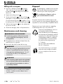
Maintenance and cleaning
WARNING! RISK OF INJURY!
■ Switch the appliance off and remove the
power plug before starting any work on
the appliance.
■ The appliance must always be kept clean, dry
and free from oil or grease.
■ Use a soft, dry cloth to clean the housing.
WARNING!
■ Have the power tool repaired by the service
centre or a qualified electrician and only
using genuine replacement parts. This will
ensure that the safety of the appliance is
maintained.
WARNING!
■ If the connecting cable needs to be replaced,
this must be carried out by the manufacturer
or an authorised representative in order to
avoid safety hazards.
NOTE
► Replacement parts not listed (such as carbon
brushes, switches) can be ordered via our
service centre.
Disposal
The packaging is made from environmen-
tally friendly material and can be dispo-
sed of at your local recycling plant.
Do not dispose of power tools in
your normal domestic waste!
European Directive 2012/19/EU requires that
worn-out power tools be collected separately and
recycled in an environmentally compatible manner.
Please consult your local authorities regarding
suitable disposal of worn out power tools.
Dispose of the packaging in an envi-
ronmentally friendly manner.
Note the labelling on the packaging
and separate the packaging material
components for disposal if necessary.
The packaging material is labelled
with abbreviations (a) and numbers
(b) with the following meanings:
1–7: plastics,
20–22: paper and cardboard,
80–98: composites
Your local community or municipal
authorities can provide information
on how to dispose of the worn-out
product.

POF 1200 D3
GB
│
IE
│
NI
│
CY
│
11 ■
Kompernass Handels GmbH
warranty
Dear Customer,
This appliance has a 3-year warranty valid from
the date of purchase. If this product has any faults,
you, the buyer, have certain statutory rights. Your
statutory rights are not restricted in any way by the
warranty described below.
Warranty conditions
The warranty period starts on the date of purchase.
Please keep your receipt in a safe place. This will
be required as proof of purchase.
If any material or manufacturing fault occurs within
three years of the date of purchase of the product,
we will either repair or replace the product for you
or refund the purchase price (at our discretion).
This warranty service requires that you present the
defective appliance and the proof of purchase (re-
ceipt) within the three-year warranty period, along
with a brief written description of the fault and of
when it occurred.
If the defect is covered by the warranty, your pro-
duct will either be repaired or replaced by us. The
repair or replacement of a product does not signify
the beginning of a new warranty period.
Warranty period and statutory claims for
defects
The warranty period is not prolonged by repairs
effected under the warranty. This also applies to
replaced and repaired components. Any damage
and defects present at the time of purchase must
be reported immediately after unpacking. Repairs
carried out after expiry of the warranty period shall
be subject to a fee.
Scope of the warranty
This appliance has been manufactured in ac-
cordance with strict quality guidelines and inspec-
ted meticulously prior to delivery.
The warranty covers material faults or production
faults. The warranty does not extend to product
parts subject to normal wear and tear or to fragile
parts which could be considered as consumable
parts such as switches, batteries or parts made of
glass.
The warranty does not apply if the product has
been damaged, improperly used or improper-
ly maintained. The directions in the operating
instructions for the product regarding proper use
of the product are to be strictly followed. Uses
and actions that are discouraged in the operating
instructions or which are warned against must be
avoided.
This product is intended solely for private use and
not for commercial purposes. The warranty shall be
deemed void in cases of misuse or improper hand-
ling, use of force and modifications / repairs which
have not been carried out by one of our authorised
Service centres.

POF 1200 D3
■ 12
│
GB
│
IE
│
NI
│
CY
Warranty claim procedure
To ensure quick processing of your case, please
observe the following instructions:
■ Please have the till receipt and the item num-
ber (e.g.IAN
322471
) available as proof of
purchase.
■ You will find the item number on the type plate
on the product, an engraving on the product,
on the front page of the operating instructions
(below left) or on the sticker on the rear or
bottom of the product.
■ If functional or other defects occur, please
contact the service department listed either by
telephone or by e-mail.
■ You can return a defective product to us free of
charge to the service address that will be pro-
vided to you. Ensure that you enclose the proof
of purchase (till receipt) and information about
what the defect is and when it occurred.
You can download these instructions
along with many other manuals,
product videos and installation
software at www.lidl-service.com.
This QR code will take you directly
to the Lidl service page (www.lidl-service.com)
where you can open your operating instructions by
entering the item number (IAN) 322471.
Service
Service Great Britain
Tel.: 0800 404 7657
E-Mail: kom[email protected]
Service Ireland
Tel.: 1890 930 034
(0,08 EUR/Min., (peak))
(0,06 EUR/Min., (off peak))
E-Mail: kom[email protected]
CY
Service Cyprus
Tel.: 8009 4409
E-Mail: kom[email protected]
IAN 322471_1901
Importer
Please note that the following address is not the
service address. Please use the service address
provided in the operating instructions.
KOMPERNASS HANDELS GMBH
BURGSTRASSE 21
44867 BOCHUM
GERMANY
www.kompernass.com

POF 1200 D3
GB
│
IE
│
NI
│
CY
│
13 ■
Translation of the original Conformity Declaration
We, KOMPERNASS HANDELS GMBH, documents officer: Mr. Semi Uguzlu, BURGSTR. 21,
44867 BOCHUM, Germany, hereby declare that this product complies with the following standards,
normative documents and EC directives:
Machinery Directive
(2006/42/EC)
Electromagnetic Compatibility
(2014/30/EU)
RoHS Directive
(2011/65/EU)*
* The manufacturer bears the full responsibility for compliance with this conformity declaration.
The object of the declaration described above complies with the requirements of the Directive
2011/65/EU of the European Parliament and Council of 8 June 2011 on the limitations of use
of certain dangerous substances in electrical and electronic appliances.
Applied harmonised standards:
EN 62841-1:2015
EN 62841-2-17:2017
EN 55014-1:2017
EN 55014-2:2015
EN 61000-3-2:2014
EN 61000-3-3:2013
EN 50581:2012
Type designation of the machine: Router POF 1200 D3 KAT
Year of manufacture: 06 - 2019
Serial number: IAN 322471_1901
Bochum, 05/06/2019
Semi Uguzlu
- Quality Manager -
The right to effect technical changes in the context of further development is reserved.

POF 1200 D3
■ 14
│
GB
│
IE
│
NI
│
CY

POF 1200 D3
GR
│
CY
│
15 ■
Περιεχόμενα
Εισαγωγή .......................................................16
Προβλεπόμενη χρήση ....................................................... 16
Εξοπλισμός ............................................................... 16
Παραδοτέος εξοπλισμός .....................................................16
Τεχνικά χαρακτηριστικά ...................................................... 17
Γενικές υποδείξεις ασφαλείας για τα ηλεκτρικά εργαλεία ................17
1. Ασφάλεια στον χώρο εργασίας .............................................. 18
2. Ηλεκτρική ασφάλεια .......................................................18
3. Ασφάλεια ατόμων ........................................................18
4. Χρήση και χειρισμός του ηλεκτρικού εργαλείου ................................. 19
5. Σέρβις .................................................................19
Υποδείξεις ασφαλείας για κάθετες φρέζες ....................................... 20
Συμπληρωματικές οδηγίες ....................................................20
Γνήσια εξαρτήματα/πρόσθετες συσκευές ........................................ 20
Πριν από τη θέση σε λειτουργία .....................................20
Σετ φρέζας / Τομείς χρήσης .................................................. 20
Σύνδεση αντάπτορα αναρρόφησης ............................................21
Εξάρτημα συστολής .........................................................21
Αλλαγή λαβίδας σύσφιξης ...................................................21
Τοποθέτηση παράλληλου αναστολέα ...........................................21
Θέση σε λειτουργία ...............................................21
Ενεργοποίηση και απενεργοποίηση .............................................21
Προεπιλογή αριθμού στροφών ................................................22
Ρύθμιση βάθους φρεζαρίσματος ...............................................22
Επαναρύθμιση βάθους φρεζαρίσματος .........................................22
Ρύθμιση βάθους φρεζαρίσματος με τον βαθμιδωτό αναστολέα .......................22
Κατεύθυνση φρεζαρίσματος .................................................. 22
Διαδικασία φρεζαρίσματος ...................................................23
Τοποθέτηση δακτυλίου αντιγραφής .............................................23
Φρεζάρισμα με τον δακτύλιο αντιγραφής ........................................ 23
Φρεζάρισμα με τον παράλληλο αναστολέα ......................................23
Φρεζάρισμα με διαβήτη κυκλικού φρεζαρίσματος .................................23
Συντήρηση και καθαρισμός ........................................24
Απόρριψη ......................................................24
Εγγύηση της Kompernass Handels GmbH ............................25
Σέρβις ................................................................... 26
Εισαγωγέας ............................................................... 26
Μετάφραση της Πρωτότυπης Δήλωση συμμόρφωσης ...................27

POF 1200 D3
■ 16
│
GR
│
CY
ΚΑΘΕΤΗ ΦΡΕΖΑ POF 1200 D3
Εισαγωγή
Σας συγχαίρουμε για την αγορά της νέας σας
συσκευής. Το προϊόν που αποκτήσατε είναι
ένα προϊόν υψηλής ποιότητας. Οι οδηγίες
χρήσης αποτελούν τμήμα αυτού του προϊόντος.
Περιλαμβάνουν σημαντικές υποδείξεις για την
ασφάλεια, τη χρήση και την απόρριψη. Πριν
από τη χρήση του προϊόντος, εξοικειωθείτε με
όλες τις υποδείξεις χειρισμού και ασφάλειας.
Χρησιμοποιείτε το προϊόν αποκλειστικά όπως
περιγράφεται και για τους αναφερόμενους
τομείς χρήσης. Παραδίδετε όλα τα έγγραφα σε
περίπτωση παράδοσης του προϊόντος σε τρίτους.
Προβλεπόμενη χρήση
Η συσκευή προορίζεται για φρεζάρισμα, καθώς
και φρεζάρισμα αντιγραφής, εγκοπών, ακμών,
προφίλ και διαμήκων οπών σε ξύλο, πλαστικό
και υλικά ελαφριών κατασκευών, επάνω σε μια
σταθερή επιφάνεια απόθεσης. Η συσκευή δεν είναι
κατάλληλη για λειτουργία σε εξωτερικούς χώρους.
Κάθε άλλη χρήση ή μετατροπή της συσκευής
θεωρείται μη σύμφωνη με τους κανονισμούς και
ενέχει σημαντικούς κινδύνους ατυχημάτων. Δεν
προορίζεται για επαγγελματική χρήση.
Εξοπλισμός
Εικ. A:
Προεπιλογή αριθμού στροφών
Χειρολαβή
Φραγή ενεργοποίησης
Διακόπτης ON/OFF
Λαβίδα σύσφιξης 8 mm
Περικόχλιο-ρακόρ
Βίδα ρύθμισης
Ράγα-οδηγός
9a
Οπές για τον αντάπτορα αναρρόφησης
Πλάκα βάσης
Πλάκα ολίσθησης
Βαθμιδωτός αναστολέας
Πλήκτρο ασφάλισης ατράκτου
Βίδα ασφάλισης
Αναστολέας βάθους
Κλίμακα ρύθμισης του βάθους φρεζαρίσματος
Περιστρεφόμενος ρυθμιστής (Διάταξη ακριβούς
ρύθμισης βάθους φρεζαρίσματος)
Εικ. B:
Αντάπτορας αναρρόφησης
Βίδα
Λαβίδα σύσφιξης 6 mm
Ακμή κεντραρίσματος
Παράλληλος αναστολέας
Δακτύλιος αντιγραφής
Δακτύλιος κίνησης
Διπλό κλειδί με επιμήκη οπή
Εσωτερικό εξάγωνο κλειδί
Ράβδος ολίσθησης με βίδα παράλληλου
αναστολέα
Εξάρτημα συστολής
Εικ. D:
Φρέζα στρογγυλέματος Ø 22 mm / R 6,3 mm
Φρέζα προφίλ Ø 25 mm / R 4 mm
Φρέζα κοιλοτήτων Ø 22 mm / R 6,3 mm
Φρέζα αυλάκωσης σχήματος V Ø 12,7 mm /
Γωνία 90°
Φρέζα αυλάκωσης Ø 6 mm
Φρέζα αυλάκωσης Ø 12 mm
Εικ. F:
Μοχλός σύσφιξης
Παραδοτέος εξοπλισμός
1 Κάθετη φρέζα
1 Διπλό κλειδί με επιμήκη οπή
1 Λαβίδα σύσφιξης 6 mm
1 Λαβίδα σύσφιξης 8 mm (συναρμολογημένη)
1 Αντάπτορας αναρρόφησης
1 Εξάρτημα συστολής
1 Παράλληλος αναστολέας με 2 οδηγούς
1 Δακτύλιος αντιγραφής με 2 βίδες
1 Ακμή κεντραρίσματος
1 Σετ φρεζών, 6 τεμάχια
1 Εξάγωνο κλειδί
1 Εγχειρίδιο οδηγιών χρήσης
Seite laden ...
Seite laden ...
Seite laden ...
Seite laden ...
Seite laden ...
Seite laden ...
Seite laden ...
Seite laden ...
Seite laden ...
Seite laden ...
Seite laden ...
Seite laden ...
Seite laden ...
Seite laden ...
Seite laden ...
Seite laden ...
Seite laden ...
Seite laden ...
Seite laden ...
Seite laden ...
Seite laden ...
Seite laden ...
Seite laden ...
Seite laden ...
Seite laden ...
Seite laden ...
Seite laden ...
-
 1
1
-
 2
2
-
 3
3
-
 4
4
-
 5
5
-
 6
6
-
 7
7
-
 8
8
-
 9
9
-
 10
10
-
 11
11
-
 12
12
-
 13
13
-
 14
14
-
 15
15
-
 16
16
-
 17
17
-
 18
18
-
 19
19
-
 20
20
-
 21
21
-
 22
22
-
 23
23
-
 24
24
-
 25
25
-
 26
26
-
 27
27
-
 28
28
-
 29
29
-
 30
30
-
 31
31
-
 32
32
-
 33
33
-
 34
34
-
 35
35
-
 36
36
-
 37
37
-
 38
38
-
 39
39
-
 40
40
-
 41
41
-
 42
42
-
 43
43
-
 44
44
-
 45
45
-
 46
46
-
 47
47


Parkside POF 1200 D3 Translation Of The Original Instructions
- Kategorie
- Elektrowerkzeuge
- Typ
- Translation Of The Original Instructions
in anderen Sprachen
- English: Parkside POF 1200 D3
Verwandte Papiere
-
Parkside POF 1200 D3 Translation Of The Original Instructions
-
Parkside POF 1200 A1 Operation and Safety Notes
-
-
-
-
Parkside 1200 A1 Operation and Safety Notes
-
Parkside POF 1200 C2 Translation Of The Original Instructions
-
Parkside POF 1200 B2 Original Instructions Manual
-
Kompernass POF1300 Benutzerhandbuch
-
Sonstige Unterlagen
-
Ferm FBF 1200 Bedienungsanleitung
-
Bosch GOF 2000 CE Bedienungsanleitung
-
Bosch POF 1200 Benutzerhandbuch
-
Bosch POF 1200 AE Benutzerhandbuch
-
Westfalia 87 46 87 Benutzerhandbuch
-
Mafell LO 55 Bedienungsanleitung
-
Hitachi M 8V2 Bedienungsanleitung
-
-
Festool PF 1200 E-Plus Dibond Bedienungsanleitung
-