Parkside 1200 A1 Operation and Safety Notes
- Typ
- Operation and Safety Notes

IAN 90981
ROUTER POF 1200 A1
OBERFRÄSE
Bedienungs- und Sicherheitshinweise
Originalbetriebsanleitung
ΚΑΘΕΤΗ ΦΡΕΖΑ
Υποδείξει χειρισού και ασφαλεία
Μετάφραση των αυθεντικών οδηγιών λειτουργίας
ROUTER
Operation and Safety Notes
Translation of original operation manual

GB / CY Operation and Safety Notes Page 5
GR / CY Υποδείξει χειρισού και ασφαλεία Σελίδα 15
DE / AT / CH Bedienungs- und Sicherheitshinweise Seite 27
Before reading, unfold both pages containing illustrations and familiarise yourself with all functions of the
device.
Πριν ξεκινήσετε την ανάγνωση, ανοίξτε τι δυο σελίδε ε τι εικόνε και εξοικειωθείτε ε όλε τι
λειτουργίε τη συσκευή.
Klappen Sie vor dem Lesen die beiden Seiten mit den Abbildungen aus und machen Sie sich anschließend
mit allen Funktionen des Gerätes vertraut.

DC
272625242321
A
B
4
5
6
2
3
7
8
9
13
15
10
11
12
14
16
2
18
17
20
19
5
6
26 222522
29
1
22
30 28
31

F
G
E
H
I J
35 3736
32 33 34
40
38 39
42
41
43

5 GB/CY
Table of contents
Introduction
Intended use ........................................................................................................................................ Page 6
Features ...............................................................................................................................................Page 6
Scope of delivery ................................................................................................................................Page 6
Technical Data ....................................................................................................................................Page 7
General safety advice for electrical power tools
1. Workplace safety ...........................................................................................................................Page 7
2. Electrical safety ............................................................................................................................... Page 7
3. Personal safety ................................................................................................................................Page 8
4. Careful handling and use of electrical power tools .....................................................................Page 8
5. Service .............................................................................................................................................Page 9
Safety notices specific to routers ........................................................................................................ Page 9
Supplementary Instructions .................................................................................................................Page 9
Original accessories / tools ................................................................................................................Page 9
Start-up
Router set / Applications .....................................................................................................................Page 10
Using the router tool ...........................................................................................................................Page 10
Attaching the extractor adapter ......................................................................................................... Page 10
Reducer ................................................................................................................................................Page 10
Changing the collet .............................................................................................................................Page 10
Fitting the guide fence .........................................................................................................................Page 10
Operation
Switching on and off ........................................................................................................................... Page 10
Presetting the speed ............................................................................................................................ Page 11
Set the milling depth ...........................................................................................................................Page 11
Readjust the Milling depth ..................................................................................................................Page 11
Set the milling depth with the step stop .............................................................................................Page 11
Milling direction ..................................................................................................................................Page 11
Milling Process ....................................................................................................................................Page 12
Set the copy casing .............................................................................................................................Page 12
Milling with the copy casing ..............................................................................................................Page 12
Milling with a rip fence ....................................................................................................................... Page 12
Milling with a circular compass .........................................................................................................Page 12
Maintenance and Cleaning ..............................................................................................Page 12
Warranty .........................................................................................................................................Page 12
Disposal ............................................................................................................................................Page 13
Declaration of conformity / Manufacturer ..........................................................Page 14

6 GB/CY
Introduction / General safety advice for electrical power tools
Introduction
Router POF 1200 A1
Introduction
We congratulate you on the purchase of your new
device. You have chosen a high quality product. The
instructions for use are part of the product. They
contain important information concerning safety,
use and disposal. Before using the product, please
familiarise yourself with all of the safety information
and instructions for use. Only use the unit as de
scribed
and for the specified applications. If you pass the
product on to anyone else, please ensure that you
also pass on all the documentation with it.
Intended use
This device is intended to mill grooves, edges, pro-
files and slots on a wooden, plastic or light surface,
as well as copy milling. This device is not intended
for outdoor use. Any other uses, and / or modifica-
tions to the appliance, are deemed to be improper
usage and may result in serious physical injury. Not
for commercial applications.
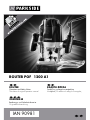
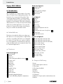
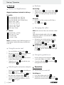
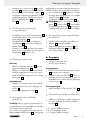
Features
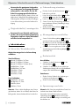
Front view figure A
1
Speed setting
2
Handle
3
Union nut
4
Collet 8 mm (preinstalled in union nut
3
)
5
Locking screw
6
Guide rail
7
Base plate
8
Sliding plate
9
Step stop
10
Spindle-lock key
11
Lock screw
12
Depth stop
13
Index indicator
14
Dial milling depth adjustment
15
Control dial (milling depth-fine adjustment)
Back view figure B
16
Clamping lever
17
Router tool
18
Drilling extractor adapter
19
ON / OFF switch
20
Start lockout
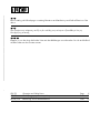
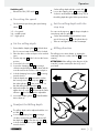
Parts figure C
21
Extractor
22
Screw
23
Collet 6 mm
24
Rip fence
25
Thrust ring
26
Copy casing
27
Open-ended spanner with slot
28
Reducer
29
Sliding bar with screw for rip fence
24
30
Centring pin
31
Socket head wrench
Router set figure D
32
Round and profile cutter 24.7 mm
33
Round and profile cutter 28.6 mm
34
Round and profile cutter 28.6 mm (R-4)
35
Hollow cutter 12 mm
36
Hollow cutter 24.7 mm
37
V-groove cutter 9.5 mm
38
V-groove cutter 16 mm
39
Bevel cutter 32 mm
40
Dovetail cutter 14.3 mm
41
Flush cutter 12.7 mm
42
Slot cutter 6 mm
43
Slot cutter 12 mm
Scope of delivery
1 Router
1 Open-ended spanner with slot
1 Collet 6 mm
1 Collet 8 mm (installed)
1 Extractor
1 Rip fence
1 Copy casing
1 Centring pin
1 Milling set 12 parts (with socket head wrench)
1 Reducer

7 GB/CY
Introduction / General safety advice for electrical power tools
Introduction
1 Socket head wrench
1 Set of operating instructions
Technical Data
Rated power input: 1200 W
Rated voltage: 230 V∼, 50 Hz
Idle speed: n
0
11000–30000 min
-1
Plunge depth: 55 mm
Tool holder: 6/8 mm
Protection class: II /
Noise and vibration data:
Measured sound value determined according to
EN 60745. The A-rated noise levels of the electrical
power tool are typically at:
Sound pressure level: 84.7 dB(A)
Sound power level: 95.7 dB(A)
Uncertainty K: 3 dB
Wear hearing protection!
Evaluated acceleration, typically:
Hand / arm vibration a
h
= 6.437 m / s²
Instability K = 1.5 m / s²
The vibration level specified in
these instructions was measured in accordance with
an EN 60745 standardised measurement process
and can be used to compare equipment. The vibra-
tion emission value specified can also serve as a
preliminary assessment of the exposure.
The vibration level will change according to the ap-
plication of the electrical tool an in some cases may
exceed the value specified in these instructions. Re-
gularly using the electric tool in such a way may
make it easy to underestimate the vibration.
Note: If you wish to make an accurate assessment
of the vibration loads experienced during a particu-
lar period of working, you should also take into
account the intervening periods of time when the
device is switched off or is running but is not actual-
ly in use. This can result in a much lower vibration
load over the whole of the period of working.
General safety advice for
electrical power tools
Read all the safety advice
and instructions! Failure to observe the safety
advice and instructions may result in electric shock,
fire and / or serious injury.
Keep all the safety advice and instructions
in a safe place for future reference!
The term “electrical tool” used in the safety advice
refers to electrical tools powered by mains electrici-
ty (by means of a mains lead) and electrical tools
powered by rechargeable batteries (without a
mains lead).
1. Workplace safety
a) Keep your working area clean and
well lit. Untidy or poorly lit working areas can
lead to accidents.
b) Do not work with the device in poten-
tially explosive environments in which
there are inflammable liquids, gases
or dusts. Electrical power tools create sparks,
which can ignite dusts or fumes.
c) Keep children and other people away
while you are operating the electrical
tool. Distractions can cause you to lose control
of the device.
2. Electrical safety
a)
The mains plug on the device must match
the mains socket. The plug must not be
modified in any way. Do not use an
adapter plug with devices fitted with
a protective earth. Unmodified plugs and
matching sockets reduce the risk of electric shock.
b) Avoid touching earthed surfaces such
as pipes, radiators, ovens and refrig-
erators with any part of your body.
There is an increased risk of electric shock if
your body is earthed.

8 GB/CY
General safety advice for electrical power tools
General safety advice for electrical power tools
c) Keep the device away from rain or
moisture. Water entering an electrical device
increases the risk of electric shock.
d) Do not use the mains lead for any pur-
pose for which it was not intended,
e.g.
to carry the device, to hang up the de-
vice or to pull the mains plug out of
the mains socket. Keep the mains lead
away from heat, oil, sharp edges or
moving parts of the device. Damaged
or tangled mains leads increase the risk of
electric shock.
e) When working outdoors with an
electrical power tool always use ex-
tension cables that are also approved
for use outdoors. The use of an extension
cable suitable for outdoor use reduces the risk
of electric shock.
f) Use a residual current device (RCD)
for protection if operating the electri-
cal power tool in a moist environment
is unavoidable. The use of an RCD reduces
the risk of electric shock.
3. Personal safety
a) Remain alert at all times, watch what
you are doing and always proceed
with caution. Do not use the device if
you are tired or under the influence of
drugs, alcohol or medication. One mo
ment
of carelessness when using the device can lead
to serious injury.
b) Wear personal protective equipment
and always wear safety glasses. The
wearing of personal protective equipment such
as dust masks, non-slip safety shoes, safety hel-
mets or ear protectors, appropriate to the type
of electrical power tool used and work under-
taken, reduces the risk of injury.
c) Avoid unintentional operation of the
device. Check that the electrical power
tool is switched off before you connect
it to the mains, pick it up or carry it.
Accidents can happen if you carry the device
with your finger on the ON / OFF switch or with
the device switched on.
d) Remove any setting tools or spanners
before you switch the device on. A tool
or spanner left attached to a rotating part of a
device can lead to injury.
e) Avoid placing your body in an unnat-
ural position. Keep proper footing and
balance at all times. By doing this you will
be in a better position to control the device in
unforeseen circumstances.
f) Wear suitable clothing. Do not wear
loose clothing or jewellery. Keep your
hair, clothing and gloves clear of mov-
ing parts. Loose clothing, jewellery or long
hair can become trapped in moving parts.
g) If vacuum dust extraction and collection
devices are fitted do not forget to
check
that they are properly connected and
correctly used. The use of these devices
reduces the hazard presented by dust.
4. Careful handling and use
of electrical power tools
a) Do not overload the device. Always
use an electrical power tool that is
intended for the task you are under-
taking. By using the right electrical power
tool for the job you will work more safely and
achieve a better result.
b) Do not use an electrical power tool if
its switch is defective. An electrical power
tool that can no longer be switched on and off
is dangerous and must be repaired.
c) Pull the mains plug from the socket
before you make any adjustments to
the device, change accessories or when
the device is put away. This precaution is
intended to prevent you from unintentionally
starting the device.
d) When not in use always ensure that
electrical power tools are kept out of
reach of children. Do not let anyone use
the device if he or she is not familiar
with it or has not read the instructions
and advice. Electrical power tools are dan-
gerous when they are used by inexperienced
people.

9 GB/CY
General safety advice for electrical power tools
General safety advice for electrical power tools
e) Look after the device carefully. Check
that moving parts are working prop-
erly and move freely. Check for any
parts that are broken or damaged
enough to detrimentally affect the
functioning of the device. Have dam-
aged parts repaired before you use
the device. Many accidents have their origins
in poorly maintained electrical power tools.
f) Keep cutting tools clean and sharp.
Carefully maintained cutting tools with sharp
cutting edges are less likely to jam and are
easier to control.
g) Use the electrical power tool, accesso-
ries, inserted tools etc. in accordance
with these instructions and advice, and
the stipulations drawn up for this par-
ticular type of device. In doing this, take
into account the working conditions
and the task in hand. The use of electrical
power tools for purposes other than those in-
tended can lead to dangerous situations.
5. Service
a) Have your device repaired at the ser-
vice centre or by qualified specialist
personnel using original manufacturer
parts only. This will ensure that your device
remains safe to use.
S
afety notices specific to routers
Only hold the power tool by the insu-
lated handle areas as the router may
touch the tool’s mains cable. Contact
with a live wire could cause metal parts of the
device to become live and lead to electric shock.
Fix and secure the work piece to a
stable surface using clamps or other
means. When only securing the work piece
by hand or against your body it will remain
unstable, which could lead to loss of control.
Supplementary Instructions
The permissible rotational speed of the
router tool must be at least as high as
the maximum speed indicated on the
electrical power tool. Parts used at higher
than permissible speeds may be ruined.
The router or other parts must fit pre-
cisely in the collet (shaft diameter 6/8)
of your electric power tool. Cutting tools
which do not fit precisely in the collet of the
electric power tool turn unevenly, vibrate strong-
ly and can lead to a loss of control.
Always switch on the electrical power
tool before placing it against the work-
piece. There is also the risk of kickback if the
electric power tool becomes caught in the
work-piece.
Keep your hands away from the cut-
ting area and the router. Keep your
second hand on the additional handle
or on the engine housing. If you hold the
router with both hands, they cannot be injured
by the router.
Never use on metal objects, nails or
screws. The router can become damaged
and this may lead to higher vibrations.
Use suitable detectors in order to look
for hidden supply lines, or consult your
local power authority. Contact with elec-
tric lines can lead to fire and electric shocks.
Damage to a gas line can lead to explosions.
Breaking a water line can cause damages.
Original accessories / tools
U
se only the accessories and attachment
s
detailed in the operating instructions,
or those which are compatible with
the device.

10 GB/CY
Operation
Start-up / Operation
Start-up
Router set / Applications
Original attachment included in delivery:
To profile:
32
Round and profile cutter, 24.7 mm
33
Round and profile cutter, 28.6 mm
34
Round and profile cutter 28.6 mm (R–4)
35
Hollow cutter, 12 mm
36
Hollow cutter, 24.7 mm
37
V-groove cutter, 9.5 mm
38
V-groove cutter, 16 mm
39
Bevel cutter, 32 mm
To connect:
40
Dovetail cutter, 14.3 mm
41
Flush cutter, 12.7 mm
42
Slot cutter, 6 mm
43
Slot cutter, 12 mm
Note: Provided the router’s ball bearing has loos-
ened, tighten it with the Allen key provided in the
router set.
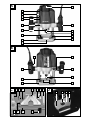
Using the router tool
Press and hold the spindle lock key
10
.
Release the union nut
3
with the open-ended
spanner
27
by turning it anticlockwise.
Release the spindle-lock key
10
.
Then use the router tool. This must be inserted
at least 20 mm (shaft length).
Tighten the union nut
3
firmly with the open-
ended spanner
27
.
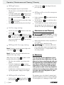
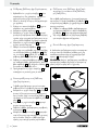
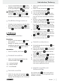
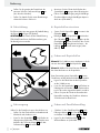
Attaching the extractor adapter
Put the extractor adapter
21
on the drilling ex-
tractor
18
provided.
Screw together the extractor’s screws
22
and
the under side of the base plate
7
.
Connect a vacuum device approved for the
extraction of sawdust and splinters to the ex-
tractor
21
(see Fig. G).
Reducer
Connecting:
Slide the reducer
28
in to the suction adapter
21
.
Slide the hose for an approved dust extraction
unit (e.g. a workshop vacuum) onto the reduc-
er
28
.
Removal:
Pull the hose of the vacuum unit off of the re-
ducer
28
.
Pull off the reducer
28
.
Changing the collet
Note: All router bits of the router sets have a 8 mm
shaft.
Start with the already installed collet 8 mm
4
.
Change the collet for a router bit with a 6 mm shaft
as described below.
Release the union nut by turning it anticlock-
wise using the open-ended spanner
27
until
the collet 8 mm
4
is removed.
Insert the collet 6 mm
23
.
ATTENTION! Tighten the union nut
3
firmly
with the open-ended spanner
27
once the rout-
er bit
17
is inserted. Otherwise the collet might
be damaged.
Fitting the guide fence
Unscrew the both of the sliding bar’s
29
screws with a Philips screw driver.
Secure the sliding bar
29
to the rip fence
24
and tighten the screws.
Operation
Switching on and off
Switching on:
Press and hold the start lockout
20
.
Activate the ON / OFF switch
19
. Once the
machine has started, release the start lockout
20
.

11 GB/CY
Operation
Switching off:
Release the ON / OFF switch
19
.
Presetting the speed
Set the desired speed using the speed setting
wheel
1
.
1–2 = low speed
3–4 = middle speed
5–7 = high speed
Set the milling depth
1.
Ensure that the clamping lever
16
is locked down
.
If it is loose turn it anti-clockwise until it is locked.
2. P
lace the device on the work piece to be wo
rked
upon.
3. Turn the step stop
9
until it locks into the lowest
position.
4. Loosen the lock screw
11
.
5. Loosen the clamping lever
16
by turning it
clockwise and pushing the device down until the
route bit touches the surface of the work-piece.
6. Lock the clamping lever in place
16
by turning
it anti-clockwise.
7. Push the depth stop
12
down until it reaches
the lowest position of the step stop
9
. Move
the index indicator
13
to the position “0“ on
the dial milling depth adjustment
14
.
8. Adjust the depth stop
12
to the desired depth,
tighten the lock screw
11
. Afterwards the index
indicator
13
should no longer be adjustable.
9. Loosen the clamping lever
16
and and lead the
device back up.
Readjust the Milling depth
The milling depth can be adjusted with the con-
trol dial
15
.
Loosen the clamping lever
16
by turning it
clockwise and pushing the device down until
the depth stop
12
touches the step stop
9
.
Lock the clamping lever in place
16
by turning
it anti-clockwise.
Set the milling depth with the control dial
15
.
Loosen the clamping lever
16
by turning it
clockwise and lead the device back up. Check
the milling depth through a further practical test.
Set the milling depth with the
step stop
You can use the step stop
9
with deeper depths in
several steps with less takeoff.
Set the desired milling depth with the lowest
step of the step stop
9
(as described above).
Then set it at higher level for the first attempt.
Milling direction
The milling process must always go against the
rotationary direction on the router bit
17
(Counter
rotation).
ATTENTION: When milling in the direction of the
router bit (counter rotation) the device fly out of
your hand.
Start-up / Operation

12 GB/CY
Warranty / Disposal
Operation / Maintenance and Cleaning / Warranty
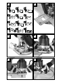
Milling Process
Set the milling depth as previously described.
Place the device on the desired work-piece and
switch it on.
Loosen the clamping lever
16
by turning it clock-
wise and pushing the device down until it touches
the surface of the depth stop
12
on the step
stop
9
.
Lock the device into place by turning the clamp
lever
16
anti-clockwise.
Mill with even speed and even pressure (see fig. I).
Set the copy casing
Set the copy casing
26
from below on the slid-
ing bar
8
.
Secure the copy casing
26
with the two screws
22
of the extractor adapter on the base plate
7
.
Ensure that the copy casing
26
is set the right
way round - the thrust ring
25
must be pointing
down (see fig. D).
Milling with the copy casing
Note! The pattern must be at least as high as the
copy casing’s
26
thrust ring
25
.
Note! Chose the router bit as small as the inner
diameter of the copy casing.
When using a copy casing
26
the pattern can be
transferred onto the work piece.
Place the router with the copy casing on the
pattern.
Loosen the clamping lever
16
by turning it
clockwise and lower the device until it reaches
predetermined depth.
Lead the device with the protecting copy cas-
ing along the pattern. Apply pressure lightly.
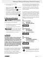
Milling with a rip fence
Push the rip fence
24
along the guide rail
6
of
the base plate
7
and tighten the screws
5
.
Put the rip fence
24
on the edge of the work
piece (see fig. F, H).
Milling with a circular compass
(see fig. J)
Put the centring pin
30
in the marked mid point
of the circle.
Turn the rip fence
24
over, i.e.the fence side is
facing upwards.
Screw together the centre pin and the rip fence
with a wing bolt. Lock the centre pin to the s
crews
with the slot of the open-ended spanner
27
.
Maintenance and Cleaning
RISK OF INJURY! Switch the
device off and pull the plug out of the mains socket
before carrying out any work on the device.
Always keep the device clean, dry and free of
oil or grease.
Use a dry cloth to clean the housing.
If the connection cable needs
to be replaced, this repair must be performed
by the manufacturer or a representative to pre-
vent safety hazards.
Warranty
The warranty for this appliance is for 3
years from the date of purchase. The ap-
pliance has been manufactured with care
and meticulously examined before deliv-
ery. Please retain your receipt as proof
of purchase. In the event of a warranty
claim, please make contact by telephone
with our Service Department. Only in this
way can a post-free despatch for your
goods be assured.
The warranty covers only claims for material and
maufacturing defects, but not for transport damage,
for wearing parts or for damage to fragile compo-

13 GB/CY
Warranty / Disposal
Operation / Maintenance and Cleaning / Warranty
nents, e.g. buttons or batteries. This product is for pri-
vate use only and is not intended for commercial use.
The warranty is void in the case of abusive and im-
proper handling, use of force and internal tampering
not carried out by our authorized service branch. Your
statutory rights are not restricted in any way by this
warranty.
The warranty period will not be extended by repairs
made unter warranty. This applies also to replaced
and repaired parts. Any damage and defects extant
on purchase must be reported immediately after
unpacking the appliance, at the latest, two days after
the purchase date. Repairs made after the expiration
of the warranty period are subject to payment.
GB
Service Great Britain
Tel.: 0871 5000 720
(0,10 GBP/Min.)
e-mail: k[email protected]
IAN 90981
CY
Service Cyprus
Tel.: 8009 4409
e-mail: kom[email protected]
IAN 90981
Disposal
The packaging is wholly composed of
environmentally-friendly materials that can
be disposed of at a local recycling centre.
Do not dispose of electrical power
tools with the household rubbish!
In
accordance with European Directive 2002 / 96 / EC,
worn out electrical power tools must be collected
separately and taken for environmentally compatible
recycling.
Contact your local refuse disposal authority for more
details of how to dispose of your worn-out devices.

14 GB/CY
Declaration of conformity / Manufacturer
Declaration of conformity /
Manufacturer
We, KOMPERNASS HANDELS GMBH, the person
responsible for documents: Mr Semi Uguzlu, BURG-
STRASSE 21, 44867 BOCHUM, GERMANY, hereby
declare that this product complies with the following
standards, normative documents and EU directives:
Machinery Directive
(2006 / 42 / EC)
EU Low Voltage Directive
(2006 / 95 / EC)
Electromagnetic Compatibility
(2004 / 108 / EC)
RoHS Directive
(2011 / 65 / EU)
Applicable harmonized standards
EN 60745-1:2009+A11
EN 60745-2-17:2010
EN 55014-1:2006+A1+A2
EN 55014-2:1997+A1+A2
EN 61000-3-2:2006+A1+A2
EN 61000-3-3:2008
Type / Device description:
Router POF 1200 A1
Date of manufacture (DOM): 08–2013
Serial number: IAN 90981
Bochum, 31.08.2013
Semi Uguzlu
- Quality Manager -
We reserve the right to make technical modifica-
tions in the course of further development.
Πίνακας περιεχομένων

15 GR/CY
Declaration of conformity / Manufacturer
Εισαγωγή
Χρήση σύμφωνα με τις προδιαγραφές ..........................................................................................Σελίδα 16
Εξοπλισμός ......................................................................................................................................Σελίδα 16
Περιεχόμενα παράδοσης ................................................................................................................Σελίδα 16
Τεχνικά χαρακτηριστικά ...................................................................................................................Σελίδα 17
Γενικέ υποδείξει ασφάλεια για ηλεκτρικά εργαλεία
1. Θέση εργασίας-ασφάλεια ...........................................................................................................Σελίδα 17
2. Ηλεκτρική ασφάλεια ....................................................................................................................Σελίδα 18
3. Ασφάλεια ατόμων ........................................................................................................................Σελίδα 18
4. Ασφαλής λειτουργία και χρήση ηλεκτρονικών συσκευών.........................................................Σελίδα 19
5. Σέρβις ..........................................................................................................................................Σελίδα 19
Ειδικές για τη συσκευή υποδείξεις ασφαλείας για το φρεζάρισμα ..............................................Σελίδα 19
Συμπληρωματικές οδηγίες ...............................................................................................................Σελίδα 20
Αυθεντικός πρόσθετος εξοπλισμός / πρόσθετες συσκευές .........................................................Σελίδα 20
Θέση σε λειτουργία
Σετ φρεζαρίσματος / περιοχές εφαρμογής .................................................................................... Σελίδα 20
Τοποθέτηση εργαλείου φρεζαρίσματος .........................................................................................Σελίδα 20
Σύνδεση προσαρμογέα αναρρόφησης .........................................................................................Σελίδα 21
Εξάρτημα συστολής ........................................................................................................................Σελίδα 21
Αντικατάσταση λαβίδας σύσφιξης .................................................................................................Σελίδα 21
Συναρμολόγηση παράλληλου αναστολέα ....................................................................................Σελίδα 21
Χειρισό
Ενεργοποίηση και απενεργοποίηση ...............................................................................................Σελίδα 21
Προεπιλογή αριθμού στροφών ......................................................................................................Σελίδα 21
Ρύθμιση βάθους φρεζαρίσματος ...................................................................................................Σελίδα 22
Επαναρύθμιση του βάθους φρεζαρίσματος .................................................................................Σελίδα 22
Ρύθμιση του βάθους φρεζαρίσματος με αναστολέα βάθους με βαθμίδες .................................Σελίδα 22
Κατεύθυνση φρεζαρίσματος ...........................................................................................................Σελίδα 22
Διαδικασία φρεζαρίσματος ............................................................................................................Σελίδα 23
Τοποθέτηση χιτωνίου αντιγραφής ..................................................................................................Σελίδα 23
Φρεζάρισμα με χιτώνιο αντιγραφής ...............................................................................................Σελίδα 23
Φρεζάρισμα με παράλληλο αναστολέα ......................................................................................... Σελίδα 23
Φρεζάρισμα με διαβήτη ..................................................................................................................Σελίδα 23
Συντήρηση και καθαρισό .........................................................................................Σελίδα 23
Εγγύηση ........................................................................................................................................Σελίδα 24
Απόσυρση ...................................................................................................................................Σελίδα 24
ήλωση συόρφωση / Kατασκευαστή ......................................................... Σελίδα 25
Πίνακας περιεχομένων

16 GR/CY
Eισαγωγή / Γενικές υποδείξεις ασφάλειας για ηλεκτρικά εργαλεία
Eισαγωγή
Καθετη φρεζα POF 1200 A1
Q
Εισαγωγή
Σας συγχαίρουμε για την αγορά της νέας σας
συσκευής. Επιλέξατε ένα προϊόν υψηλών προδια-
γραφών. Οι οδηγίες χρήσης είναι μέρος αυτού του
προϊόντος. Περιέχουν σημαντικές πληροφορίες
σχετικά με την ασφάλεια, το χειρισμό και την απόρριψη
.
Πριν τη χρήση του προϊόντος εξοικειωθείτε με όλες
τις οδηγίες χρήσης και ασφαλείας. Χρησιμοποιείτε
το προϊόν μόνο με τον τρόπο που περιγράφεται
και για τον τομέα εφαρμογής που αναφέρεται. Σε
περίπτωση μεταβίβασης του προϊόντος σε τρίτους
παραδώστε μαζί και όλα τα έγγραφα.
Χρήση σύφωνα ε τι
προδιαγραφέ
Η συσκευή προορίζεται σταθερά στερεωμένη να
φρεζάρει αυλακώσεις, ακμές, προφίλ και επιμήκεις
οπές σε ξύλο, πλαστικό και ελαφρά υλικά, καθώς
και να φρεζάρει με αντιγραφή. Η συσκευή δεν προ-
ορίζεται για χρήση σε εξωτερικό χώρο. Οποιαδή-
ποτε άλλη χρήση ή τροποποίηση του μηχανήματος
θεωρείται ως αντικανονική και εγκυμονεί σοβαρούς
κινδύνους ατυχημάτων. Αντενδείκνυται η επαγγελ-
ματική χρήση.
Εξοπλισό
Μπροστινή όψη Εικόνα A
1
Προεπιλογή αριθμού στροφών
2
Χειρολαβή
3
Παξιμάδι ρακόρ
4
Λαβίδα σύσφιξης 8 mm (προτοποθετημένη σε
παξιμάδι ρακόρ
3
)
5
Βίδα στερέωσης
6
Ράγα οδηγός
7
Πλάκα έδρασης
8
Πλάκα ολίσθησης
9
Αναστολέας βάθους με βαθμίδες
10
Κουμπί ασφάλισης ατράκτου
11
Βίδα ασφάλισης
12
Αναστολέας βάθους
13
Ενδείκτης
14
Κλίμακα ρύθμισης βάθους φρεζαρίσματος
15
Ρυθμιστής στροφών (ρύθμιση ακριβείας βά-
θους φρεζαρίσματος)
Πίσω όψη Εικόνα B
16
Μοχλός σύσφιξης
17
Εργαλείο φρεζαρίσματος
18
Οπές προσαρμογέα αναρρόφησης
19
Διακόπτης ΟΝ / ΟFF
20
Διάταξη ασφάλισης ενεργοποίησης
Πρόσθετο εξοπλισό Εικόνα C
21
Προσαρμογέας αναρρόφησης
22
Βίδα
23
Λαβίδα σύσφιξης 6 mm
24
Παράλληλος αναστολέας
25
Δακτύλιος εδράνου κύλισης
26
Χιτώνιο αντιγραφής
27
Ανοικτό κλειδί με επιμήκη οπή
28
Εξάρτημα μείωσης
29
Ράβδος ολίσθησης με βίδα για τον παράλληλο
αναστολέα
24
30
Άξονας κεντραρίσματος
31
Κλειδί Άλεν
Σετ φρεζαρίσατο Εικόνα D
32
Φρέζα στρογγύλευσης / με σταθερό προφίλ
24,7 mm
33
Φρέζα στρογγύλευσης / με σταθερό προφίλ
28,6 mm
34
Φρέζα στρογγύλευσης / με σταθερό προφίλ
28,6 mm (R–4)
35
Φρέζα κοίλης αυλάκωσης 12 mm
36
Φρέζα κοίλης αυλάκωσης 24,7 mm
37
Φρέζα αυλάκωσης σχήματος V 9,5 mm
38
Φρέζα αυλάκωσης σχήματος 16 mm
39
Φρέζα κοπής απολήξεων οδόντων 32 mm
40
Φρέζα με όδοντες 14,3 mm
41
Επίπεδη φρέζα 12,7 mm
42
Φρέζα αυλακώσεων 6 mm
43
Φρέζα αυλακώσεων 12 mm
Περιεχόενα παράδοση
1 Καθετη φρεζα
1 Ανοικτό κλειδί με επιμήκη κοπή

17 GR/CY
1 Λαβίδα σύσφιξης 6 mm
1 Λαβίδα σύσφιξης 8 mm (τοποθετημένη)
1 Προσαρμογέας αναρρόφησης
1 Παράλληλος αναστολέας
1 Χιτώνιο αντιγραφής
1 Άξονας κεντραρίσματος
1 Σετ φρέζας 12 τεμαχίων (με κλειδί Άλεν)
1 Εξάρτημα συστολής
1 Κλειδί Άλεν
1 Οδηγίες χρήσης
Τεχνικά χαρακτηριστικά
Ονομαστική ισχύς: 1200 W
Ονομαστική τάση: 230 V∼, 50 Hz
Αριθμός στροφών ρελαντί:
n
0
11000–30000 min
–1
Διαδρομή κάτω μέρους
φρέζας: 55 mm
Υποδοχή εργαλείου: 6 / 8 mm
Κλάση προστασίας: II /
Πληροφορίε θορύβου και κραδασών:
Τιμή μέτρησης για θόρυβο εξακριβωμένη σύμφωνα
με EN 60745. Η αξιολογημένη με Α στάθμη ηχητικ
ής
πίεσης του ηλεκτρικού εργαλείου ανέρχεται τυπικά σε:
Στάθμη ηχητικής πίεσης: 84,7 dB(A)
Στάθμη ηχητικής ισχύος: 95,7 dB(A)
Αβεβαιότητα μέτρησης K: 3 dB
Φοράτε ωτασπίδε!
Αξιολογηένη επιτάχυνση, τυπικά:
Κραδασμοί στο χέρι / βραχίονα a
h
= 6,437 m / s²
Αβεβαιότητα μέτρησης K = 1,5 m / s²
Η αναφερόμενη στις
παρούσες οδηγίες στάθμη δονήσεων μετρήθηκε με
τυποποιημένη μέθοδο μέτρησης σύμφωνα με το
πρότυπο EN 60745 και μπορεί να χρησιμοποιηθεί
για τη σύγκριση της συσκευής. Η δεδομένη τιμή
εκπομπής δονήσεων μπορεί επίσης να χρησιμοποιηθ
εί
σε μια εισαγωγική εκτίμηση της έκθεσης.
Η στάθμη δονήσεων μεταβάλλεται ανάλογα με τη
χρήση του ηλεκτρικού εργαλείου και σε μερικές
περιπτώσεις ενδέχεται να υπερβαίνει την τιμή που
αναφέρεται στις παρούσες οδηγίες. Η επιβάρυνση
δονήσεων ενδέχεται να υποτιμηθεί, σε περίπτωση
που το ηλεκτρικό εργαλείο χρησιμοποιείται τακτικά
με τέτοιο τρόπο.
Υπόδειξη: Για τον ακριβή υπολογισμό της επιβά-
ρυνσης κραδασμών κατά τη διάρκεια ενός ορισμέ-
νου χρονικού διαστήματος εργασίας θα πρέπει να
ληφθούν υπόψη και οι χρόνοι κατά τους οποίους
η συσκευή είναι απενεργοποιημένη ή λειτουργεί χω-
ρίς όμως να παράγει πραγματικά έργο. Αυτό μπορεί
να μειώσει σημαντικά την επιβάρυνση κραδασμών για
το συνολικό χρονικό διάστημα εργασίας.
Γενικέ υποδείξει ασφάλεια
για ηλεκτρικά εργαλεία
ιαβάστε όλε τι
υποδείξει ασφάλεια και οδηγίε! Οι πα-
ραβιάσεις κατά την τήρηση των υποδείξεων ασφά-
λειας και των οδηγιών ενδέχεται να προκαλέσουν
ηλεκτροπληξία, πυρκαγιά ή / και σοβαρούς τραυ-
ματισμούς.
ιαφυλαξτε ολε τι υποδειξει ασφαλεια
και τι οδηγιε για ελλοντικη χρηση!
Ο ορος που χρησιμοποιειται στις υποδειξεις ασφα-
λ
ειας «ηλεκτρονικο εργαλειο» αναφερεται σε ηλεκτρικ
α
εργαλεια που λειτουργουν με το δικτυο (με καλωδιο
δικτυου) και σε αυτa που λειτουργουν με μπαταρια
(χωρις καλωδιο δικτυου).
1. Θέση εργασία-ασφάλεια
α) ιατηρείτε το χώρο εργασία σα κα-
θαρό και καλά φωτισένο. Η ακαταστασία
καθώς και ο ελλιπής φωτισμός του χώρου εργα-
σίας μπορεί να οδηγήσει σε ατυχήματα.
β) Μην εργάζεστε ε τη συσκευή σε περι-
βάλλον όπου υφίστα ται κίνδυνο
έκρηξη, στο οποίο υπάρχουν εύφλε-
κτα υγρά, αέρια ή σκόνη. Τα ηλεκτρονικά
εργαλεία παράγουν σπίθες, οι οποίες μπορεί
να αναφλέξουν τη σκόνη ή τους ατμούς.
γ) Κρατήστε τα παιδιά και άλλα άτοα
ακριά από το ηλεκτρο νικό εργαλείο
κατά τη διάρκεια χρήση του. Σε περί-
Eισαγωγή / Γενικές υποδείξεις ασφάλειας για ηλεκτρικά εργαλεία

18 GR/CY
Γενικές υποδείξεις ασφάλειας για ηλεκτρικά εργαλεία
Γενικές υποδείξεις ασφάλειας για ηλεκτρικά εργαλεία
πτωση μη τήρησης ίσως χάσετε τον έλεγχο της
συσκευής.
2. Ηλεκτρική ασφάλεια
α) Το βύσα σύνδεση συσκευή θα πρέ-
πει να ταιριάζει στην πρίζα. Απαγορεύ-
εται η τροποποίηση ε οποιοδήποτε
τρόπο του βύσατο. Απαγορεύεται η
χρήση βύσατο προσαρογέα αζί
ε συσκευέ ε προστατευτική γείωση.
Το ανέπαφο βύσμα και η κατάλληλη πρίζα μει-
ώνουν τον κίνδυνο πρόκλησης ηλεκτροπληξίας.
β) Αποφύγετε τη σωατική επαφή ε
γειωένε επιφάνειε, όπω σωλήνε,
θεραντικά σώατα, εστίε και ψυγεία.
Υφίσταται υψηλός κίνδυνος ηλεκτροπληξίας
όταν το σώμα σας γειωθεί.
γ) Κρατήστε τη συσκευή ακριά από τη
βροχή και την υγρασία. Η εισχώρηση νε
ρού
μέσα σε μία ηλεκτρονική συσκευή αυξάνει τον
κίνδυνο ηλεκτροπληξίας.
δ) Μην χρησιοποιείτε το καλώδιο για
άλλο λόγο, για να εταφέρετε τη συ-
σκευή, για να την αναρτήσετε ή για να
τραβήξετε το βύσα από την πρίζα.
Κρατήστε το καλώδιο ακριά από θερ-
ότητα, λάδι, αιχηρέ ακέ ή κινούε-
να εξαρτήατα συσκευή. Κατεστραμμένο
ή τυλιγμένο καλώδιο αυξάνει τον κίνδυνο πρό-
κλησης ηλεκτροπληξίας.
ε) Για χρήση ηλεκτρονική συσκευή σε
εξωτερικού χώρου, χρησιοποιήστε
όνο καλώδιο επέκταση που είναι
κατάλληλο για εξωτερική χρήση. Η
χρήση ενός καλωδίου κατάλληλο για εξωτερική
χρήση μειώνει τον κίνδυνο ηλεκτροπληξίας.
ζ) Σε περίπτωση που είναι αναπόφευκτη
η λειτουργία του ηλεκτρικού εργαλείου
σε υγρό περιβάλλον, χρησιοποιείτε
προστατευτικό διακόπτη συνολικού
ρεύατο προ το σφάλα. Η χρήση
προστατευτικού διακόπτη συνολικού ρεύματος
προς το σφάλμα μειώνει τον κίνδυνο ηλεκτρο-
πληξίας.
3. Ασφάλεια ατόων
α) Επιδείξτε εγάλη προσοχή, έχετε πάντο-
τε επίγνωση των πράξεών σα και δείξ-
τε ιδιαίτερη συναίνεση στην εργασία
που πραγατοποιείτε ε το ηλεκτρονι-
κό εργαλείο. Μην χρησιοποιείτε τη
συσκευή όταν δεν
είσαστε συγκεντρω-
ένοι ή όταν
νοιώθετε κούραση ή ενώ
βρίσκεστε υπό
την επήρεια ναρκωτικών,
αλκοόλ ή φαράκων. Ακόμα και μόλις μία
στιγμή
αφηρημάδας κατά τη χρήση της συσκευής
μπορεί να οδηγήσει σε σοβαρούς τραυματι
σμούς.
β) Φοράτε προσωπικό προστατευτικό εξο-
πλισό και πάντα προστατευτικά γυα-
λιά. Ο προσωπικός προστατευτικός εξοπλισμός
όπως είναι αναπνευστική μάσκα, προστατευτικά
παπούτσια που δεν γλιστράνε, προστατευτικό
κράνος ή ωτοασπίδες, ανάλογα με το είδος και
την εφαρμογή του μειώνουν τον κίνδυνο πρό-
κλησης τραυματισμών.
γ) Αποφεύγετε την αθέλητη θέση σε λει-
τουργία. Βεβαιωθείτε ότι το ηλεκτρικό
εργαλείο είναι απενεργοποιηένο προ-
τού το συνδέσετε στην ηλεκτρική τρο-
φοδοσία ή το πάρετε και το εταφέρετε.
Εάν κατά τη μεταφορά της συσκευής έχετε το
δάκτυλό σας στο διακόπτη ΕΝΤΟΣ / ΕΚΤΟΣ ή
η συσκευή είναι ενεργοπ οιημένη, ενδέχεται να
προκληθούν ατυχήματα.
δ) Αποακρύνετε τα εργαλεία ρύθιση ή
τα κλειδιά προτού ενεργοποιήσετε τη
συσκευή. Ενα εργαλείο ή ένα κλειδί που βρί-
σκεται πάνω σε ένα περιστρεφόμενο εξάρτημα
συσκευής μπορεί να προκαλέσει τραυματισμούς.
ε) Αποφεύγετε αντικανονική στάση του
σώατό σα. Φροντίζετε ώστε να
υπάρχει πάντα σταθερή θέση και δια-
τηρείτε ανά πάση στιγή την ισορροπία
σα. Ετσι μπορείτε να ελέγχετε καλύτερα τη συ-
σκευή και ιδιαίτερα σε απρόσμενες καταστάσεις.
ζ) Φοράτε κατάλληλο ρουχισό. Μην
φοράτε φαρδιά ρούχα και κοσήατα.
Κρατήστε τα αλλιά, το ρουχισό και
τα γάντια ακριά από τα κινούενα
εξαρτήατα. Ο φαρδύς ρουχισμός που δεν
έχει στενή εφαρμογή, τα κοσμήματα ή τα μαλλιά
μπορεί να πιαστούν από τα κινούμενα εξαρτήματα.

19 GR/CY
Γενικές υποδείξεις ασφάλειας για ηλεκτρικά εργαλεία
η) Κατά τη συναρολόγηση διατάξεων
αναρρόφηση και συλλογή, φροντί
στε ώστε αυτέ να έχουν συνδεθεί και
να χρησιοποιούνται σωστά. Η χρήση
τέτοιου είδους διατάξεων μειώνει τον κίνδυνο
από τη σκόνη.
4. Ασφαλή λειτουργία και χρήση
ηλεκτρονικών συσκευών
α) Μην υπερφορτώνετε τη συσκευή. Χρη-
σιοποιήστε το ηλεκτρονικό εργαλείο
που είναι κατάλληλο για την εργασία
σα. Με το κατάλληλο ηλεκτρονικό εργαλείο
μπορείτε να εργαστείτε καλύτερα και με μεγαλύ-
τερη ασφάλεια εντός του καθορισμένου τομέα
απόδοσης.
β) Μην χρησιοποιείτε ηλεκτρονικό
εργαλείο, του οποίου ο διακόπτη
είναι ελαττωατικό. Ενα ηλεκτρονικό
εργαλείο που δεν μπορεί να ενεργοποιηθεί ή να
απενεργοποιηθεί είναι επικίνδυνο και θα πρέπει
να επιδιορθωθεί.
γ)
Πριν προβείτε σε ρυθίσει τη ηχανή
,
σε αντικατάσταση εξαρτηάτων ή σε
απόθεση τη ηχανή, αποσυνδέετε το
βύσα από την ηλεκτρική πρίζα. Αυτά
τα προστατευτικά μέτρα μειώνουν τον κίνδυνο
αθέμιτης εκκίνησης της συσκευής.
δ) Φυλάξτε τα ηλεκτρονικά εργαλεία που
δεν χρησιοποιείτε ακριά από παιδιά.
Μην επιτρέπετε τη χρήση τη συσκευή
σε άτοα, τα οποία δεν είναι έπιστα ή
τα οποία δεν έχουν διαβάσει τι οδηγίε.
Τα ηλεκτρονικά εργαλεία είναι επικίνδυνα όταν
χρησιμοποιούνται από άπειρα άτομα.
ε) Φροντίστε τη συσκευή ε προσοχή.
Ελέγχετε αν τα κινούενα εξαρτήατα
λειτουργούν άψογα και δεν πλοκά-
ρουν, αν υπάρχουν σπασένα ή κατε-
στραένα εξαρτήατα έτσι ώστε να
επηρεάζεται αρνητικά η λειτουργία
τη
συσκευή. Αναθέστε την επιδιό ρθωση
των ελαττωατικών εξαρτη άτων πριν
από τη χρήση στη συσ κευή. Πολλά
ατυχήματα οφείλονται σε ηλεκτρονικές συσκευές
που δεν έχουν συντηρηθεί σωστά.
ζ) ιατηρήστε τα εργαλεία κοπή αιχηρά
και καθαρά. Τα προσεγμένα εργαλεία κοπής
μπλοκάρουν λιγότερο και κόβουν πιο εύκολα.
η) Χρησιοποιήστε το ηλεκτρονικό εργα-
λείο, το εξάρτηα, τα εργαλεία εφαρ-
ογή κ.τ.λ. σύφωνα ε τι οδηγίε
του και ε τον τρόπο που περιγράφε-
ται για αυτό τον ειδικό τύπο συσκευή.
Λάβετε υπόψη σα τι συνθήκε εργα-
σία και τι δραστηριότητε που πρέπει
να πραγατοποιηθούν. Η χρήση ηλεκτρο-
νικών εργαλείων για εφαρμογή άλλη από αυτή
που προδιαγράφεται μπορεί να οδηγήσει σε
επικίνδυνες καταστάσεις.
5. Σέρβι
α) Αναθέστε την επιδιόρθωση τη συσκευ-
ή σα σε υπηρεσία εξυπηρέτηση πε-
λατών ή σε εξειδικευένο ηλεκτρολόγο
και χρησιοποιήστε όνο αυθεντικά
ανταλλακτικά. Με τον τρόπο αυτό μπορεί
να
διασφαλιστεί το γεγονός ότι διατηρείται το επί-
πεδο ασφάλειας της συσκευής.
Ειδικέ για τη συσκευή
υποδείξει ασφαλεία για
το φρεζάρισα
Πιάνετε το ηλεκτρικό εργαλείο όνο
από τι ονωένε επιφάνειε λαβή,
καθώ η ηχανή φρεζαρίσατο πο-
ρεί να ακουπήσει το καλώδιο δικτύου
τη. Η επαφή με έναν αγωγό που φέρει τάση
μπορεί να θέσει υπό τάση τα μεταλλικά εξαρτή-
ματα της συσκευής και να οδηγήσει σε ηλε-
κτροπληξία.
Στερεώστε και ασφαλίστε το τεάχιο
εργασία έσω πίεση ή κατά άλλο τρό-
πο σε ένα σταθερό υπόστρωα. Αν κρατάτε
το τεμάχιο εργασίας μόνο με το χέρι ή κόντρα
στο σώμα, παραμένει ασταθές, κάτι που μπορεί
να οδηγήσει σε απώλεια ελέγχου.
Γενικές υποδείξεις ασφάλειας για ηλεκτρικά εργαλεία

20 GR/CY
Συπληρωατικέ οδηγίε
Ο επιτρεπτό αριθό στροφών των
εργαλείων φρεζαρίσατο πρέπει να
είναι τουλάχιστον ίσο ε το έγιστο
α
ριθό στροφών που αναγράφεται στ
ο
ηλεκτρικό εργαλείο. Ο πρόσθετος εξοπλι-
σμός, που περιστρέφεται γρηγορότερα από το
επιτρεπόμενο, μπορεί να καταστραφεί.
Η ηχανή φρεζαρίσατο ή ο άλλο
πρόσθετο εξοπλισό πρέπει να ται-
ριάζουν ακριβώ στη λαβίδα σύσφιξη
(διάετρο κορού 6 / 8 mm) του ηλε-
κτρικού εργαλείου σα. Τα εργαλεία φρε-
ζαρίσματος, τα οποία δεν ταιριάζουν ακριβώς
στη λαβίδα σύσφιξης του ηλεκτρικού εργαλείου
σας, περιστρέφονται ανομοιόμορφα, δονούνται
πολύ και μπορούν να οδηγήσουν σε απώλεια
του ελέγχου.
Οδηγείτε το ηλεκτρικό εργαλείο στο τε-
άχιο εργασία όνο όταν είναι ενερ-
γοποιηένο. Διαφορετικά υφίσταται κίνδυνος
ανάκρουσης, όταν το εργαλείο τοποθέτησης
αγκιστρώνεται στο τεμάχιο εργασίας.
Μην τοποθετείτε τα χέρια σα στην πε-
ριοχή φρεζαρίσατο και στη ηχανή
φρεζαρίσατο. Με το δεύτερό σα χέρι
κρατάτε την πρόσθετη λαβή ή το περί-
βληα οτέρ. Όταν κρατάτε τη μηχανή φρε-
ζαρίσματος και με τα δυο σας χέρια, τα χέρια
σας δεν είναι δυνατό να τραυματιστούν από τη
μηχανή φρεζαρίσματος.
Ποτέ ην φρεζάρετε εταλλικά αντικείε-
να, καρφιά ή βίδε. Η μηχανή φρεζαρίσμα-
τος
μπορεί να υποστεί βλάβη και να προκληθού
ν
πολύ έντονοι κραδασμοί.
Χρησιοποιήστε κατάλληλε συσκευέ
αναζήτηση, για να εντοπίσετε κρυφά
καλώδια τροφοδοσία ή συβουλευτεί-
τε την τοπική εταιρεία ηλεκτροδότηση.
Η επαφή με ηλεκτρικά καλώδια μπορεί να οδη-
γήσει σε πυρκαγιά ή ηλεκτροπληξία. Η πρόκλη-
ση βλάβης σε έναν αγωγό αερίου μπορεί να
οδηγήσει σε έκρηξη. Η εισροή σε έναν αγωγό
νερού μπορεί να προκαλέσει υλικές ζημίες.
Αυθεντικό πρόσθετο εξοπλι-
σό / πρόσθετε συσκευέ
Χρησιοποιείτε όνο πρόσθετο εξο-
πλισό και συσκευέ, οι οποίε αναφέ-
ρονται στο εγχειρίδιο λειτουργία ή η
υποδοχή των οποίων είναι συβατή ε
τη συσκευή.
Θέση σε λειτουργία
Σετ φρεζαρίσατο / περιοχέ
εφαρογή
Οι αυθεντικέ πρόσθετε συσκευέ περι-
λαβάνονται στα παραδοτέα:
Για την κοπή προφίλ:
32
Φρέζα στρογγύλευσης / με σταθερό προφίλ,
24,7 mm
33
Φρέζα στρογγύλευσης / με σταθερό προφίλ,
28,6 mm
34
Φρέζα στρογγύλευσης / με σταθερό προφίλ,
28,6 mm (R–4)
35
Φρέζα κοίλης αυλάκωσης, 12 mm
36
Φρέζα κοίλης αυλάκωσης, 24,7 mm
37
Φρέζα αυλάκωσης σχήματος V, 9,5 mm
38
Φρέζα αυλάκωσης σχήματος V, 16 mm
39
Φρέζα κοπής απολήξεων οδόντων, 32 mm
Για τη σύνδεση:
40
Φρέζα με όδοντες, 14,3 mm
41
Επίπεδη φρέζα, 12,7 mm
42
Φρέζα αυλακώσεων, 6 mm
43
Φρέζα αυλακώσεων, 12 mm
Υπόδειξη: Εάν ο ένσφαιρος τριβέας μιας μηχαν
ής
φρεζαρίσματος έχει χαλαρώσει, σφίξτε τον με το
κλειδί Άλεν που περιλαμβάνεται στο σετ μηχανής
φρεζαρίσματος.
Τοποθέτηση εργαλείου
φρεζαρίσατο
Πατήστε το κουμπί ασφάλισης ατράκτου
10
και
κρατήστε το πατημένο.
Θέση σε λειτουργία / Χειρισμός
Γενικές υποδείξεις ασφάλειας για ηλεκτρικά εργαλεία / Θέση σε λειτουργία
Seite wird geladen ...
Seite wird geladen ...
Seite wird geladen ...
Seite wird geladen ...
Seite wird geladen ...
Seite wird geladen ...
Seite wird geladen ...
Seite wird geladen ...
Seite wird geladen ...
Seite wird geladen ...
Seite wird geladen ...
Seite wird geladen ...
Seite wird geladen ...
Seite wird geladen ...
Seite wird geladen ...
Seite wird geladen ...
Seite wird geladen ...
-
 1
1
-
 2
2
-
 3
3
-
 4
4
-
 5
5
-
 6
6
-
 7
7
-
 8
8
-
 9
9
-
 10
10
-
 11
11
-
 12
12
-
 13
13
-
 14
14
-
 15
15
-
 16
16
-
 17
17
-
 18
18
-
 19
19
-
 20
20
-
 21
21
-
 22
22
-
 23
23
-
 24
24
-
 25
25
-
 26
26
-
 27
27
-
 28
28
-
 29
29
-
 30
30
-
 31
31
-
 32
32
-
 33
33
-
 34
34
-
 35
35
-
 36
36
-
 37
37


Parkside 1200 A1 Operation and Safety Notes
- Typ
- Operation and Safety Notes
in anderen Sprachen
- English: Parkside 1200 A1
Verwandte Artikel
-
Parkside POF 1200 C2 Translation Of The Original Instructions
-
Kompernass POF1300 Benutzerhandbuch
-
Parkside POF 1200 A1 Operation and Safety Notes
-
-
Parkside POF 1200 D3 Translation Of The Original Instructions
-
-
-
Parkside PSFS 250 A1 Operation and Safety Notes
-
-
Andere Dokumente
-
Bort BOF-1600N Benutzerhandbuch
-
Bort BOF-2100 Benutzerhandbuch
-
Bosch GOF 2000 CE Bedienungsanleitung
-
Bosch POF 1200 Benutzerhandbuch
-
Bosch POF 1200 AE Benutzerhandbuch
-
Westfalia 87 46 87 Benutzerhandbuch
-
Mafell LO 55 Bedienungsanleitung
-
Dremel 231 SHAPER ROUTER TABLE Bedienungsanleitung
-
-