Nordcap 46710803002-G-F-0 Freezer Unit Benutzerhandbuch
- Typ
- Benutzerhandbuch

Bedienungsanweisung
Tiefkühlaggregat TYP 2 HEG-TK
[Artikel-Nr.: 46710803002-G-F-0]
2022-11

Gebrauchsanleitung
N.º MNS00015 -
MANUAL O5 O7
O8
INHALTSVERZEICHNIS
1 Empfang ........................................................................................................................................................................................................... 3
2 Typenschild ....................................................................................................................................................................................................... 3
3 Montageanleitung .......................................................................................................................................................................................... 3
3.1 Allgemeine Hinweise ................................................................................................................................................................................... 3
3.2 Aufstellung .................................................................................................................................................................................................... 3
3.3 Montage ....................................................................................................................................................................................................... 3
3.4 Auswechseln des Stromzuführungskabels ............................................................................................................................................... 4
3.5 Verbindung von der Türverstärkung ......................................................................................................................................................... 4
3.6 Photozelle ..................................................................................................................................................................................................... 4
4 Gebrauchsanweisung .................................................................................................................................................................................... 5
4.1 Anschalten ................................................................................................................................................................................................... 5
4.2 Mikropozessor IR33 Anleitungen ................................................................................................................................................................ 5
4.3 Abtauen ........................................................................................................................................................................................................ 7
4.4 Reinigung ...................................................................................................................................................................................................... 7
4.5 Instandhaltung ............................................................................................................................................................................................. 7
4.6 Längerer Stillstand ....................................................................................................................................................................................... 7
4.7 Störungen ..................................................................................................................................................................................................... 7
ANMERKUNG DES HERSTELLERS
Wir bedanken uns für Ihre Auswahl. Unsere Geräte erfüllen alle relevanten europäischen Normen und Richtlinien. Wir sind sicher ,
dass indem wir Ihren Erwartungen entgegenkommen, Ihre Bedürfnisse befriedigt werden.
Vielen Dank
2

Gebrauchsanleitung N.º MNS00015.00
1 Empfang
Nach Erhalt der Apparate sollte die Verpackung sorgfältig auf eventuelle Beschädigungen während des Transports
untersucht werden.
Nach Entfernen der Verpackung sollte nachgeprüft werden, ob alle Teile vorhanden sind und ob ihr Zustand und ihre
Merkmale der Bestellung entsprechen.
Die Montage, Instandhaltung sowie alle weiteren Eingriffe sollten von ausgebildeten und dafür zugelassenen Technikern ausgeführt
werden. Falls diese Bedingungen nicht eingehalten werden, kann der Hersteller seine Gewährleistungspflicht nicht einhalten.
Dieses Gerät ist ausschließlich und nur in der vom Hersteller beschrieben Form zu benutzen. Nicht sachgemäßer Gebrauch des
Gerätes kann der Anlage und/oder Personen schaden
Es wird darauf hingewiesen, dass aufgrund ständiger technischer Verbesserungen, ohne vorherige Hinweise, Änderungen der hier
genannten Merkmale auftreten können.
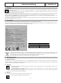
2 Typenschild
Das Typenschild unseren Kühlanlage den Kühlzellen befindet sich aussen seitlich der Schutz.
Dort sind die wichtigsten technischen Daten des Equipments und die Identifizierung des MODELLS und der SERIENNUMMER zu finden.
Letztere sind für irgendwelche Nachfragen beim Hersteller notwendig.
Die Europäische Richtlinie zu Elektro- und Elektronikgeräte-Abfall (WEEE) legt fest, dass am Ende des Nutzungszyklus das
Equipment und alle seine Komponenten, Komponentengruppen und Materialien selektiv eingesammelt werden, um
für die Entsorgung oder die Aufbereitung zur Wiederbenutzung vorbereitet zu werden.
Werfen Sie Equipment mit diesem Symbol nicht in den allgemeinen Müll.
3 Montageanleitung
3.1 Allgemeine Hinweise
Obwohl Aufbau und Funktionstüchtigkeit (wie sie aus dem beigelegten Prüfbericht ersehen können) der Geräte im Werk geprüft
werden, besteht die Möglichkeit der Beschädigung während des Transports. Es wird deshalb empfohlen, nach Erhalt den
allgemeinen Zustand der Geräte zu überprüfen.
3.2 Aufstellung
Vorsichtiges Entfernen der Verpackung und der Palette, um die Oberflächen nicht zu beschädigen. .Ziehen Sie die
Plastikschutzfolie ab.
Es wird empfohlen, das Gerät möglichst weit enfernt von Wärmequellen (wie z. B. Herd, Heizung oder direkte
Sonneneinstrahlung) aufzustellen.
Die Belüftungsschlitze dürfen niemals abgedeckt oder zugestellt werden – Es sollte immer ausreichend Abstand eingehalten
werden, um eine gute Belüftung zu gewährleisten.
3.3 Montage
Bei der Montage müssen immer folgende Normen beachtet werden:
Bauvorschriften und Brandschutzvorschriften.
Legende
a) Spannung (V) b) Frequenz (Hz)
c) Strom (A) d) Leistung (W)
e) Kühlgas (ASHRAE) f) Füllmenge (g)
3

Gebrauchsanleitung N.º MNS00015.00
Unfallverhütungsvorschriften.
Gültige Euronormen.
Das Gerät wird laut Prüfnormen mit Netzstecker und einem genügend langen Stromzuführungskabel geliefert.
Die zu benützende Steckdose sollte leicht zugänglich, für den maximalen Verbrauch (siehe Übersicht Technische Daten)
zugelassen und geerdet sein.
Niemals Steckdosen ohne Erdkabel, Adapter oder Verlängerungen benutzen.
Beim direkten Anschluss ans Netz sollte immer ein den internationalen Normen entsprechender Trennschalter eingebaut werden.
3.4 Auswechseln des Stromzuführungskabels
Wenn das Stromzuführungskabel beschädigt wird, soll dieses durch den Hersteller, seinen Kundendienst oder durch bezeichnete
Personen ersetzt werden, um die Gefahr zu vermeiden.
Stromzuführungskabe
- Typ
- Nennquerschnitt
- Herstellercode
(normal)
(England)
HO5VVF
3 x 1 mm2
43001004
43001001
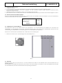
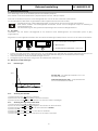
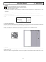
3.5 Verbindung von der Türverstärkung
Alle Kühlzellen mit 800 und 100 Wände haben eine Vorinstallation von der Türverstärkung. Die kühlzellen mit 100 Wände sind
Tiefkühlzellen, und die Kühlzellen mit 80 oder 100 Wände können positiv oder negativ sein. Normalerweise, benutzt man die
Türverstärkung auf Tiefkühlzellen. Die Türverstärkung soll nur auf Tiefkühlzellen einschalten sein.
Wenn Sie auf den Innenseiten der Kühlzelle sind, schalten Sie die Türverstärkung ein:
Stellen Sie das Kabel, das in der Kühlanlage steht, Einsatzteil A (Abb. 1).
Abb. 1
3.6 Photozelle
Wenn Sie die tür offnen, die Licht macht an und den Ventilatormotor haltet an. Diese Befehle sind bei der Photozelle innen der
Kühlzelle gesteuert.
Die Photozelle muss installiert sein. Wenn Sie die Tür öffnen, muss die Photozelle in des lichten Ort sein. Sie installieren die Photozelle
mit den Kabelbinder, die mit der Dokumentation des Apparats geschickt sind.
A
4

Gebrauchsanleitung N.º MNS00015.00
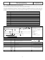
T (ºC)
rd
4 Gebrauchsanweisung
Diese Kühlanlage wurde für die Kühlzellen (Wände der Kühlzellen) konzipiert.
Diese Geräte war für einen Klimabereich 4 (Auentemperatur bis 30ºC, 55% Hr) konzipiert.
Man sollte auf die Kinder aufpassen, damit sichergestellt wird, dass sie mit dem Gerät nicht spielen werden.
Um ein reibungsloses Funktionieren zu gewährleisten sollten folgende Hinweise beachtet werden:
Verstellen Sie nie die vorderen Belüftungsschlitze, um die Leistung des Kompressors nicht einzuschränken.
Keine heißen Getränke oder Nahrungsmittel hineinstellen, da der davon aufsteigende Dampf zur Eisbildung im
Verdampferfach führt.
Die Nichteinhaltung der oben genannten Empfehlungen führt zu höherem Energieverbrauch.
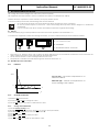
4.1 Anschalten
Sicherstellen, dass der Stecker ordungsgemäß in der Steckdose steckt beziehungsweise der Trennschalter (wenn es gibt)
eingeschaltet ist.
Abgesehen von den folgenden Auskünfte, bitte die Gebrauchsanleitung des Mikroprozessors zu lesen, um das Gerät zu einschalten:
0
I
A – I / 0 – Anschalten / Ausschalten
B – BELEUCHTUNG
C – ELEKTRONISCHE STEUERGERÄT - Thermostat
Danach das Gerät anschalten, indem der Knopf “A” in die Stellung “ON” gebracht wird. Das grüne Lämpchen leuchtet auf und
zeigt die Netzverbindung an. Die Anzeige (display) blinkt einige Sekunden lang, bis sie die Innentemperatur anzeigt.
Der Hauptschalter “B” schaltet die Beleuchtung an und aus.
Die Regulierung der Temperatur erfolgt durch den elektronischen Thermostat “C”.
4.2 Mikropozessor IR33 Anleitungen
4.2.1 Bestimmungen
4.2.2 Änderung des SET POINT
1) Drücken Sie die Taste Set während 5 Sekunde;
2) Benutzen Sie die Tasten def oder aux um den Wert zu ändern;
3) Drucken Sie die Taste Set während 5 Sekunden um den neuen Wert zu bestätigen.
4.2.3 Änderung des Temperatur-Unterschieds
1) Drucken Sie die Tasten Set und Prg während 5s;
2) Durch Sie die Taste aux, der Wert 22 eingeben, dann sind Sie an die Parammeter;
3) Drücken Sie die Taste def oder aux bis Sie den Parammeter rd finden;
4) Drücken Sie Set;
5) Drücken Sie die Taste def oder aux um den Wert zu verhindern;
6) Drücken Sie Set;
7) Drücken Sie die Taste Prg während 5 Sekunden um den Wert zu speichern.
t
St
Set Point (St) – Die minimale temperatur aus ºC für
das Innere des möbels
Temperatur-Unterschied (rd) – Temperaturintervall
aus ºC für den Betrieb des möbels
5

Gebrauchsanleitung N.º MNS00015.00
4.2.4 Konfiguration für HACCP-Kontrolle an den Kontroller IR33
Alle benutzten Mikroprozessoren in unserem Produkten haben HACCP. Oder, der Mikroprozessor hat diese Funktion, oder kann der
Kunde einen HACCP Modul einkaufen, abhängig vom Mikroprozessormodell des Geräts.
Durch seine Programmierung kontroliert der HACCP die Temperatur von gelagerten Produkten. Der HACCP macht eine
automatische Überwachung von der Einheit, bezeichnet und einträgt jede anormale Situation. Wenn es passiert, gibt es ein
Schallsignal. Die erreichte Temperatur und ihre Dauer während des Ereignis sind auf dem Permanent-Speicher (EEPROM)
geschrieben. Der HACCP bezeichnet jede Spannungsausfall während der Zeit wo die gewünschte Temperatur nicht erreicht war.
Bestimmungen von Parammeter
St Set Point
rd Temperatur-Unterschied
AH Höchstniveau der temperatur
AL Unterniveau der temperatur
Ad Verspätung der alarm von höhen und unteren Temperatur
Htd Verspätung der HACCP Alarm
Alarme HA Alarm Überlauf den Wert von AH
Alarme HF Alarm - Spannungsausfall während mehr als 1 Minute und Überfall den Wert von AH
HI Alarm von höhen Temperatur (HI=AH + rd)
LO Alarm von unteren Temperatur (LO=HF - rd)
HAn, HAf Quantität aus Alarmen HA und HF
Anmerkung: Sie befinden diese Parammeter auf dem Mikroprozessor Gebrauchsanleitung
Auf die HACCP Parammeter zu greifen
Auf die HACCP Parameter zu greifen, um sie zu programmieren, müssen Sie die Tasten Set und Prg während
5s zusammendrücken. Es scheint zero. Drücken Sie die Taste aux bis 22 und dann Set. Drücken Sie def oder
aux bis Sie den Parammeter, der Sie programmieren möchten. Drücken Sie Set, den gewünschten Wert zu
programmieren durch die Tasten def oder aux, Drücken Sie Set Sie sind im Parammeter und drücken Sie die
Taste Prg während 5s zu eintragen.
Drücken Sie die Tasten Set und def während 5s die Tasten aux und def oben und unter, um die Details zu
anzeigen.
Drücken Sie die Tasten Set und def während 5s, um die Daten zu löschen. Wenn Sie auf die Parammeter
sind, drücken Sie die Tasten Set, def und aux zusammen bis es “res” erscheint.
Wenn Sie aus dem Menu gehen möchten, müssen Sie die Taste Prg während 5s.
Drücken Sie Prg, um den Schallsignal zu ausschalten.
Datensatz auf den folgenden
Parammeter:
HA, HA1, HA2 e HF, FH1 e HF2
Für jede Parammeter des
Ereignisses, die folgende Werte
eingetragen sind:
y_ Jahr
M_ Monat
d_ Tag
u_ Tag der Woche
h_ Stunde
n_ Minuten
t_ Laufzeit des Ereignises
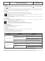
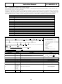
Beispiel zur Konfiguration von HACCP Kontrolle
Parammeter Beispiel Beschreibung Anmerkungen
ST 0 Wert den Stopp des Kompressors
rd 3 (rd+ST) = Wert Start des Kompressors
AH 8 Höchste Temperatur Es ist notwendig zu programmieren
HI 11 (8+3) (AH + rd) Alarm
AL 3 Untere Temperatur Es ist notwendig zu programmieren
LO 0 (3-3) (AL - rd) Alarm
Ad 1 1 Minute Verspätung der Alarme Es ist notwendig zu programmieren
tc
y_ Jahr
u_ Tage der
Woche
M_Monat
h_ Stunde
d_ Tag
n_ Minuten
Datum und Stunde von der Uhr Es ist notwendig zu programmieren
Htd 30 30 min. nach dem Alarmaktivierung, beginnt den Datensatz in HACCP Es ist notwendig zu programmieren
St
rd
6

Gebrauchsanleitung N.º MNS00015.00
4.3 Abtauen
Das Gerät führt automatisch Abtauvorgänge durch. Während dieser Phase leuchtet die Anzeige . Nach dem Abtauen
verlischt diese Anzeige. Darüberhinaus ist es möglich auch zusätzlich manuelle Abtauvorgänge durchzuführen, drücken Sie
die Taste def während 5s.
Es ist ratsam, nach dem Auftauen die Türen geschlossen zu halten, damit die Innentemperatur schnellstmöglich wieder hergestellt
werden kann. Das Abtau- und Kondenswasser sammelt sich auf einem Auffangtablett, das über dem Verdampfer angebracht ist,
so dass es auf diese Weise verdampft. Automatische Verdampfung der Abtauung.
4.4 Reinigung
Zur einwandfreien Hygiene und Konservierung, wird folgende tägliche Reinigung empfohlen:
Häufiges und sorgfältiges Abwischen der Oberflächen mit einem feuchten Tuch.
Dabei kann Wasser und ein neutrales Spülmittel verwendet werden. Zu vermeiden sind chlorhaltige und ätzende
Mittel.
Mit reinem Wasser nachwischen und sorgfältig trocknen.
Es ist ratsam, die Abflusstabletts zu reinigen und das Vorhandensein von Rückständen, die den Abfluß von Kondenswasser
verstopfen können, nachzuprüfen.
4.5 Instandhaltung
Um die Funktionstüchtigkeit des Kühlaggregats über lange Zeit zu erhalten, sollten regelmäßig folgende
Instandhaltungsmaßnahmen am Kondensator durchgeführt werden:
Abschalten und Netzstecker ziehen.
Die Kühleinheit öffnen, der Kondensator ist leicht zugänglich.
Gehen Sie mit dem Staubsauger in Richtung der Rippen über den Kondensator.
Vorsicht mit den Kabeln, nicht daran ziehen. Nicht vergessen, das Fach zu schließen.
4.6 Längerer Stillstand
Bei längeren Zeiten außer Betrieb wird folgendes empfohlen:
Abschalten und Netzstecker ziehen.
Instandhaltungsmaßnahmen durchführen.
4.7 Störungen
Wenn Störungen auftreten, sollten Sie bevor Sie den Kundendienst rufen, erst mal nachprüfen ob:
Der Hauptschalter aufleuchtet.
Das Gerät sich nicht in der Nähe einer Wärmequelle befindet.
Der Kondensator sauber ist und der Ventilator funktioniert.
Nicht zu viel Eis im Verdampfer entstanden ist.
Störung Überprüfen Zu machen
Das Gerät funktionniert nicht
Des Schalters wird man den Stecker
herausziehen Der Schalter anschliessen
Der Schalter wird angeschlossen aber
nicht beleuchtet
Überprüfen, ob den Netzstecker gut angeschlossen
wird
Überprüfen, ob den Netzstecker Strom hat
Der Schalter wird angeschlossen und
beleuchtet Die Parameter des Mikroprozessors überprüfen
Das Gerät erreicht die
Temperatur nicht
Geoffnete Tür Die Tür schliessen
Geschlossene Tür und blockierter
Verdampfer
Ein Auftauen verursachen, um den Verdampfer
sauber wird
Gechlossene Tür und sauberer
Verdampfer
Der Kondensator reinigen
Zu hohe Raumtemperatur
(Sieh Klimaklasse des Geräts)
Wenn diese Kontrollen negativ sind, sollten Sie ausräumen, abschalten und den nächsten Kundendienst rufen.
Hinweis: Die Instandhaltung und Reparatur sollte von technisch ausgebildetem Personal durchgeführt werden. Die Verwendung
von Nicht-Originalersatzteilen befreit den Hersteller von seiner Gewährleistungspflicht und hebt die Garantie auf.
7

Instruction Manual N.º MNS00015 -
MANUAL O5 O7
O8
INDEX
1 Reception ......................................................................................................................................................................................................... 9
2 Rating Plate ...................................................................................................................................................................................................... 9
3 Recommendations for Installation ............................................................................................................................................................... 9
3.1 General Notes .............................................................................................................................................................................................. 9
3.2 Placing .......................................................................................................................................................................................................... 9
3.3 Installation ..................................................................................................................................................................................................... 10
3.4 Replacement of Power Cord .................................................................................................................................................................... 10
3.5 Connection of Door Resistance ................................................................................................................................................................ 10
3.6 Photocell ....................................................................................................................................................................................................... 10
4 Recommendations for the User .................................................................................................................................................................... 11
4.1 Start-up .......................................................................................................................................................................................................... 11
4.2 IR33 Microprocessor Instructions ............................................................................................................................................................... 11
4.3 Defrost ........................................................................................................................................................................................................... 13
4.4 Cleaning ....................................................................................................................................................................................................... 13
4.5 Maintenance ............................................................................................................................................................................................... 13
4.6 Prolonged Inactivity .................................................................................................................................................................................... 13
4.7 Anomalies ..................................................................................................................................................................................................... 13
NOTES
We would like to thank your preference for our equipment, which follow all the European Directives and Standards and will meet
for sure, your expectations and satisfy your needs.
Thank you
8

Instruction Manual N.º MNS00015.00
1 Reception
On receiving the equipment, check carefully that the packaging is intact and has not been damaged in transit.
After unpacking, check that you have all the components and if the characteristics correspond to those on the order
form.
Installation, maintenance and other work should be carried out by specialised and authorised technicians. The
manufacturer accepts no responsibility and will not cover the guarantee if these conditions are not respected.
This appliance must be used according to this manual and only for the manufacturer’s purpose. The incorrect use of the equipment
can cause damages to the equipment and to users.
As a result of our constant effort to make technological improvements, the specifications indicated here are subject to change
without warning.
2 Rating Plate
The rating plate on our cold rooms cooling units is located at the outside lateral of the cover.
It includes the main technical data about the equipment and it identifies the MODEL and SERIAL NO., which are vital pieces of
information for any queries to the manufacturer.
The European directive on Waste from Electrical and Electronic Equipment (WEEE) specifies that, at the end of its life
cycle, the equipment and all of its components, subassemblies and consumable materials should be sent separately
for treatment for it to be destroyed, recycled or reused.
Do not put equipment with this symbol together with unseparated urban waste.
3 Recommendations for Installation
3.1 General Notes
Although the production and operation (as prove the enclosed test report) of each appliance is rigorously controlled during
manufacture, this does not exclude the possibility of damage caused in transit. The general condition of the appliance should
therefore be checked on arrival.
3.2 Placing
Remove the packaging or pallet carefully so that the equipment’s surfaces are not damaged. Remove the PVC
protection.
The appliance should be installed away from heat sources (ex: heating appliances) and direct sunlight.
The air vents should never be covered or blocked - must be guaranteed free space to this areas, assuring a good air
circulation.
Legend
a) Voltage (V) b) Frequency (Hz)
c) Current (A) d) Power (W)
e) Refrigeration gas
(ASHRAE)
f) Gas capacity (g)
9

Instruction Manual N.º MNS00015.00
3.3 Installation
The following standards should always be bared in mind during installation:
Regulations concerning the buildings, and anti-fire standards.
Rules concerning accident prevention.
European standards into effect.
The appliance is supplied with a plug complying test standards, and with a regulation power cord long, enough to allow
connection to the electric socket.
The socket should be easily accessible and the right size for maximum consumption (see identification plate). It must have an
EARTH WIRE.
Never use sockets or plugs without an earth wire, nor should you use adapters or extensions.
For direct connections to the current, a circuit breaker must always be installed. This complies international standards.
3.4 Replacement of Power Cord
If the power cord is damaged, this must be replaced by the manufacturer, by its technical services or by qualified person to avoid
danger.
Power cord:
- Type
- Nominal Section
- Producer Code
(normal)
(Great Britain)
HO5VVF
3 x 1 mm2
43001004
43001001
3.5 Connection of Door Resistance
All the cold rooms with 80 and 100 panels have a preinstallation of door resistance. The cold rooms with 100 panels are freezer cold
rooms, those with 80 and 100 panels can have a positive and negative temperature. Usually, the door resistance is appropriate to
be used in freezer cold rooms and must be connected only in this kind of equipment.
Working on the exterior of the cold room, you must proceed to the connection of the door resistance as follows:
Fix the cord that you can find on the cooling unit, spare part A (Fig. 1).
Fig. 1
3.6 Photocell
Whenever you open the door, the lightning switches on and the motorfan stops. These operations are controlled by a photocell in
the interior of cold rooms.
The photocell is delivered without being installed. This one must be installed in a place where there is the most light when you open
the door. You must install it using the cable ties sent with the machinery documents.
A
10

Instruction Manual N.º MNS00015.00
T (ºC)
rd
4 Recommendations for the User
This cooling unit has been designed for cold rooms (cold room panels).
This equipment has been created to work at a 4 climatic class (30ºC room temperature, 55% Hr).
Children should be supervised to ensure that they do not play with the device.
To ensure that they function well, the following points must be followed:
Do not block the frontal air vent as this will seriously affect the efficiency of the compressor.
Do not use pointed objects to remove ice - that could damage the evaporator and be dangerous to health and
environment.
If you do not follow the above advises, there will be an increase usage electrical energy.
4.1 Start-up
Make sure that the plug is correctly inserted in the socket or that the appliance’s circuit breaker is on.
To connect the equipment, besides the following information, you must consult the microprocessor technical schedule.
0
I
A – I / 0 – Switch ON / OFF
B – LIGHTENING
C – ELECTRONIC DEVICE - Thermostat
Press button “A”, placing it in the “ON” position. The green light will come on and indicate connection. At the same time, the
display will flash for some seconds until it indicates the inner temperature.
The “B” button switches on and off the light inside the cold room.
Temperature is controlled automatically through the electronic thermostat “C”.
4.2 IR33 Microprocessor Instructions
4.2.1 Definitions
4.2.2 SET POINT modification
1) Press the Set for 5 second;
2) Use the key def or aux to change the value;
3) Press the Set key for 5 seconds to confirm the new value.
4.2.3 Change of the Differential
1) Press the Set key and Prg for 5s;
2) Through the aux key, introduce the value 22, you are now in the parameters;
3) Press the def key or aux till you reach the parameter rd;
4) Press Set;
5) Press the key def or aux to modify the value;
6) Press Set;
7) Press the key Prg for 5 seconds to memorise the value.
t
St
Set Point (St) – The lowest temperature in ºC
inside the cabinet.
Differential (rd) – Interval of temperature in ºC
for the working of the cabinet.
11

Instruction Manual N.º MNS00015.00
4.2.4 Configuration for HACCP control on IR33 controllers
All the microprocessors used in our products have HACCP, or the microprocessor possesses this function, or the client can buy a
HACCP module to be used on the equipment.
Through its programming, the HACCP, guarantees the temperature control of stocked products. The HACCP realises an automatic
monitoring of the unity, recording and indicating any abnormal situation. When it happens it produces a warning signal. The
reached temperature during the occurrence, as well as its duration are recorded on the permanent memory (EEPROM). The
HACCP indicates the loss of voltage occurred during the time when it was impossible to maintain the requested temperature.
Parammeters Definition
St Set Point
rd Temperature differential
AH Highest temperature
AL Lowest temperature
Ad Delay of low and high temperature alarm
Htd HACCP Delay alarm
Alarme HA AH value overtaking Alarm
Alarme HF Loss of voltage alarm during more than 1 minute and AH value overtaking
HI High temperature alarm (HI=AH + rd)
LO Low temperature alarm (LO=HF - rd)
HAn, HAf Quantity of HA and HF occurred alarms
Notice: These parameters are defined in the microprocessor manual
How to access the HACCP parameters
To access the HACCP parameters in order to programm it, press the Set and Prg keys at the same time for
5s. It shows zero. Press the aux key till it reaches 22 and the press Set. Press def or aux till you find the
parameter that you would like to programm. Press Set, Insert the requested value through the def or aux
keys, Press Set in order to come back to the parameter and then press the Prg key for 5s to record.
To view the details you must press Set and def for 5s, the aux and def keys up and down.
To delet the recorded information you must press Set and def for 5s. Once you are in the parameters, press
Set, def and aux simultaneously till “res” appears.
Whenever you would like to get out of the menu you must press Prg, for 5s.
To switch off the warning alarm you must press Prg.
The records are made on the
following parameters:
HA, HA1, HA2 e HF, FH1 e HF2
For each parameter the following
values regarding the occurrences
are recorded:
y_ year
M_ month
d_ day
u_ day of the week
h_ hour
n_ minutes
t_ occurrence period of time
HACCP control configuration example
Parameters Example Description Notice
ST 0 Compressor value stop
rd 3 (rd+ST) = compressor start value
AH 8 Allowed highets temperature You must programm
HI 11 (8+3) (AH + rd) Alarm
AL 3 Allowed lowest temperature You must programm
LO 0 (3-3) (AL - rd) Alarm
Ad 1 1 Minute of delay in the alarms You must programm
tc
y_ year
u_ day of
the week
M_month
h_ hours
d_ day
n_ minutes
Date and hour of the clock You must programm
Htd 30 30 min. after the alarm being tripped the HACCP begins to
record You must programm
St
rd
12

Instruction Manual N.º MNS00015.00
4.3 Defrost
The appliance defrosts automatically. Switch goes on according to the defrosting stage. After defrosting the switch goes off
automatically - it is also possible to do manual defrosting (besides the ones already programmed), for so you just have to
press the def key for 5s.
It is advisable not to open the doors after defrosting so that the normal temperature is obtained more rapidly. Our cold rooms have
automatic defrosting.
4.4 Cleaning
To ensure perfect hygiene and conservation, please clean as follows:
Cleaning the surfaces carefully with a damp cloth.
Always when using water and detergent, make sure these are neutral, and avoiding those which are chlorine-based
or abrasive.
Rinsing with clean water and drying carefully.
It is entirely inadvisable to use pressurised jets of water, especially in the direction of the compressor.
4.5 Maintenance
To ensure that the cooling system lasts for a long time and functions correctly, regular maintenance of the condenser should be
carried out. This should be done in the following way:
Switch off the appliance and unplug it.
Open the compressor compartment; the condenser will be easily accessible.
Pass the vacuum cleaner across the condenser in the slat’s direction.
Be careful not to stretch the cables, do not stretch them. Remember to close the compartment.
4.6 Prolonged Inactivity
When long periods of inactivity are foreseen, the following procedure is recommended:
Unplug the appliance.
Carry out maintenance operations.
4.7 Anomalies
If you notice any anomalies or malfunctions, before calling the technical services, check that:
The general switch is on.
The equipment is not near any heat sources.
The condenser is clean and the fan motor is functioning.
There is not too much ice on the evaporator.
Anomaly Verify To do
The equipment does not
work
The switch is off Connect the switch
The switch is connected but is not
lightened
Check if the plug is well inserted
Check if the plug has current
The switch is connected and lightened Check the microprocessor parameters
The equipment does not
reach the temperature
Opened door Close the door
Closed door and blocked evaporator Provoke a defrosting to clean the evaporator
Closed door and cleaned evaporator
Clean the condenser
Room temperature is too high
(see equipment climate class)
If the problem persists, it is recommended that you remove everything from inside the appliance, unplug it, and seek technical
assistance.
Note: Specialised staff must carry out maintenance and the manufacturer declines any responsibility for the use of unauthorised
parts that cancel the guarantee.
13

Finanzen / Service
28307 Bremen
Thalenhorststraße 15
Tel.+49 421 48557-0
Fax+49 421 488650
bremen@nordcap.de
Vertrieb Ost
12681 Berlin
Wolfener Straße 32/34, Haus K
Tel.+49 30 936684-0
Fax+49 30 936684-44
berlin@nordcap.de
Vertrieb West
40699 Erkrath
Max-Planck-Straße 30
Tel.+49 211 540054-0
Fax+49 211 540054-54
erkrath@nordcap.de
Vertrieb Nord
21079 Hamburg
Großmoorbogen 5
Tel.+49 40 766183-0
Fax+49 40 770799
hamburg@nordcap.de
Vertrieb Süd
55218 Ingelheim
Hermann-Bopp-Straße 4
Tel.+49 6132 7101-0
Fax+49 6132 7101-20
ingelheim@nordcap.de
www.nordcap.de
-
 1
1
-
 2
2
-
 3
3
-
 4
4
-
 5
5
-
 6
6
-
 7
7
-
 8
8
-
 9
9
-
 10
10
-
 11
11
-
 12
12
-
 13
13
-
 14
14


