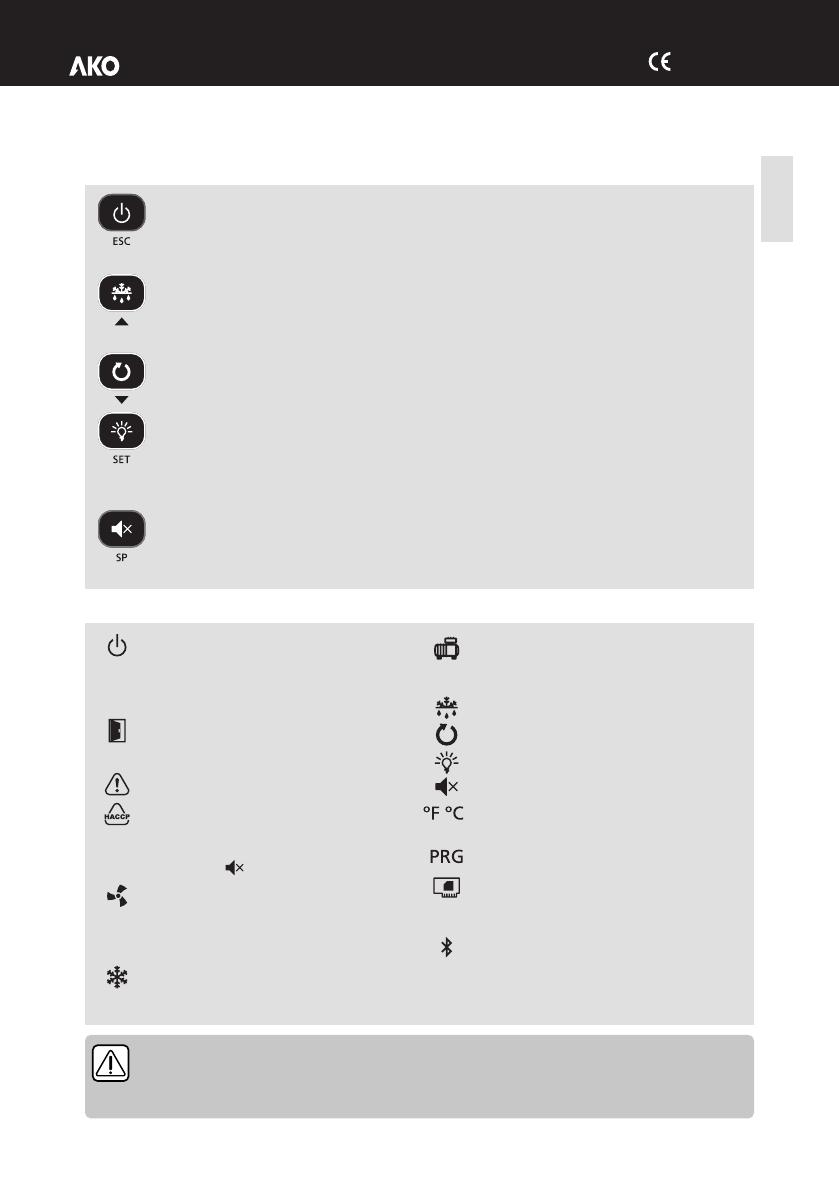
AKO 16523 Benutzerhandbuch

Typ
Benutzerhandbuch
AKO-16523 AKO-16520 AKO-16523D
AKO-16523P AKO-16520P AKO-16523-V
AKO-16523L
Controlador de temperatura para cámara frigorífica
Temperature controller for cold rooms
Contrôleur de température pour chambre froide
Temperatursteuerung für Kühlräume
Controlador de temperatura para câmara frigorífica
Guía rápida / Quick guide / Guide rapide /
Schnellstartanleitung / Guia rápido
es en fr de pt 1652H311 Ed.12
2
Advertencias
-Utilizar el equipo no respetando las instrucciones del fabricante, puede alterar los requisitos de
seguridad del aparato. Para el funcionamiento correcto del mismo sólo deberán utilizarse sondas de las
suministradas por AKO.
2
-Entre –40 ºC y +20 ºC, si se prolonga la sonda NTC hasta 1.000 m con cable de mínimo 0,5 mm , la
desviación máxima será de 0,25 ºC (Cable para prolongación de sondas ref. AKO-15586. Conectar la malla a
tierra sólo en uno de sus extremos).
-Para el funcionamiento correcto del aparato solamente deberán utilizarse sondas del tipo NTC de las suminis-
tradas por AKO.
-Debe ser instalado en un sitio protegido de las vibraciones, del agua y de los gases corrosivos, donde la
temperatura ambiente no supere el valor reflejado en los datos técnicos.
-Para que la lectura sea correcta, la sonda debe ubicarse en un sitio sin influencias térmicas ajenas a la
temperatura que se desea medir o controlar.
-El grado de protección IP65 solo es válido con la tapa protectora cerrada.
-El grado de protección IP65 sólo es válido si la entrada de cables al equipo se realiza mediante tubo para
conducciones eléctricas + prensastopas con IP65 o superior. El tamaño de los prensastopas debe ser el
adecuado para el diametro de tubo utilizado.
-No rociar directamente el equipo con mangueras de alta presión, puede resultar dañado.
IMPORTANTE:
ŸLos relés AUXILIARES son programables, su funcionamiento depende de la configuración.
ŸLa función de las entradas digitales depende de la configuración.
ŸLas intensidades y potencias indicadas son las máximas de trabajo admitidas.
Conexionado
Desconectar siempre la alimentación para realizar el conexionado.
Las sondas y sus cables NUNCA deben instalarse en una conducción junto con cables de potencia, control o
alimentación.
El circuito de alimentación debe estar provisto de un interruptor para su desconexión de mínimo 2 A, 230 V,
situado cerca del aparato. El cable de alimentación será del tipo H05VV-F o NYM 1x16/3. La sección a utilizar
2
dependerá de la normativa local vigente, pero nunca deberá ser inferior a 2.5 mm .
2
Los cables para las salidas de los relés o contactor deben tener una sección de 2.5 mm , deben admitir temperaturas
de trabajo iguales o superiores a 70 ºC y se deben instalar minimizando su flexión.
La zona de conexión a 120 / 230 V~ debe mantenerse despejada de cualquier elemento externo.
El conexionado a realizar depende del tipo de instalación. Utilice el esquema adecuado en funcn
de la opción escogida en el asistente. Consulte las opciones disponibles en la hoja de esquemas
adjunta.
El modelo AKO-16523D dispone de contactor para poder conectar resistencias de desescarche trifásicas,
compresor trifásico o ventiladores trisicos según las necesidades de su instalación, consulte como conectarlo en la
hoja de esquemas adjunta.
Mantenimiento
Limpie la superficie del equipo con un paño suave, agua y jabón.
No utilice detergentes abrasivos, gasolina, alcohol o disolventes, el equipo puede resultar dañado.
1652H311 Ed.12
1652H311 Ed.12
3
Teclado
Indicadores
Pulsando durante 3 segundos, activa / desactiva el modo Stand-By. En este modo la regulación se detiene
y el display muestra el icono m.
En el menú de programación, sale del parámetro sin guardar cambios, retrocede al nivel anterior o sale de
programación.
Una pulsación corta muestra la temperatura de la sonda S2 durante 10 segundos (Si está habilitada).
Pulsando durante 3 segundos, inicia / detiene el desescarche.
En el menú de programación, permite desplazarse por los diferentes niveles, o, durante el ajuste de un
parámetro, variar el valor del mismo.
Pulsando durante 3 segundos, activa / desactiva el modo ciclo contínuo.
En el menú de programación, permite desplazarse por los diferentes niveles, o, durante el ajuste de un
parámetro, variar el valor del mismo.
Una pulsación corta activa / desactiva la luz de la cámara.
Pulsando durante 3 segundos, accede al menú de programación reducido.
Pulsando durante 6 segundos, accede al menú de programación extendido.
En el menú de programación, accede al nivel mostrado en pantalla o, durante el ajuste de un parámetro,
acepta el nuevo valor.
Una pulsación corta muestra el valor efectivo actual del Set Point, teniendo en cuenta las modificaciones
temporales por otros parámetros (C10 ó C12).
Con una alarma en curso, una pulsación corta silencia la alarma acústica.
Pulsando durante 3 segundos, accede al ajuste del Set Point.
Fijo: Modo Stand-By activo, la regulación está
detenida.
Intermitente: Proceso de paro controlado de la
regulación en curso.
Fijo: Puerta de la cámara abierta.
Intermitente: La puerta lleva abierta un tiempo
superior al definido en el parámetro A12.
Hay una alarma activa, pero no de HACCP.
Fijo: Alarma HACCP activa.
Intermitente: Alarma de HACCP registrada y
sin confirmar. Para confirmar una alarma HACCP,
pulsar la tecla MUT.
Fijo: Ventiladores de evaporador activos.
Intermitente: Los ventiladores de evaporador
deberían estar activos pero algún retardo se lo
impide.
Fijo: La solenoide de frío esta activa.
Intermitente: La solenoide debería estar activa
pero algún retardo o protección se lo impide.
Fijo: Compresor activo.
Intermitente: El compresor debería estar activo
pero algún retardo o protección se lo impide.
Relé de desescarche activo.
Modo ciclo contínuo activo.
Luz de la cámara activa.
Alarma en curso silenciada.
Temperatura indicada en º Fahrenheit /
º Centigrados.
Modo de programación activo.
Fijo: Módulo CAMM en funcionamiento.
Intermitente: Malfuncionamiento en módulo
CAMM.
Bluetooth activo (Solo con módulo CAMM).
Español
STAND-BY
Si la regulación no puede detenerse al instante debido a su configuración, se inicia un proceso de paro
controlado y el icono m parpadea. Para detener el proceso de paro controlado y forzar el paso a Stand-
by, pulsar la tecla Stand-by de nuevo durante 3 segundos.
1652H311 Ed.12
4
Configuración inicial (asistente)
Al recibir alimentación por primera vez, el equipo entra en modo ASISTENTE. El
display muestra el mensaje In{ intermitente con 0.
Paso 1:
Seleccionar la opción InI adecuada según el tipo de instalación a realizar y pulsar
SET. Las opciones disponibles se muestran en la siguiente tabla:
En caso de escoger las opciones 2, 5, 7, 9 ó 12, revisar a configuración del parámetro I11 en función del
presostato utilizado. (Ver esquema incluido en el equipo).
Paso 2:
Introducir el valor del punto de ajuste (Set Point) deseado mediante las teclas N y
Q y pulsar SET. El asistente de configuración ha finalizado, el equipo comienza a
regular la temperatura.
Si no es la primera vez que se ejecuta el asistente, al finalizar el último paso, el
display muestra el mensaje dFp (parametros por defecto) pudiendo elegir entre
dos opciones:
0: Sólo se modifican los parámetros que afectan al asistente, el resto
permanecen igual.
1: Todos los parámetros retornan a su valor de fábrica excepto los modificados por el asistente.
El asistente de configuración no vuelve a activarse. Para activarla de nuevo, activar el modo Stand-By
(pulsando la tecla m durante 3 segundos) y esperar a que el equipo detenga la regulación completamente
(El indicador m se ilumina de forma permanente) y pulsar en este orden las siguientes teclas (una detrás de
otra, no a la vez) N, Q, SET.
Si la función recogida de gas está activa, puede transcurrir un cierto tiempo desde que iniciamos la función
Stand-by hasta que el controlador se detiene (Ver pág. 3).
CORE
CORE
CORE
CORE
1
2
In{
Tipo de instalación
Parámetros
Esquema
a utilizar
Regulación
del frío
Desescarche
Ventiladores
evaporador
Pd
o00
I00
I10
I11
I20
I21
d1
d7
F3
0
Modo demo, muestra temperatura en display pero no regula temperatura ni activa relés.
1
Solenoide
Eléctrico
Si
0
*
2
0
0
0
0
20
0
0
A
2
Solenoide + compresor
Eléctrico
Si
1
1
2
7
1
0
0
20
0
0
B
3
Solenoide + compresor
Eléctrico
Si
0
1
2
0
0
0
0
20
0
0
B
4
Solenoide
Aire
Si
0
*
1
0
0
0
0
20
1
1
A
5
Solenoide + compresor
Aire
Si
1
1
1
7
1
0
0
20
1
1
B
6
Solenoide + compresor
Aire
Si
0
1
1
0
0
0
0
20
1
1
B
7
Solenoide + compresor
Hot gas
Si
1
1
2
7
1
9
1
5
2
0
C
8
Solenoide + compresor
Hot gas
Si
0
1
2
0
0
9
1
5
2
0
C
9
Solenoide + compresor
Inversión de ciclo
Si
1
1
2
7
1
0
0
5
3
0
D
10
Solenoide + compresor
Inversión de ciclo
Si
0
1
2
0
0
0
0
5
3
0
D
11
Solenoide
Estático
No
0
*
1
0
0
0
0
20
1
-
A
12
Solenoide + compresor
Estático
No
1
1
1
7
1
0
0
20
1
-
B
13
Solenoide + compresor
Estático
No
0
1
1
0
0
0
0
20
1
-
B
* o00=2 en AKO-16523 / 16520 / 16523-V, o00=0 en AKO-16523P / 16520P / 16523D / 16523L.
1652H311 Ed.12
5
Descripción
Valores
Min.
Max.
RE
SP
Ajuste de temperatura (Set Point)
ºC/ºF
-50
99
C0
Calibración de la sonda 1 (Offset)
ºC/ºF
-20.0
20.0
C1
Diferencial de la sonda 1 (Histéresis)
ºC/ºF
0.1
20.0
C2
Bloqueo superior del punto de ajuste (no se podrá fijar por encima de este valor)
ºC/ºF
C3
99
C3
Bloqueo inferior del punto de ajuste (no se podrá fijar por debajo de este valor)
ºC/ºF
-50
C2
C4
Tipo de retardo para protección del compresor:
0=Tiempo mínimo del compresor en OFF
1=Tiempo mínimo del compresor en OFF y en ON en cada ciclo
0
1
C5
Tiempo de retardo de la protección (Valor de la opción elegida en parámetro C4)
Min.
0
120
C6
Estado del relé COOL con fallo en sonda 1:
0=OFF; 1=ON; 2=Media según últimas 24h previas al error de sonda;
3=ON-OFF según prog. C7 y C8
0
3
C7
Tiempo del relé en ON en caso de sonda 1 averiada
(Si C7=0 y C8¹0, el reestará siempre en OFF desconectado)
Min.
0
120
C8
Tiempo del relé en OFF en caso de sonda 1 averiada
(Si C8=0 y C7¹0, el reestará siempre en ON conectado)
Min.
0
120
C9
Duración máxima del modo de ciclo contínuo. (0=desactivado)
H.
0
48
C10
Variación del punto de ajuste (SP) en modo de ciclo continuo, una vez llegado a
este punto (SP+C10), vuelve al modo normal. (SP+C10 ³ C3).
El valor de este parámetro es siempre negativo, excepto si es 0. (0=OFF)
ºC/ºF
0
C3-SP
C12
Variación del punto de ajuste (SP) cuando la función cambio de Set point está
activa. (SP+C12£ C2) (0= desactivado)
ºC/ºF
C3-SP
C2-SP
C19
Tiempo máximo para arranque desde recogida de gas
(No se aceptan valores entre 1 y 9 segundos) (0=desactivado)
Seg.
0
120
C20
Tiempo máximo de recogida de gas (0=desactivado)
Min.
0
15
Nivel 1
Nivel 2
Regulacn y control
Configuración
Menu de programación reducido
Permite configurar rápidamente los parámetros más utilizados (SP, C1, d0, d1, d4, F3, A1 y A2). Para acceder,
pulsar la tecla SET durante 3 segundos.
Menú de programación extendido
Mediante el menú de programación extendido, podrá configurar todos los parámetros del equipo para adaptarlo a
las necesidades de su instalación. Para acceder, pulsar la tecla SET durante 6 segundos.
IMPORTANTE: Si se ha configurado la función del código de acceso como bloqueo del teclado
(b10=2), o como bloqueo acceso a parámetros (b10=1) al intentar acceder a cualquiera de las dos
funciones, se solicitará la introducción del código de acceso programado en PAS. Si el código
introducido no es correcto, el equipo volverá a mostrar la temperatura.
IMPORTANTE: Determinados parámetros o menús pueden no ser visibles en función de la
configuración del resto de parámetros.
Español
1652H311 Ed.12
6
Descripción
Valores
Def.
Max.
fAN
F0
Temperatura de paro de los ventiladores
ºC/ºF
45
50
F1
Diferencial de la sonda 2 si los ventiladores están parados
ºC/ºF
2.0
20.0
F2
Parar ventiladores al parar compresor 0=No 1=Si
0
1
F3
Estado de los ventiladores durante el desescarche 0=Parados 1=En marcha
0
1
F4
Retardo de arranque después del desescarche (Si F3=0)
Solo actúa si es superior a d9
Min.
2
99
EP
Salida a nivel 1
Descripción
Valores
Def.
Max.
DEF
d0
Frecuencia de desescarche (Tiempo entre 2 inicios)
H.
6
96
d1
Duración máxima del desescarche (0=desescarche desactivado)
Min.
*
255
d2
Tipo de mensaje durante el desescarche:
0=Muestra la temperatura real; 1=Muestra la temperatura al inicio del desescarche;
2=Muestra el mensaje dEF
2
2
d3
Duración máxima del mensaje
(Tiempo añadido al final del proceso de desescarche)
Min.
5
255
d4
Temperatura final de desescarche (por sonda ) (Si I00 ¹ 1)
ºC/ºF
8.0
50
d5
Desescarche al conectar el equipo: 0=NO Primer desescarche según d0;
1=SI, Primer desescarche sen d6
0
1
d6
Retardo de inicio del desescarche al conectar el equipo
Min.
0
255
d7
Tipo de desescarche: 0=Resistencias; 1=Aire / ventiladores
2=Hot gas; 3=Inversión de ciclo
*
3
d8
Cómputo de tiempo entre períodos de desescarche:
0=Tiempo real total 1 =Suma de tiempo del compresor conectado
0
1
d9
Tiempo de goteo al finalizar un desescarche (Paro de compresor y ventiladores)
Min.
1
255
EP
Salida a nivel 1
Nivel 1 Nivel 1
Nivel 2 Nivel 2
Desescarche
Ventiladores de evaporador
* Según asistente de configuración.
Descripción
Valores
Def.
Max.
RE
C21
Sonda a visualizar 0=Todas las sondas (secuencial)
1=Sonda 1 (Cámara) 2=Sonda 2 (Evaporador) 3=Sonda 3 (Según I20)
1
3
C22
Parar ventiladores y compresor al abrir puerta 0=No 1=Si
0
1
C23
Retardo de arranque de ventiladores y compresor con puerta abierta
Min.
0
999
C27
Calibración de la sonda 3 (Offset)
ºC/ºF
0.0
20.0
EP
Salida a nivel 1
Nivel 1
Nivel 2
Regulacn y control
Solo se puede modificar mediante el asistente de configuración (InI).
1652H311 Ed.12
7
Descripción
Valores
Def.
Max.
AL
A0
Configuración de las alarmas de temperatura 0=Relativa al SP 1=Absoluta
1
1
A1
Alarma de máxima en sonda 1 (Debe ser mayor que el SP)
ºC/ºF
99
99
A2
Alarma de mínima en sonda 1 (Debe ser menor que el SP)
ºC/ºF
-50
A1
A3
Retardo de alarmas de temperatura en la puesta en marcha
Min.
0
120
A4
Retardo de alarmas de temperatura desde que finaliza un desescarche
Min.
0
99
A5
Retardo de alarmas de temperatura desde que se alcanza el valor de A1 o A2
30
99
A6
Retardo de alarma externa / Alarma externa severa al recibir señal en entrada
digital (I10 ó I20 =2 ó 3)
Min.
0
120
A7
Retardo de desactivación de alarma externa / Alarma externa severa al
desaparecer la señal en entrada digital (I10 ó I20=2 ó 3)
Min.
0
120
A8
Mostrar aviso si el desescarche finaliza por tiempo máximo 0=No 1=Si
0
1
A9
Polaridad relé alarma 0= Relé ON en alarma (OFF sin alarma);
1= Relé OFF en alarma (ON sin alarma)
0
1
A10
Diferencial de alarmas de temperatura (A1 y A2)
ºC/ºF
1.0
20.0
A12
Retardo de alarma de puerta abierta (Si I10 ó I20=1)
Min.
10
120
EP
Salida a nivel 1
Nivel 1
Nivel 2
Alarmas
Descripción
Valores
Def.
Max.
Bcn
B00
Retardo de todas las funciones al recibir alimentación eléctrica
Min.
0
255
B01
Temporización luz cámara
Min.
0
999
B10
Función del código de acceso (Password) 0=Inactivo
1=Bloqueo acceso a parámetros 2=Bloqueo del teclado
0
2
PAS
Código de acceso (Password)
0
99
B20
Dirección MODBUS
1
247
B21
Velocidad de comunicación: 0=9600 bps 1=19200 bps
2=38400 bps 3=57600 bps
bps
0
3
B22
Alarma acústica habilitada 0= No 1=Si
1
1
UNT
Unidades de trabajo 0=ºC 1=ºF
0
1
EP
Salida a nivel 1
Nivel 1
Nivel 2
Configuración básica
* Según asistente de configuración.
Español
1652H311 Ed.12
8
Descripción
Valores
Def.
Max.
TiD
IN{
Opción escogida en el asistente de configuración
Pd
¿Recogida de gas activa? 0=No 1=Si
PU
Versión de programa
Pr
Revisión de programa
bU
Versión de bootloader
br
Revisión de bootloader
pAr
Revisión de mapa de parámetros
EP
Salida a nivel 1
Descripción
Valores
Def.
Max.
In0
I00
Sondas conectadas 1=Sonda 1 (Cámara)
2=Sonda 1 (Cámara) + Sonda 2 (Evaporador)
2
2
I10
Configuración de la entrada digital 1
0= Desactivada 1=Contacto puerta 2=Alarma externa
3=Al. externa severa 4=Cambio de SP 5=Desescarche remoto
6=Bloqueo de desescarche 7= Presostato de baja 8=Stand-by remoto
*
8
I11
Polaridad de la entrada digital 1
0=Activa al cerrar contacto; 1=Activa al abrir contacto
*
1
I20
Configuración de la entrada 2 0= Desactivada 1=Contacto puerta 2=Alarma externa
3=Al. externa severa 4=Cambio de SP 5=Desescarche remoto
6=Bloqueo de desescarche 7= Sonda de registro 8=Sonda 2º evaporador **
9=Presostato de alta para Hot Gas 10=Stand-by remoto
0
10
I21
Polaridad de la entrada digital 2
0=Activa al cerrar contacto; 1=Activa al abrir contacto
0
1
O00
Configuración del relé AUX1 0=Desactivado 1=Compresor/Resistencia cárter
2=Luz 3=Control virtual =Alarma (Solo )4 AKO-16523 / 16523-V / 16520
*
4
O10
Configuración del relé AUX2 (No disponible en AKO-16523 /16523-V / 16520)
0=Desactivado 1=Alarma 2=Luz 3=Control virtual
4encia marco puerta 5=Desescarche 2º evaporador=Resit
6=Igual estado solenoide 7=Igual estado equipo
2
7
EP
Salida a nivel 1
Nivel 1
Nivel 2
Entradas y salidas
Descripción
Valores
Def.
Max.
KCP
h1
Temperatura máxima alarma HACCP
ºC/ºF
99
99
h2
Tiempo máximo admitido para activación de alarma HACCP (0=Deshabilitada)
H.
0
255
EP
Salida a nivel 1
Nivel 1
Nivel 2
Alarma HACCP
Nivel 1
Nivel 2
Información (Solo lectura)
* Según asistente de configuración.
** Opción no disponible en AKO-16523 / 16523-V / 16520
Solo se puede modificar mediante el asistente de configuración (InI).
1652H311 Ed.12
9
MENSAJES
A
R
Pd
Error de funcionamiento de la recogida de gas (Paro)
LP
Error de funcionamiento de la recogida de gas (Arranque)
E1/E2/E3
Sonda 1/2/3 averiada (Circuito abierto, cruzado, o temperatura fuera de los límites de la sonda)
(Límites equivalentes en ºF)
Ad0
Alarma de puerta abierta. Sólo si la puerta permanece abierta un tiempo superior al indicado en el
parámetro A12
AK
Alarma de temperatura máxima en sonda de control. Se ha alcanzado el valor de temperatura
programado en A1
AL
Alarma de temperatura mínima en sonda de control. Se ha alcanzado el valor de temperatura
programado en A2
AE
Alarma externa activada (por entrada digital)
AES
Alarma externa severa activada (por entrada digital)
Adt
Alarma de desescarche finalizado por tiempo, se ha superado el tiempo definido en d1
KCP
Alarma HACCP, la temperatura ha alcanzado el valor del parámetro h1 durante un tiempo superior al
definido en h2
HCP +
PF
Alarma HACCP por fallo en el suministro eléctrico, se ha alcanzado la temperatura definida en h1
después de un fallo en el suministro eléctrico
DEF
Indica que se está efectuando un desescarche
PAS
Petición de código de acceso (Password). Ver parámetros b10 y PAS
S1 -
S2
Mostrados de forma secuencial con la temperatura: El controlador está en modo demo, la
configuración no se ha realizado.
A: Activa la alarma acústica
R: Activa el relé de alarma
Mensajes
Español
1652H311 Ed.12
10
Especificaciones técnicas
Alimentación AKO-16523 / 16523-V / 16523P / 16523D / 16523L...................230 V~ ± 10%, 50 Hz ± 5%
AKO-16520 / 16520P............................................................120 V ~ + 8% - 12%, 50 Hz ± 5%
Potencia máxima absorbida en la maniobra ................................................................................................6.3 VA
Intensidad máxima nominal...........................................................................................................................15 A
Relé SSV / DEFROST - SPDT - 20 A NO ............................................................ (EN60730-1: 15 (15) A 250 V~ )
NC ..............................................................(EN60730-1: 15 (13) A 250 V~)
Relé FAN - SPST - 16 A...........................................................................................(EN60730-1: 12 (9) A 250 V~)
Relé COOL - SPST - 16 A ........................................................................................(EN60730-1: 12 (9) A 250 V~)
Relé AUX 1 / H.CRANK. - SPDT - 20 A NO .........................................................(EN60730-1: 15 (15) A 250 V~)
NC..........................................................(EN60730-1: 15 (13) A 250 V~)
Relé AUX 2 - SPDT - 16 A NO..............................................................................(EN60730-1: 12 (9) A 250 V~)
NC ..............................................................................(EN60730-1: 10 (8) A 250 V~)
Contactor - 20A (AKO-16523D) AC1 .................................................................................20 A 400 V~ (III+N)
AC3 ...................................................................................9 A 400 V~ (III+N)
Nº de operaciones de los relés............................................................................EN60730-1:100.000 operaciones
Rango de temperatura de la sonda ...........................................................................................-50.0 ºC a 99.9 ºC
Resolución, ajuste y diferencial....................................................................................................................0.1 ºC
Precisión termométrica ................................................................................................................................±1 ºC
Tolerancia de la sonda NTC a 25 ºC..........................................................................................................±0.4 ºC
Entrada para sonda NTC.....................................................................................................................AKO-14901
Temperatura ambiente de trabajo AKO-16523 / 16523-V / 16520 .............................................-10 ºC a 50 ºC
AKO-16523P / 16520P...........................................................-10 ºC a 45 ºC
AKO-16523D / 16523L ..........................................................-10 ºC a 40 ºC
Temperatura ambiente de almacenaje.............................................................................................-30 ºC a 60 ºC
Grado de protección.....................................................................................................................................IP 65
Categoría de instalación ..............................................................................................................II s/ EN 60730-1
Grado de polución.......................................................................................................................II s/ EN 60730-1
Clasificación s/UNE-EN 60730-1: Dispositivo de control incorporado, de característica de funcionamiento
automático acción Tipo 1.B, para utilización en situación limpia, soporte lógico (software) clase A y funcionamiento
contínuo. Grado de contaminación 2.
Aislamiento doble entre alimentación, circuito secundario y salida relé.
Temperatura del ensayo de la bola de presión Partes accesibles..................................................................75 ºC
Partes que posicionan elementos activos............................125 ºC
Corriente de ensayo de supresión de radiointerferencias............................................................................270 mA
Tensión y corriente declarados por los ensayos de EMC:
AKO-16520 / 16520P...............................................................................................................105 V, 36 mA
AKO-16523 / 16523P / 16523D ..............................................................207 V, 17 mA / 16523-V / 16523L
Tipo de montaje ....................................................................................................................................Interior fijo
Dirección MODBUS............................................................................................................Indicada en la etiqueta
Dimensiones .......................................................................................290 mm (An) x 141 mm (Al) x 84.4 mm (P)
Zumbador interno
11
Warnings
-Using the unit without observing the manufacturer's instructions may alter the appliance's safety
requirements. Only probes supplied by AKO should be used for the unit to operate correctly.
2
-From -40 °C to +20 °C, if the NTC probe is extended to 1000 m with at least 0.5 mm cable, the maximum
deviation will be 0.25 °C (Cable for probe extension ref. AKO-15586. Connect the welded wire fabric to
earth at one end only).
-Only NTC probes supplied by AKO should be used for the appliance to operate correctly.
-It should be installed in a place protected from vibrations, water and corrosive gases, where the ambient
temperature does not exceed the value indicated in the technical data.
-For the reading to be correct, the probe should be used in a place without heat influences apart from the
temperature you want to measure or control.
-IP65 protection degree is only valid with the protection cover closed.
-IP65 protection degree is only valid if the cables enter the device using a tube for electric conductions + gland
with IP65 or above. The size of the glands should be suitable for the diameter of the tube used.
-Do not spray the unit directly with high-pressure hoses, as this could cause damage.
IMPORTANT:
ŸThe AUXILIARY relays are programmable, and their operation depends on the configuration.
ŸThe function of the digital inputs depends on the configuration.
ŸThe recommended currents and powers are the maximum working currents and powers.
Wiring
Always disconnect the power supply to do the wiring.
The probes and their cables should NEVER be installed in a conduit together with power, control or power
supply cables.
For disconnection, the power supply circuit must be equipped with a switch of at least 2 A, 230 V, located near
the device. The power supply cable will be H05VV-F or NYM 1x16/3. The section to be used will depend on the
2
local standard in force, but must never be less than 2.5 mm .
2
Cables for relay or contactor outputs should have a section of 2.5 mm , allow working temperatures equal to or over
70 °C and be installed with as few bends as possible.
The 120/230 V~ wiring must be kept clear of any other external element.
The wiring to be done depends on the type of installation. Use the appropriate diagram based on
the option selected in the wizard. Check the available options on the attached diagram sheet.
The AKO-16523D model has a contactor which allows for the connection of three-phase defrost resistors, three-
phase compressor or three-phase fans according to installation requirements. Check how to connect it in the
attached diagram sheet.
Maintenance
Clean the surface of the unit with a soft cloth, water and soap.
Do not use abrasive detergents, petrol, alcohol or solvents, as this might damage the unit.
English
1652H311 Ed.12
1652H311 Ed.12
12
Keypad
Indicators
Pressing it for 3 seconds activates/deactivates Stand-By mode. In this mode, regulation is paused and the
m icon is displayed.
In the programming menu, this exits the parameter without saving changes, returns to previous level or
exits programming.
Pressing once displays the temperature of probe S2 for 10 seconds (If it is enabled).
Pressing it for 3 seconds starts/stops the defrost.
In the programming menu, this allows scrolling around the different levels, or, during the setting of a
parameter, changing its value.
Pressing it for 3 seconds activates/deactivates continuous cycle mode.
In the programming menu, this allows scrolling around the different levels, or, during the setting of a
parameter, changing its value.
Pressing once activates/deactivates the cold room light.
Pressing it for 3 seconds accesses the condensed programming menu.
Pressing it for 6 seconds accesses the expanded programming menu.
In the programming menu, this accesses the level shown on the display or, during the setting of a
parameter, accepts the new value.
Pressing once displays the current effective value of the Set Point, taking into consideration temporary
modifications by other parameters (C10 ó C12).
When an alarm is underway, pressing once mutes the acoustic alarm.
Pressing for 3 seconds accesses the Set Point setting.
Fixed: Stand-By Mode activated. Regulation is
paused.
Flashing: Controlled shutdown process for the
regulation underway.
Fixed: Cold room door open.
Flashing: The door has been open for a greater
time than has been defined in parameter A12.
There is an active alarm, but not an active HACCP
alarm.
Fixed: HACCP alarm active.
Flashing: HACCP alarm registered and
unconfirmed. Press the key to confirm an MUT
HACCP alarm.
Fixed: Evaporator fans active.
Flashing: The evaporator fans should be active
but a delay is preventing this.
Fixed: The cold solenoid is active.
Flashing: The solenoid should be active but a
delay or protection is preventing this.
Fixed: Compressor active.
Flashing: The compressor should be active but a
delay or protection is preventing this.
Defrost relay active.
Continuous cycle mode active.
Cold room light active.
Alarm underway muted.
Temperature displayed in ° Fahrenheit /
° Centigrade.
Programming mode active.
Fixed: CAMM module in operation.
Flashing: Malfunction in CAMM module.
Bluetooth activated (CAMM module only).
STAND-BY
If the regulation cannot be instantly stopped due to its configuration, a controlled stop process starts
and the m icon flashes. To stop the controlled stop process and force the step to Stand-by, press the
Stand-by key again for 3 seconds.
1652H311 Ed.12
13
Initial configuration
The first time the unit receives the power supply, it will enter into ASSISTANT mode.
The display will show the message In{ flashing with 0.
Step 1:
Select the most suitable InI option based on the type of installation to be carried
out and press SET. The available options will be shown in the following table:
If options 2, 5, 7, 9 or 12 are chosen, check the configuration of parameter I11 according to the
pressure switch type used. (See diagram included with the device).
Step 2:
Use keys N and Q to enter the desired Set Point value and press SET. The wizard
has finished. The unit will begin to regulate the temperature.
If this is not the first time you initiate the wizard, after completing the last step the
display will show the message dFp (parameters per defect). You may choose
between two options:
0: Only changing the parameters which affect the wizard. The other
parameters will remain the same.
1: All parameters return to their factory setting except those which have been modified by the wizard.
The wizard will not reactivate. To reactivate it, activate Stand-By mode by pressing the m key for 3 seconds
and wait until the unit completely halts regulation (The m indicator will light up permanently) and press in
this order the following keys (one after the other, not at the same time) N, Q, SET.
If the pump down function is active, a certain amount of time may elapse between starting the stand-by
function and the controller stopping (see p. 12).
English
In{
Type of installation
Parameters
Diagram
to be
used
Cold
regulation
Pump
Down
Defrost
Evaporator
fans
Pd
o00
I00
I10
I11
I20
I21
d1
d7
F3
0
Demo mode: it displays the temperature but does not regulate the temperature or activate relays.
1
Solenoid
No
Electric
Yes
0
*
2
0
0
0
0
20
0
0
A
2
Solenoid + compressor
Yes
Electric
Yes
1
1
2
7
1
0
0
20
0
0
B
3
Solenoid + compressor
No
Electric
Yes
0
1
2
0
0
0
0
20
0
0
B
4
Solenoid
No
Air
Yes
0
*
1
0
0
0
0
20
1
1
A
5
Solenoid + compressor
Yes
Air
Yes
1
1
1
7
1
0
0
20
1
1
B
6
Solenoid + compressor
No
Air
Yes
0
1
1
0
0
0
0
20
1
1
B
7
Solenoid + compressor
Yes
Hot gas
Yes
1
1
2
7
1
9
1
5
2
0
C
8
Solenoid + compressor
No
Hot gas
Yes
0
1
2
0
0
9
1
5
2
0
C
9
Solenoid + compressor
Yes
Reversed cycle
Yes
1
1
2
7
1
0
0
5
3
0
D
10
Solenoid + compressor
No
Reversed cycle
Yes
0
1
2
0
0
0
0
5
3
0
D
11
Solenoid
No
Static
No
0
*
1
0
0
0
0
20
1
-
A
12
Solenoid + compressor
Yes
Static
No
1
1
1
7
1
0
0
20
1
-
B
13
Solenoid + compressor
No
Static
No
0
1
1
0
0
0
0
20
1
-
B
* o00= in AKO-16523 /16523-V / 16520, o00=0 in AKO-16523P / 16520P / 16523D / 16523L.
CORE
CORE
CORE
CORE
1
2
1652H311 Ed.12
14
Description
Values
Min.
Max.
RE
SP
Temperature setting (Set Point)
ºC/ºF
-50
99
C0
Probe 1 calibration (Offset)
ºC/ºF
-20.0
20.0
C1
Probe 1 differential (Hysteresis)
ºC/ºF
0.1
20.0
C2
Set Point top locking (it cannot be set above this value)
ºC/ºF
C3
99
C3
Set Point bottom locking (it cannot be set below this value)
ºC/ºF
-50
C2
C4
Type of delay for the protection of the compressor:
0=Minimum time of compressor in OFF
1=Minimum time of compressor in OFF and in ON in each cycle
0
1
C5
Protection delay time (Value of the option selected in parameter C4)
Min.
0
120
C6
COOL relay status with fault in probe 1:
0=OFF; 1=ON; 2=Average according to last 24h prior to probe error
3=ON-OFF according to prog. C7 and C8
0
3
C7
Relay time in ON in the event of probe 1 failure
(If C7=0 and C8¹0, the relay will always be disconnected in OFF)
Min.
0
120
C8
Relay time in OFF in the event of probe 1 failure
(If C8=0 and C7¹0, the relay will always be connected in ON)
Min.
0
120
C9
Maximum duration of the continuous cycle mode. (0=deactivated)
H.
0
48
C10
Variation of the Set Point (SP) in continuous cycle mode. When it reaches this
point (SP+C10), it reverts to the normal mode. (SP+C10 ³ C3).
The value of this parameter is always negative, unless it is 0. (0=OFF)
ºC/ºF
0
C3-SP
C12
Variation of the Set Point (SP) when the change Set Point function is active.
(SP+C12£ C2) (0= deactivated)
ºC/ºF
C3-SP
C2-SP
C19
Maximum start time from Pump Down
(Values between 1 and 9 seconds will not be accepted) (0=deactivated)
Sec.
0
120
C20
Maximum time for pump down (0= deactivated)
Min.
0
15
Level 1
Level 2
Regulation and control
Configuration
Condensed programming menu
Enables the rapid configuration of the most frequently-used parameters (SP, C1, d0, d1, d4, F3, A1 and A2).
Press the SET key for 3 seconds to access it.
Extended programming menu
Use the extended programming menu to configure all of the unit’s parameters in order to adapt it to installation
requirements. Press the SET key for 6 seconds to access it.
IMPORTANT: If the function of the password has been configured as a keypad block (b10=2), or as
an access block to parameters (b10=1), you will be requested to enter the access code programmed in
PAS when attempting to access either of the two functions. If the entered password is not correct, the
unit will go back to showing the temperature.
IMPORTANT: Certain parameters or menus may not be visible depending on the configuration of the
rest of the parameters.
1652H311 Ed.12
15
Description
Values
Def.
Max.
fAN
F0
Shutdown temperature of fans
ºC/ºF
45
50
F1
Probe 2 differential if fans are shut down
ºC/ºF
2.0
20.0
F2
Shut down fans when the compressor shuts down 0=No 1=Yes
0
1
F3
Status of the fans during the defrost 0=Shut down; 1=Running
0
1
F4
Delay of start-up after defrost (If F3=0)
It will only actuate if it is higher than d9
Min.
2
99
EP
Exit to level 1
Description
Values
Def.
Max.
DEF
d0
Defrost frequency (Time between 2 starts)
H.
6
96
d1
Maximum defrost duration (0=defrost deactivated)
Min.
*
255
d2
Type of message during the defrost:
0=Displays the real temperature; 1=Displays the temperature at the start of the
defrost; 2=Displays the dEF message
2
2
d3
Maximum duration of the message
(Time added at the end of the defrost process)
Min.
5
255
d4
Final defrost temperature (by probe) (If I00 ¹ 1)
ºC/ºF
8.0
50
d5
Defrost on connecting the unit: 0=NO First defrost according to d0;
1=YES, First defrost according to d6
0
1
d6
Delay of the defrost start on connecting the unit
Min.
0
255
d7
Type of defrost: 0=Resistors; 1=Air/fans
2=Hot gas; 3=Reversal of cycle
*
3
d8
Count of time between defrost periods:
0=Total real time 1 =Sum of compressor connected time
0
1
d9
Drip time when completing defrost (Shutdown of compressor and fans)
Min.
1
255
EP
Exit to level 1
Level 1 Level 1
Level 2 Level 2
Defrost
Evaporator fans
* According to wizard.
It can only be modified using the configuration wizard (InI).
Description
Values
Def.
Max.
RE
C21
Probe to be displayed 0=All probes (sequential)
1=Probe 1 (Chamber) 2=Probe 2 (Evaporator) 3=Probe 3 (According to I20)
1
3
C22
Stop fans and compressor on opening door 0=No 1=Yes
0
1
C23
Start-up delay for fans and compressor with door open
Min.
0
999
C27
Probe 3 calibration (Offset)
ºC/ºF
0.0
20.0
EP
Exit to level 1
Level 1
Level 2
Regulation and control
English
1652H311 Ed.12
16
Description
Values
Def.
Max.
AL
A0
Configuration of the temperature alarms 0=Relative to SP 1=Absolute
1
1
A1
Alarm for maximum in probe 1 (It should be higher than the SP)
ºC/ºF
99
99
A2
Alarm for minimum in probe 1 (It should be lower than the SP)
ºC/ºF
-50
A1
A3
Delay of temperature alarms in the start-up
Min.
0
120
A4
Delay of temperature alarms from the end of a defrost
Min.
0
99
A5
Delay of temperature alarms from when the A1 or A2 value is reached
30
99
A6
Delay of the external alarm/Severe external alarm on receiving a signal in digital
input (I10 or I20 =2 or 3)
Min.
0
120
A7
Delay of external alarm deactivation/Severe external alarm deactivation when the
signal in digital input disappears (I10 or I20=2 or 3)
Min.
0
120
A8
Show warning if the defrost ends for maximum time 0=No 1=Yes
0
1
A9
Relay alarm polarity 0= Relay ON in alarm (OFF without alarm);
1= Relay OFF in alarm (ON without alarm)
0
1
A10
Differential of temperature alarms (A1 and A2)
ºC/ºF
1.0
20.0
A12
Delay of open door alarm (If I10 or I20=1)
Min.
10
120
EP
Exit to level 1
Level 1
Level 2
Alarms
Description
Values
Def.
Max.
Bcn
B00
Delay of all functions on receiving power supply
Min.
0
255
B01
Cold room light timing
Min.
0
999
B10
Function of password 0=Inactive
1=Block access to parameters 2=Block keypad
0
2
PAS
Access code (Password)
0
99
B20
MODBUS address
1
247
B21
Communication speed: 0=9600 bps 1=19200 bps
2=38400 bps 3=57600 bps
bps
0
3
B22
Acoustic alarm enabled 0= No 1=Yes
1
1
UNT
Work units 0=ºC 1=ºF
0
1
EP
Exit to level 1
Level 1
Level 2
Basic configuration
* According to wizard.
1652H311 Ed.12
17
Description
Values
Def.
Max.
In0
I00
Connected probes 1=Probe 1 (Cold room)
2=Probe 1 (Cold room) + Probe 2 (Evaporator)
2
2
I10
Configuration of digital input 1
0= Deactivated 1=Door contact 2=External alarm
3=Severe external alarm 4=Change of SP 5=Remote defrost
6=Defrost block 7= Low pressure switch 8=Remote Stand-by
*
8
I11
Polarity of the digital input 1
0=Activates on closing contact; 1=Activates on opening contact
*
1
I20
Configuration of digital input 2 0= Deactivated 1=Door contac 2=External alarm
3=Severe external alarm 4=Change of SP 5=Remote defrost 6=Defrost block
7=Register probe 8=Probe 2° evaporator ** 9=High pressure switch for Hot Gas
10=Remote Stand-by
0
10
I21
Polarity of the digital input 2
0=Activates on closing contact; 1=Activates on opening contact
0
1
O00
Configuration of relay AUX1 0=Deactivated 1=Compressor/Resistor sump
2=Light 3=Virtual control =Alarm ( )4 AKO-16523 / 16523-V / 16520 only
*
4
O10
Configuration of relay AUX2 (Not available in AKO-16523 / 16523-V / 16520)
0=Deactivated 1=Alarm 2=Light 3=Virtual control
=Door 4frame resistance 5=Defrost 2° evaporator
6=Same as solenoid status 7=Same as unit status
2
7
EP
Exit to level 1
Level 1
Level 2
Inputs and outputs
Description
Values
Def.
Max.
KCP
h1
Maximum temperature of HACCP alarm
ºC/ºF
99
99
h2
Maximum permitted time for activation of the HACCP alarm (0=Disabled)
H.
0
255
EP
Exit to level 1
Level 1
Level 2
HACCP alarm
* According to wizard.
** Option not available in AKO-16523 / 16523-V / 16520
English
It can only be modified using the configuration wizard (InI).
Description
Values
Min.
Def.
TiD
IN{
Option chosen in the configuration wizard
Pd
Pump down active? 0=No 1=Yesi
PU
Programme version
Pr
Programme revision
bU
Bootloader version
br
Bootloader revision
pAr
Parameter map revision
EP
Exit to level 1
Level 1
Level 2
Information (Reading only)
1652H311 Ed.12
18
MESSAGES
A
R
Pd
Pump down malfunction error (Shutdown)
LP
Pump down malfunction error (Start-up)
E1/E2/E3
Probe 1/2/3 failure (Open circuit, crossed circuit or temperature outside the limits of the probe)
(Equivalent limits in °F)
Ad0
Open door alarm. Only if the door stays open for a greater time than is indicated in parameter A12
AK
Maximum temperature alarm in control probe. The temperature value programmed in A1 has been
reached
AL
Minimum temperature alarm in control probe. The temperature value programmed in A2 has been
reached
AE
External alarm activated (by digital input)
AES
Severe external alarm activated (by digital input)
Adt
Defrost alarm concluded due to time-out. The time established in d1 has been exceeded
KCP
HACCP alarm. The temperature has reached the value of parameter h1 during a longer period than has
been established in h2
HCP +
PF
HACCP alarm due to a fault in the electric supply. The temperature established in h1 has been reached
following a fault in the electric supply
DEF
Indicates that a defrost is being performed
PAS
Access code (Password) request. See parameters b10 and PAS
S1 -
S2
Shown sequentially with the temperature: The controller is in demo mode, the configuration has
not been made.
A: Activates the acoustic alarm
R: Activates the alarm relay
Messages
1652H311 Ed.12
19
Technical specifications
Power supply AKO-16523 / 16523-V / 16523P / 16523D / 16523L...................230 V~ ± 10%, 50 Hz ± 5%
AKO-16520 / 16520P............................................................120 V ~ + 8% - 12%, 50 Hz ± 5%
Maximum input power in the operation ......................................................................................................6.3 VA
Maximum nominal current.............................................................................................................................15 A
Relay SSV / DEFROST - SPDT - 20 A NO ............................................................ (EN60730-1: 15 (15) A 250 V~ )
NC ..............................................................(EN60730-1: 15 (13) A 250 V~)
Relay FAN - SPST - 16 A .........................................................................................(EN60730-1: 12 (9) A 250 V~)
Relay COOL - SPST - 16 A.......................................................................................(EN60730-1: 12 (9) A 250 V~)
Relay AUX 1 / H.CRANK. - SPDT - 20 A NO .........................................................(EN60730-1: 15 (15) A 250 V~)
NC..........................................................(EN60730-1: 15 (13) A 250 V~)
Relay AUX 2 - SPDT - 16 A NO..............................................................................(EN60730-1: 12 (9) A 250 V~)
NC ..............................................................................(EN60730-1: 10 (8) A 250 V~)
Contactor - 20A (AKO-16523D) AC1 .................................................................................20 A 400 V~ (III+N)
AC3 ...................................................................................9 A 400 V~ (III+N)
No. of relay operations.........................................................................................EN60730-1:100.000 operations
Probe temperature range.........................................................................................................-50.0 ºC to 99.9 ºC
Resolution, setting and differential ..............................................................................................................0.1 ºC
Thermometric precision................................................................................................................................±1 ºC
Loading tolerance of the NTC probe at 25 °C............................................................................................±0.4 ºC
Input for NTC probe ...........................................................................................................................AKO-14901
Working ambient temperature AKO-16523 / 16523-V / 16520 ................................................-10 ºC a 50 ºC
AKO-16523P / 16520P..............................................................-10 ºC a 45 ºC
AKO-16523D / 16523L .............................................................-10 ºC a 40 ºC
Storage ambient temperature........................................................................................................-30 ºC to 60 ºC
Protection degree .........................................................................................................................................IP 65
Installation category ....................................................................................................................II s/ EN 60730-1
Pollution degree ..........................................................................................................................II s/ EN 60730-1
Control device classification: Built-in assembly, with Type 1.B automatic operation action feature, for use in clean
situations, logical support (Software) class A and continuous operation. Degree of contamination 2 acc. to UNE-EN
60730-1.
Double isolation between power supply, secondary circuit and relay output.
Temperature during ball-pressure test Accessible parts ..........................................................................75 ºC
Parts which position active elements ...........................................125 ºC
Current of radio jamming supression tests ................................................................................................270 mA
Voltage and current as per EMC tests:
AKO-16520 / 16520P........................................................105 V, 36 mA
AKO-16523 / 16523P / 16523D ..........207 V, 17 mA / 16523-V / 16523L
Type of assembly..............................................................................................................................Fixed internal
MODBUS address..........................................................................................................................Shown on label
Dimensions...........................................................................................290 mm (W) x 141 mm (H) x 84.4 mm (D)
Internal buzzer
English
20
Avertissements
-Le non-respect des instructions du fabricant lors de l'utilisation de l'appareil peut avoir une
répercussion sur les conditions de sécurité. Pour un fonctionnement correct, n'utilisez que des sondes
fournies par AKO.
2
-Entre –40 °C et +20 °C, si la sonde NTC est prolongée jusqu'à 1 000 m avec un câble d'au moins 0,5 mm ,
l'écart maximum sera de 0,25 °C (Câble pour prolongation de sondes, réf. AKO-15586. Raccorder le treillis à
la terre uniquement sur une des extrémités).
-Pour le bon fonctionnement de l'appareil, n'utilisez que des sondes du type NTC fournies par AKO.
-L'équipement doit être installé dans un endroit à l'abri des vibrations, de l'eau et des gaz corrosifs, la
température ambiante ne dépasse pas la valeur indiquée dans les indications techniques.
-Pour que la lecture soit correcte, la sonde doit être placée dans un endroit à l'abri des influences thermiques
autres que la température que vous souhaitez mesurer ou contrôler.
-Le degré de protection IP65 n'est valable que lorsque le couvercle de protection est fermé.
-Le degré de protection IP65 n'est valable que si l'entrée de câbles dans l'appareil est réalisée au moyen d'un
tube pour conduites électriques + presse-étoupes possédant un degré de protection IP65 ou supérieur. La
taille des presse-étoupes doit être adaptée au diamètre du tube utilisé.
-Ne pas asperger directement l'appareil avec des tuyaux haute pression pour éviter de l'endommager.
IMPORTANT :
ŸLes relais AUXILIAIRES sont programmables, leur fonctionnement dépend de la configuration.
ŸLa fonction des entrées numériques dépend de la configuration.
ŸLes intensités et puissances indiquées sont les valeurs maximales de travail autorisées.
Câblage
Coupez systématiquement l'alimentation avant de procéder au câblage.
Les sondes et leurs câbles NE DOIVENT JAMAIS être installés dans une conduite à côté de câbles
électriques, de commande ou d'alimentation.
Le circuit d'alimentation doit être muni d'un interrupteur de déconnexion situé à proximité de l'appareil (2 A,
230 V minimum). Le câble d'alimentation doit être de type H05VV-F ou NYM 1x16/3. La section à utiliser
2
dépend de la réglementation locale en vigueur. Toutefois, elle ne doit jamais être inférieure à 2,5 mm .
2
Les câbles des sorties des relais ou du contacteur doivent posséder une section de 2,5 mm , doivent pouvoir être
exposés à des températures de travail surieures ou égales à 70 °C et doivent être installés de manière à ce que
leur flexion soit minimisée.
La zone de connexion à 120/230 V~ doit être maintenue dégagée de tout élément externe.
Le câblage à réaliser dépend du type d'installation. Utilisez le schéma approprié en fonction de
l'option choisie dans l'assistant. Consultez les options disponibles sur la feuille de scmas ci-
jointe.
Le modèle AKO-16523D dispose d'un contacteur pour pouvoir connecter les résistances de dégivrage triphasées,
le compresseur triphasé ou les ventilateurs triphasés en fonction des besoins de votre installation, vérifiez comment
le connecter sur la feuille de schémas ci-jointe.
Maintenance
Nettoyez la surface de l'appareil avec un chiffon doux, de l'eau et du savon.
N'utilisez ni détergents abrasifs, ni essence, ni alcool ni solvants pour éviter d'endommager l'appareil.
1652H311 Ed.12
  • Page 1 1
  • Page 2 2
  • Page 3 3
  • Page 4 4
  • Page 5 5
  • Page 6 6
  • Page 7 7
  • Page 8 8
  • Page 9 9
  • Page 10 10
  • Page 11 11
  • Page 12 12
  • Page 13 13
  • Page 14 14
  • Page 15 15
  • Page 16 16
  • Page 17 17
  • Page 18 18
  • Page 19 19
  • Page 20 20
  • Page 21 21
  • Page 22 22
  • Page 23 23
  • Page 24 24
  • Page 25 25
  • Page 26 26
  • Page 27 27
  • Page 28 28
  • Page 29 29
  • Page 30 30
  • Page 31 31
  • Page 32 32
  • Page 33 33
  • Page 34 34
  • Page 35 35
  • Page 36 36
  • Page 37 37
  • Page 38 38
  • Page 39 39
  • Page 40 40
  • Page 41 41
  • Page 42 42
  • Page 43 43
  • Page 44 44
  • Page 45 45
  • Page 46 46
  • Page 47 47
  • Page 48 48

AKO 16523 Benutzerhandbuch

Typ
Benutzerhandbuch

in anderen Sprachen