E-flite L-13 Blanik 4.2m Benutzerhandbuch
- Kategorie
- Ferngesteuertes Spielzeug
- Typ
- Benutzerhandbuch
Seite wird geladen ...

2
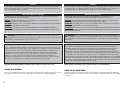
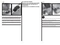
USING THE MANUAL
This manual is divided into sections to help make assembly easier to understand. Boxes () have
been placed next to each step. These help keep track of steps that have been completed.
ÜBER DIESE ANLEITUNG
Diese Anleitung ist zur Vereinfachung des Zusammenbaues in Sektionen unterteilt. Neben den
Sektionen befi nden sich Kästchen () die es Ihnen leichter machen den Arbeitsschritt als erledigt
abzuhaken.
This is a sophisticated hobby product. It must be operated with caution and common sense and
requires some basic mechanical ability. Failure to operate this Product in a safe and responsible
manner could result in injury or damage to the product or other property. This product is not
intended for use by children without direct adult supervision. Do not use with incompatible
components or alter this product in any way outside of the instructions provided by Horizon
Hobby, Inc. This manual contains instructions for safety, operation and maintenance. It is
essential to read and follow all the instructions and warnings in the manual, prior to assembly,
setup or use, in order to operate correctly and avoid damage or serious injury.
Dies ist ein hochentwickeltes Hobby-Produkt. Es muss mit Vorsicht und gesundem
Menschenverstand betrieben werden und benötigt gewisse mechanische Grundfähigkeiten.
Wird dieses Produkt nicht auf eine sichere und verantwortungsvolle Weise betrieben, kann
dies zu Verletzungen oder Schäden am Produkt oder anderen Sachwerten führen. Dieses
Produkt eignet sich nicht für die Verwendung durch Kinder ohne direkte Überwachung eines
Erwachsenen. Verwenden Sie das Produkt nicht mit inkompatiblen Komponenten oder verändern
es in jedweder Art ausserhalb der von Horizon Hobby, Inc. vorgegebenen Anweisungen. Diese
Bedienungsanleitung enthält Anweisungen für Sicherheit, Betrieb und Wartung. Es ist unbedingt
notwendig, vor Zusammenbau, Einrichtung oder Verwendung alle Anweisungen und Warnhinweise
im Handbuch zu lesen und zu befolgen, damit es bestimmungsgemäß betrieben werden kann und
Schäden oder schwere Verletzungen vermieden werden.
NOTICE
All instructions, warranties and other collateral documents are subject to change at the sole
discretion of Horizon Hobby, Inc. For up-to-date product literature, visit horizonhobby. com and
click on the support tab for this product.
HINWEIS
Alle Anweisungen, Garantien und anderen zugehörigen Dokumente können im eigenen Ermessen
von Horizon Hobby, Inc. jederzeit geändert werden. Die aktuelle Produktliteratur fi nden Sie auf
horizonhobby.com unter der Registerkarte „Support“ für das betreffende Produkt.
Meaning of Special Language
The following terms are used throughout the product literature to indicate various levels of
potential harm when operating this product:
NOTICE: Procedures, which if not properly followed, create a possibility of physical property
damage AND a little or no possibility of injury.
CAUTION: Procedures, which if not properly followed, create the probability of physical property
damage AND a possibility of serious injury.
WARNING: Procedures, which if not properly followed, create the probability of property
damage, collateral damage, and serious injury OR create a high probability of superfi cial injury.
Spezielle Bedeutungen
Die folgenden Begriffe werden in der gesamten Produktliteratur verwendet, um auf
unterschiedlich hohe Gefahrenrisiken beim Betrieb dieses Produkts hinzuweisen:
HINWEIS: Wenn diese Verfahren nicht korrekt befolgt werden, können sich möglicherweise
Sachschäden UND geringe oder keine Gefahr von Verletzungen ergeben.
ACHTUNG: Wenn diese Verfahren nicht korrekt befolgt werden, ergeben sich wahrscheinlich
Sachschäden UND die Gefahr von schweren Verletzungen.
WARNUNG: Wenn diese Verfahren nicht korrekt befolgt werden, ergeben sich wahrscheinlich
Sachschäden, Kollateralschäden und schwere Verletzungen ODER mit hoher Wahrscheinlichkeit
oberfl ächliche Verletzungen.
Age Recommendation: Not for children under 14 years. This is not a toy. Nicht geeignet für Kinder unter 14 Jahren. Dies ist kein Spielzeug.
WARNUNG: Lesen Sie die GESAMTE Bedienungsanleitung, um sich vor dem Betrieb mit
den Produktfunktionen vertraut zu machen. Wird das Produkt nicht korrekt betrieben, kann
dies zu Schäden am Produkt oder persönlichem Eigentum führen oder schwere Verletzungen
verursachen.
WARNING: Read the ENTIRE instruction manual to become familiar with the features of
the product before operating. Failure to operate the product correctly can result in damage
to the product, personal property and cause serious injury.
Seite wird geladen ...

4
SAFETY WARNINGS AND
PRECAUTIONS
Read and follow all instructions and safety
precautions before use. Improper use can result in
fi re, serious injury and damage to property.
Components
Use only with compatible components. Should any
compatibility questions exist, please refer to the
product instructions, component instructions or
contact the appropriate Horizon Hobby offi ce.
Flight
Fly only in open areas to ensure safety. It is
recommended fl ying be done at an RC fl ying fi eld.
Consult local ordinances before choosing a fl ying
location.
Batteries
Always follow the manufacturer’s instructions when
using and disposing of any batteries. Mishandling of
Li-Po batteries can result in fi re causing serious injury
and damage.
Small Parts
This kit includes small parts and should not be left
unattended near children as choking and serious
injury could result.
WARNUNGEN UND
SICHERHEITSVORKEHRUNGEN
Bitte lesen und befolgen Sie alle Anweisungen und
Sichervorkehrungen vor dem Gebrauch. Falscher,
nicht sachgemäßer Gebrauch kann Feuer, ernsthafte
Verletzungen und Sachbeschädigungen zur Folge
haben.
Komponenten
Verwenden Sie mit dem Produkt nur kompatible
Komponenten. Sollten Fragen zur Kompatibilität
auftreten, lesen Sie bitte die Produkt- oder
Bedienungsanweisung oder kontaktieren den Service
von Horizon Hobby.
Fliegen
Fliegen Sie um Sicherheit garantieren zu können, nur
in weiten offenen Gegenden. Wir empfehlen hier den
Betrieb auf zugelassenen Modellfl ugplätzen. Bitte
beachten Sie lokale Vorschriften und Gesetze, bevor
Sie einen Platz zum Fliegen wählen.
Akkus
Folgen Sie immer den Herstelleranweisungen bei
dem Gebrauch oder Entsorgung von Akkus. Falsche
Behandlung von LiPo Akkus kann zu Feuer mit
Körperverletzungen und Sachbeschädigung führen.
Kleinteile
Dieser Baukasten beinhaltet Kleinteile und darf nicht
unbeobachtet in der Nähe von Kindern gelassen
werden, da die Teile verschluckt werden könnten mit
ernsthaften Verletzung zur Folge.
AVERTISSEMENTS RELATIFS À
LA SÉCURITÉ
Lisez et suivez toutes les instructions relatives à la
sécurité avant utilisation. Une utilisation inappropriée
peut entraîner un incendie, de graves blessures et
des dégâts matériels.
Composants
Utilisez uniquement des composants compatibles. Si
vous avez des questions concernant la compatibilité,
référez-vous à ce manuel ou contactez le service
technique Horizon Hobby.
Le vol
Volez uniquement dans des zones dégagées pour un
maximum de sécurité. Il est recommandé d’utiliser
les pistes des clubs d’aéromodélisme. Consultez
votre mairie pour connaître les sites autorisés.
Les batteries
Suivez toujours les instructions du fabricant de vos
batteries. Une mauvaise manipulation d’une batterie
Li-Po peut entraîner un incendie causant de graves
dégâts matériels et des blessures corporelles.
Petites pièces
Ce kit contient des petites pièces qui ne doivent pas
être laissées à la portée des enfants, ces pièces sont
dangereuses pour eux et peuvent entraîner de graves
blessures.
AVVERTIMENTI E PRECAUZIONI
PER LA SICUREZZA
Prima dell’uso leggere attentamente tutte le istruzioni
e le precauzioni per la sicurezza. In caso contrario si
potrebbero procurare incendi, danni o ferite.
Componenti
Usare solo componenti compatibili. Se ci fossero
dubbi riguardo alla compatibilità, è opportuno far
riferimento alle istruzioni relative al prodotto o ai
componenti oppure rivolgersi al reparto Horizon
Hobby di competenza.
Volo
Per sicurezza volare solo in aree molto ampie. Meglio
se si va su campi volo autorizzati per modellismo.
Consultare le ordinanze locali prima di scegliere una
ubicazione.
Batterie
Quando si maneggiano o si utilizzano le batterie,
bisogna attenersi alle istruzioni del costruttore; il
rischio è di procurare incendi, specialmente con le
batterie LiPo, con danni e ferite serie.
Piccole parti
Questo kit comprende delle parti di piccole dimensioni
e non lo si può lasciare incustodito se c’è la presenza
di bambini che li possono inghiottire e rimanere
soffocati o intossicati.

5
SAFE OPERATING
RECOMMENDATIONS
• Inspect your model before every fl ight to ensure it
is airworthy.
• Be aware of any other radio frequency user who
may present an interference problem.
• Always be courteous and respectful of other users
in your selected fl ight area.
• Choose an area clear of obstacles and large
enough to safely accommodate your fl ying activity.
• Make sure this area is clear of friends and
spectators prior to launching your aircraft.
• Be aware of other activities in the vicinity of your
fl ight path that could cause potential confl ict.
• Carefully plan your fl ight path prior to launch.
• Abide by any and all established AMA National
Model Aircraft Safety Code.
EMPFEHLUNGEN ZUM
SICHEREN BETRIEB
• Überprüfen Sie zur Flugtauglichkeit ihr Modell vor
jedem Flug.
• Beachten Sie andere Piloten deren
Sendefrequenzen ihre Frequenz stören könnte.
• Begegnen Sie anderen Piloten in ihrem Fluggebiet
immer höfl ich und respektvoll.
• Wählen Sie ein Fluggebiet, dass frei von
Hindernissen und groß genug ist.
• Stellen Sie vor dem Start sicher, dass die Fläche
frei von Freunden und Zuschauern ist.
• Beobachten Sie den Luftraum und andere
Flugzeuge/Objekte die ihren Flugweg kreuzen und zu
einem Konfl ikt führen könnten.
• Planen Sie sorgfältig ihren Flugweg vor dem Start.
CONSIGNES DE SÉCURITÉ
CONCERNANT L’UTILISATION
• Inspectez votre modèle avant chaque vol.
• Surveillez les fréquences utilisées à proximité.
• Soyez toujours courtois et respectueux des autres
utilisateurs de la zone de vol.
• Choisissez une zone dégagée de tout obstacle et
suffi samment grande pour voler en toute sécurité.
• Contrôlez que la zone est libre de spectateurs
avant de lancer votre modèle.
• Soyez conscient des autres activités aux alentours
de votre vol, risque de confl it potentiel.
• Planifi ez votre vol avant de le commencer.
RACCOMANDAZIONI PER
OPERARE IN SICUREZZA
• Controllare attentamente il modello prima di ogni
volo per accertarsi che sia idoneo.
• Essere consapevoli che un altro utente della
frequenza in uso, potrebbe procurare delle
interferenze.
• Essere sempre cortesi e rispettosi nei confronti
degli altri utilizzatori dell’area in cui ci si trova.
• Scegliere un’area libera da ostacoli e abbastanza
ampia da permettere lo svolgimento del volo in
sicurezza.
• Prima del volo verifi care che l’area sia libera da
amici e spettatori.
• Stare attenti alle altre attività che si svolgono in
vicinanza della vostra traiettoria di volo, per evitare
possibili confl itti.
• Pianifi care attentamente il volo prima di lanciare il
modello.
• Rispettare sempre scrupolosamente le regole
stabilite dall’associazione locale.

6
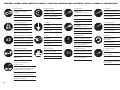
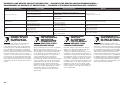
ASSEMBLY SYMBOL GUIDE/MONTAGE SYMBOLE /GUIDE DES SYMBOLES POUR ASSEMBLÉE /GUIDA AI SIMBOLI DI ASSEMBLAGGIO
5
30
OIL
L
R
L
R
x2
Use a pencil
Verwenden Sie einen Bleistift
Utilisez un crayon à papier
Usare una matita
Use medium CA
Mittelfl üssigen
Sekundenkleber verwenden
Utilisez de la cyanoacrylate
moyenne
Usare CA media
Use thin CA
Dünnfl üssigen
Sekundenkleber verwenden
Utilisez de la cyanoacrylate fi ne
Usare CA fi ne
Use a felt-tipped pen
Verwenden Sie einen Faserstift
Utilisez un feutre fi n effaçable
Usare un pennarello
Use 5-minute epoxy
Verwenden Sie 5 Minuten Epoxy
Utilisez de l’époxy 5 minutes
Usare una resina epossidica con
indurimento di 5 minuti
Ensure free rotation
Rotation sicherstellen
Permettez une rotation libre
Assicurarsi rotazione libera
Push tightly
Fest drücken
Serrez fortement
Spingere forte
Apply oil
Öl verwenden
Appliquez lubrifi ant
Applicare olio
Attach temporarily
Vorübergehend anbringen
Attachez temporairement
Attaccare temporaneamente
Apply threadlock
Schraubensicherungslack
verwenden
Utilisez du frein fi let
Applicare fuido threadlock
Assemble right and left
Links und rechts montieren
Assemblez à droite et à gauche
Assemblare destra e sinistra
Repeat multiple times (as indicated)
Vorgang wiederholen (wie angezeigt)
Répétez comme indiqué
Ripetere piu’ volte (come indicato)
Ensure proper orientation
Ausrichtung/Richtung sicherstellen
Vérifi ez la bonne orientation
Assicurarsi dell’appropriato
orientamento
Use screw to cut threads and
thin CA to harden
Erstellen Sie mit dem Eindrehen von einer
Schraube ein Gewinde und härten dieses
mit dünnfl üssigen Sekundenkleber.
Utilisez une vis pour tarauder la pièce et
de la colle CA pour renforcer les fi lets
Usare una vite per creare la fi lettatura e
la colla CA per indurirla.
Use 30-minute epoxy
Verwenden Sie 30 Minuten Epoxy
Utilisez de l’époxy 30 minutes
Usare una resina epossidica con
indurimento di 30 minuti
Fully tighten
Vollständig festziehen/
festschrauben
Serrez complètement
Stringere al massimo
Use hobby knife with
#11 blade
Verwenden Sie ein Hobbymesser
mit # 11 Klinge
Utilisez un Couteau: Lame numéro
11
Usare taglierino per hobbistica con
lama numero 11

7
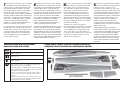
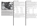
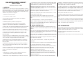
165 in (4.20 m)
2030 in
2
(131 dm
2
)
85.5 in (2.17 m)
22.0 lb (10.0 kg)
5-channel (or greater) with 6 standard size, high-torque
servos and 2 mini servos. 5- and 6-channel systems will
require reversed servos or matchboxes.
5 Kanal (oder größer) mit 6 High Torque Servos in Standard
Größe und 2 Mini Servos. 5- und 6-Kanal Systeme erfordern
reversierte Servos oder Matchboxes.
5 voies ou + avec 6 puissants servos de format standard
et 2 minis servos. Les voies 5 et 6 nécessiteront d’être
inversées.
Almeno 5 canali (o più) con 6 servi standard e 2 mini servi.
Un sistema del genere deve avere la possibilità di invertire i
servi direttamente o tramite “Matchbox”.
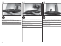
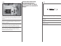
SPECIFICATIONS/SPEZIFIKATIONEN/
SPÉCIFICATIONS/SPECIFICHE
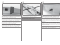
LARGE PARTS LAYOUT/BAUTEILE (OHNE KLEINTEILE)/
GRANDES PIÈCES/SCHEMA DEI COMPONENTI GRANDI
T
hank you for purchasing this 1/4-scale model
of the Red Bull sponsored aerobatic Blanik
sailplane. With its unique forward swept wings
and upswept horizontal stabilizer, the E-fl ite
®
Blanik sailplane offers a distinct, unmistakable
presence in fl ight. The full sized Blanik is an
airshow sensation and this model is no different.
Perfectly suited for aerotowing or slope soaring,
the Blanik is an aerobatic force to reckon with.
Loops, rolls, inverted fl ight and even snapping
maneuvers show off the Blanik sailplane’s
prowess as an aerobatic contender despite its
cold war era roots as a basic trainer.
Be sure to read this manual for important safety
considerations and assembly steps. Take note
that the center of gravity on this model is much
further forward than one might expect due to
the forward swept wings. Be sure to add the
necessary weight to the nose to achieve the
correct center of gravity.
V
ielen Dank, dass Sie sich für den 1/4 Scale
Red Bull Blanik entschieden haben. Mit den
einzigartigen nach vorne gepfeilten Tragfl ächen
und dem Höhenruder in V-Form besitzt der
E-fl ite Blanik einen unverwechselbaren Auftritt.
Das Original ist bei vielen Airshows die absolute
Sensation und das Modell steht dem in nichts
nach. Der Blanik ist perfekt für den Schlepp-
oder Hangfl ug ausgelegt und im Segelkunstfl ug
ein absolutes Traumfl ugzeug. Ob Loopings,
Rollen, Rückenfl ug oder selbst gerissene
Manöver zeigen das großen Potential dieses
Trainers aus Zeiten des kalten Krieges.
Bitte lesen Sie die Bedienungsanleitung mit den
Sicherheitshinweisen und Baustufen sorgfältig.
Bitte beachten Sie, dass der Schwerpunkt des
Modells bedingt durch die nach vorne gepfeilten
Tragfl äche viel weiter vorne als erwartet liegt.
Stellen Sie sicher, dass Sie ausreichend Gewicht
in die Nase des Modell gegeben haben um den
korrekten Schwerpunkt zu erreichen.
N
ous vous remercions pour l’achat du planeur
Blanik à l’échelle 1/4 sponsorisé par Red
Bull. Grâce à ses ailes en fl èche inverse et
son stabilisateur en deux parties, le planeur
Blanik E-fl ite a une allure vraiment unique
en vol. Cette réplique attire les foules tout
comme le modèle grandeur. Parfait pour le
remorquage ou le vol de pente, le Blanik est
également très performant en vol acrobatique,
boucles, tonneaux, vol dos, bien que la période
de la guerre froide l’ait restreint à un modèle
d’entraînement basique.
Veuillez lire ce manuel, il contient des
informations importantes relatives à la sécurité
et à l’assemblage du modèle. Remarquez que
sur ce modèle le centre de gravité est placé
plus en avant que sur les autres planeurs à
cause de son aile en fl èche inverse. Prenez soin
d’ajouter le lest nécessaire dans le nez afi n
d’obtenir le centrage correct.
G
razie per aver acquistato questo modello
di aliante acrobatico Blanik sponsorizzato
Red Bull, in scala 1:4. Con la sua ala
particolare a freccia negativa (in avanti) e lo
stabilizzatore slanciato, l’aliante Blanik E-fl ite ha
un profi lo inconfondibile in volo. Il Blanik reale
è un’attrazione nelle manifestazioni aeree, e
questo modello non è diverso. Perfettamente
adatto al traino o al volo in pendio, ha una
capacità acrobatica con cui confrontarsi.
Looping, tonneau, volo rovescio e altre
manovre provano la sua abilità come aereo
acrobatico anche se era stato classifi cato come
addestratore basico.
Bisogna leggere questo manuale per le
considerazioni importanti riguardo alla sicurezza
e alla procedura di montaggio. Bisogna anche
notare che il baricentro di questo modello
è molto più avanti di quanto uno potrebbe
aspettarsi ed è dovuto alla freccia negativa
dell’ala. Verifi care che nel naso ci sia il peso
necessario per posizionare correttamente il
baricentro.

8
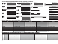
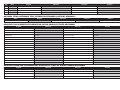
RECOMMENDED ITEMS/ERFORDERLICHE TEILE/ELÉMENTS REQUIS/ARTICOLI NECESSARI
Qty Part English Deutsch Français Italiano
6 SPMSA6030 A6030 Digital Aircraft Servo - High Torque Spektrum Digitalservo A6030 Hochlast Air Giant Scale Servo A6030 Digital, Couple élevé Servo digitale per aereo - coppia elevata
2 SPMSA5040 A5040 Mini Digital Aircraft Metal Gear Servo Spektrum A5040 Mini Digital MG Flug - Servo Mini servo digital A5040 à pignons métal Mini servo digitale per aereo con ingran. metallo
1 SPMAR7010 AR7010 7-Channel DSMX
®
Receiver Spektrum AR7010 7 Kanal DSM X Empfänger Récepteur AR7010 7 voies DSMX Ricevitore 7 canali DSMX
4 SPMA3007 Heavy-Duty Servo Extension 48” Spektrum Hochleistungs Servokabelverlängerung 121.92 cm Rallonge de servo longueur 120 cm Prolunga servi da 110cm per carichi pesanti
2 SPMA3004 Heavy-Duty Servo Extension 18” Spektrum Hochleistungs Servokabelverlängerung 45.72 cm Rallonge de servo longueur 45 cm Prolunga servi da 45cm per carichi pesanti
REPLACEMENT PARTS/ERSATZTEILE/PIÈCES DE RECHANGE/RICAMBI
Part English Deutsch Français Italiano
EFL4910 L-13 Blanik 4.2 m E-fl ite Blanik L13 4,2m ARF L-13 Blanik 4.2m L-13 Blanik 4.2 m
EFL491001 Right Wing Panel E-fl ite Blanik L13: Tragfl äche rechts Aile droite Semiala destra
EFL491002 Left Wing Panel E-fl ite Blanik L13: Tragfl äche links Aile gauche Semiala sinistra
EFL490103 Fuselage E-fl ite Blanik L13: Rumpf Fuselage Fusoliera
EFL491004 Fin and Rudder Assembly E-fl ite Blanik L13: Finne und Seitenruder Dérive complète Gruppo direzionale e timone
EFL491005 Horizontal Stabilizer E-fl ite Blanik L13: Höhenleitwerk und Ruder Stabilisateur Stabilizzatore orizzontale
EFL491006 Main Hardware Pack A E-fl ite Blanik L13: Kleinteile Sachet d’accessoires A Pacco A, viteria principale
EFL491007 Landing Gear Pack E-fl ite Blanik L13: Fahrwerk u. Rad Sachet du train d’atterrissage Pacco per carrello
EFL491008 Wing Tube Carbon Rod Pack
E-fl ite Blanik L13: Flächenverbinder u.
Carbonschubstangen
Clé d’aile en carbone Pacco bacchetta carbonio per tubo ala
2-56 threaded cable end (4)
2-56 Augenbolzen (4)
Oeillet fi leté 2-56 (4)
2-56 terminale fi lettato (4)
2-56 push rod (4)
2-56 Gestänge (4)
Biellette 2-56 (4)
2-56 barretta comando (4)
4-40 push rod/short (2)
4-40 Gestänge kurz (2)
Biellette courte 4-40 (2)
4-40 barretta comando/corta (2)
4-40 push rod/long (2)
4-40 Gestänge lang (2)
Biellette longue 4-40 (2)
4-40 barretta comando/lunga (2)
2-56 metal clevis (8)
2-56 Metall Gabelkopf (8)
Chappe métal 2-56 (8)
2-56 forcella metallica (8)
4-40 metal clevis (9)
4-40 Metall Gabelkopf (9)
Chappe métal 4-40 (9)
4-40 forcella metallica (9)
M2 lock nut (1)
M2 Stopmutter (1)
Ecrou frein M2 (1)
M2 dado autobloccante (1)
4-40 nut (9)
4-40 Mutter (9)
Ecrou 4-40 (9)
4-40 dado (9)
2-56 nut (8)
2-56 Mutter (8)
Ecrou 2-56 (8)
2-56 dado (8)
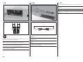
FASTENERS/VERBINDUNGSELEMENTE/LIAISONS/ELEMENTI DI FISSAGGIO
M3 x 10 mm self-tapping screw (6)
M3 x 10mm selbstschneidene Schraube(6)
Vis auto-taraudeuse M3x10mm (6)
M3 x 10 mm vite autofi lettante (6)
M2 x 8 mm self-tapping screw (16)
M 2 x8 mm selbstschneidene Schraube (16)
Vis auto-taraudeuse M2x8mm (16)
M2 x 8 mm vite autofi lettante (16)
M3 x 10 mm fl at socket head (6)
M3 x 10 Senkkopfschraube (6)
Vis à tête fraisée M3x10mm (6)
M3 x 10 mm a testa piatta (6)
M3 x 25 socket head screw (4)
M3 x 25 Inbusschraube (4)
Vis CHC M3 x 25 (4)
M3 x 25 vite con testa a brugola (4)
M3 washer (4)
M3 Unterlegscheibe (4)
Rondelle M3 (4)
M3 rondella (4)
M2 x 20 mm screw (1)
M2 x 20 Inbusschraube (1)
Vis CHC M2x20mm (1)
M2 x 20 mm vite (1)
M4 x 30 wingbolt (2)
M4 x30 Tragfl ächenbolzen (2)
Vis papillon M4x30 (2)
M4 x 30 bullone alettato (2)

9
OPTIONAL ITEMS/OPTIONALE TEILE/ELÉMENTS OPTIONNELS/ARTICOLI OPZIONALI
REQUIRED TOOLS/BENÖTIGTES WERKZEUG/OUTILS REQUIS/ATTREZZI NECESSARI
REQUIRED ADHESIVES/ERFORDERLICHE KLEBSTOFFE/TYPES DE COLLES/ADESIVI NECESSARI
Part English Deutsch Français Italiano
EFL491009 440 mm Electric Spoilers E-fl ite Blanik L13: Elektrische Störklappen Aérofreins électriques 440mm Aerofreni elettrici da 44cm
English Deutsch Français Italiano
Covering iron Bügeleisen Fer à entoiler Ferro per rivestimenti
Drill bit: 1/16-inch, 5/32-inch Bohrer: 1.5mm, 2mm Foret : 1.5mm, 2mm Punte per trapano: 1.5mm, 2mm
Electrical tape-clear Isolierband klar Ruban adhésif transparent Nastro adesivo trasperente
Felt-tipped pen Faserstift Feutre fi n effaçable Pennarello
Hemostats Klemme Pince Hemostat Forbici
Hobby knife: #11 blade Hobbymesser mit # 11 Klinge Couteau : Lame numéro 11 Taglierino: #11 lama
Hobby scissors Hobbyschere Ciseaux Forbici per hobby
Low-tack tape Klebeband m. geringer Klebekraft Adhésif de masquage Nastro a bassa aderenza
Needle nose pliers Spitzzange Pince fi ne Pinze a becco stretto
Pencil Stift Crayon à papier Matita
Phillips screwdriver: #1, #2 Phillips Schraubendreher: #1, #2 Tournevis cruciforme: #1, #2 Cacciavite a croce: #1, #2
Pin vise Handbohrer Porte forêts Morsa stretta
Ruler Lineal Réglet Righello
Sandpaper Schleifpapier Papier abrasif Carta vetrata
Side cutters Seitenschneider Pince coupante Lama laterale
String Schnur Ficelle Spago
3/8-inch heat-shrink tubing 3/8 ich (9,5mm) Schrumpfschlauch Gaine thermo-rétractable diam. 10mm Tubo termorestringente da 10mm
English Deutsch Français Italiano
5-minute epoxy 5 Minuten Epoxy Colle Epoxy 5 minutes Colla epoxy 5 minuti
30-minute epoxy 30 Minuten Epoxy Colle Epoxy 30 minutes Colla epoxy 30 minuti
Thin CA Sekundenkleber dünnfl üssig Colle cyano fi ne Sottile CA
Medium CA Sekundenkleber mittel Colle cyano moyenne Medio CA
Qty Part English Deutsch Français Italiano
1 SPMA3008 Heavy-Duty Y-Harness, 6-inch Spektrum Hochleistungs Y- Servokabel Cordon Y longueur 15 cm Prolunga a Y da 15cm per carichi pesanti
1 SPM9530 Spektrum™ 3-Wire Switch Harness Spektrum Schalterkabel 3 Anschlüsse Interrupteur Spektrum à 3 fi ls Interruttore Spektrum 3 fi li
1 JRPB4550 Extra Receiver Pack 3000mAh 6V Ni-Cd Flat Empfängerakku 3000mAh 6 Volt Flach Batterie de réception Ni-Cd 6V 3000mA Batteria piatta extra da 3000mAh 6V
1 DUB671 Super Strength Long Servo Arm Servoarm lang Bras de servo long et renforcé Squadretta lunga per servo

10
BEFORE STARTING ASSEMBLY
• Remove parts from bag.
• Inspect fuselage, wing panels, rudder and stabilizer
for damage.
• If you fi nd damaged or missing parts, contact your
place of purchase.
If you fi nd any wrinkles in the covering, use a heat gun
(HAN100) and covering glove (HAN150) or covering
iron (HAN101) with a sealing iron sock (HAN141) to
remove them. Use caution while working around areas
where the colors overlap to prevent separating the
colors.
• Charge transmitter and fl ight battery.
• Center trims and sticks on your transmitter.
• For a computer radio, create a model memory for
this particular model.
• Bind your transmitter and receiver, using your radio
system’s instructions.
IMPORTANT: Rebind the radio system once all
control throws are set. This will keep the servos from
moving to their endpoints until the transmitter and
receiver connect. It will also guarantee the servo
reversal settings are saved in the radio system.
VOR DEM ZUSAMMENBAU
• Entnehmen Sie zur Überprüfung jedes Teil der
Verpackung.
• Überprüfen Sie den Rumpf, Tragfl ächen, Seiten-
und Höhenruder auf Beschädigung.
• Sollten Sie beschädigte oder fehlende Teile
feststellen, kontaktieren Sie bitte den Verkäufer.
Zum Entfernen von Falten in der Bespannung
verwenden Sie den Heißluftfön (HAN100)
und Bespannhandschuh (HAN150) oder das
Folienbügeleisen (HAN141). Bitte achten Sie bei
überlappenden Farben, dass Sie diese sich bei dem
Bearbeitung nicht trennen.
• Laden Sie den Sender und den Flugakku.
• Zentrieren der Trimmungen und Sticks auf dem
Sender.
• Sollten Sie einen Computersender verwenden,
resetten Sie einen Speicherplatz und benennen ihn
nach dem Modell.
• Sender und Empfänger jetzt nach den
Bindeanweisung des Herstellers binden.
WICHTIG: Wir empfehlen dringend nachdem alle
Einstellungen vorgenommen worden sind, das Modell
neu zu binden. Dieses verhindert, dass die Servos
in die Endanschläge laufen bevor sich Sender und
Empfänger verbunden haben. Es garantiert auch,
dass die Servoreverseeinstellungen in der RC Anlage
gesichert sind.
AVANT DE COMMENCER
L’ASSEMBLAGE
• Retirez toutes les pièces des sachets pour les
inspecter.
• Inspectez soigneusement le fuselage, les ailes et
les empennages.
• Si un élément est endommagé, contactez votre
revendeur.
Si l’entoilage présente quelques plis, vous pouvez les
lisser en utilisant le pistolet à air chaud (HAN100)
et le gant (HAN150) ou le fer à entoiler (HAN101)
avec la chaussette de protection (HAN141). Agissez
soigneusement dans les zones ou plusieurs couleurs
d’entoilage sont superposées afi n d’éviter de les
séparer.
• Chargez les batteries de l’émetteur et de
propulsion.
• Mettez les trims et les manches de votre émetteur
au neutre.
• Si vous utilisez une radio programmable,
sélectionnez une mémoire libre afi n d’y enregistrer
les paramètres de ce modèle.
• Nous vous recommandons d’affecter maintenant le
récepteur à l’émetteur en suivant les instructions
fournies avec votre radio.
IMPORTANT: Il est hautement recommandé
de ré-affecter le système une fois que les courses
seront réglées. Cela empêchera les servos d’aller en
butée lors de la connexion du système. Cela garantit
également que la direction des servos est enregistrée
dans l’émetteur.
PRIMA DI INIZIARE IL
MONTAGGIO
• Togliere tutti i pezzi dalla scatola.
• Verifi care che la fusoliera, l’ala e i piani di coda non
siano danneggiati.
• Se si trovano parti danneggiate, contattare il
negozio da cui è stato acquistato.
Se si trovano delle rughe nella ricopertura, si possono
togliere usando una pistola ad aria calda (HAN100)
e guanto per ricopertura (HAN150), oppure un
ferro per ricopertura (HAN101) con la sua calza
di protezione (HAN141). Usare cautela quando si
lavora in aree del rivestimento dove ci sono dei colori
sovrapposti, per evitare la loro separazione.
• Caricare il trasmettitore e la batteria di volo.
• Centrare stick e trim sul trasmettitore.
• Con una radio computerizzata creare una nuova
memoria per questo modello.
• Facendo riferimento alle istruzioni del
radiocomando, connettere (bind) trasmettitore e
ricevitore.
IMPORTANTE: Ripetere la procedura di
connessione una volta regolate le corse, per evitare
che i servi vadano a fi ne corsa. Garantirà anche che le
impostazioni di inversione del servo vengano salvate
nel sistema radio.
Seite wird geladen ...
Seite wird geladen ...

13
6
x4
L
R
L
R
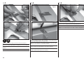
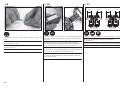
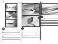
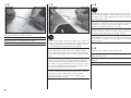
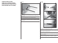
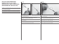
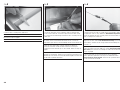
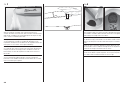
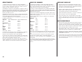
Align the servos on the aileron and fl ap servo doors as shown. Pay
attention to prepare a left and right side.
Richten Sie die Servos auf den Abdeckungen wie abgebildet aus. Achten
Sie darauf eine rechte und linke Seite vorzubereiten.
Placez les servos d’ailerons et de volets sur les couvercles comme sur
l’illustration. Préparez le côté gauche et le côté droit.
Allineare i servi ai coperchi portaservi per alettoni e fl ap, come si vede in
fi gura. Attenzione a preparare il lato destro e sinistro.
7
x4
L
R
L
R
Mark the locations where the blocks need to mount.
Markieren Sie die Position der Befestigungsblöcke.
Marquez les emplacements des blocs de fi xation des servos.
Segnare la posizione di montaggio dei blocchetti.
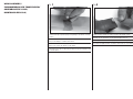
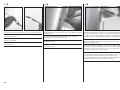
8
Hold the servo in place on the mounting blocks and mark screw locations
with a felt tipped pen.
Halten Sie das Servo in Position und markieren die Positionen der
Befestigungsschrauben mit einem Faserstift.
Maintenez le servo en place sur les blocs de fi xation pour marquer
l’emplacement des vis.
Tenere il servo in posizione sui blocchetti e segnare la posizione delle viti
con un pennarello.
Aileron/
Querruder/
Ailerons/
Alettone/
Front of the wing/
Vorderseite der
Tragfl äche/
Bord d’attaque de l’aile/
Bordo di entrata ala
Flap/
Klappen/
Volets/
Flap
4 mm 4 mm
3 mm3 mm
Front of the wing/
Vorderseite der
Tragfl äche/
Bord d’attaque de l’aile/
Bordo di entrata ala
Seite wird geladen ...
Seite wird geladen ...
Seite wird geladen ...

17
3
x2
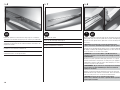
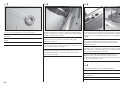
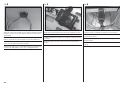
Connect an 18” extension to the spoiler lead, then shrink a 1 1/2” piece
of 3/8” shrink tubing over the connection.
Schließen Sie die 45,72cm lange Verlängerung an das Störklappenkabel
an und sichern die Verbindung mit einem 4 cm langen Stück 9,5mm
breiten Schrumpfschlauch.
Connectez une rallonge de 45 cm à chaque prise d’aérofrein et placez un
morceau de gaine thermo-rétractable de 4cm de long pour sécuriser la
connexion.
Collegare la prolunga da 45cm al cavetto dell’aerofreno, fi ssandola con
un pezzo di termorestringente da 10mm di diametro, lungo 3,8cm.
4
x2
Tie the string located inside the wing around the end of the extension.
Pull the lead through the wing.
Knoten Sie die Schnur aus der Tragfl äche um das Ende des
Verlängerungkabels. Ziehen Sie das Kabel durch die Tragfl äche.
Nouez de la fi celle autour de la prise de servo de la rallonge. Tirez la
prise à l’intérieur de l’aile.
Legare all’estremità della prolunga uno spago inserito nell’ala. Tirare il
cavo attraverso l’ala.
5
x2
Connect the spoiler to a servo driver or your radio system and fully open
the spoiler.
Schließen Sie die Störklappe an einen Servoanschluß des Empfängers
ihrer Fernsteuerung an und fahren die Klappe vollständig aus.
Connectez l’aérofrein à la rallonge de servo et déployez-le entièrement.
Collegare l’aerofreno ad un provaservi o al radiocomando per aprirlo
completamente.

18
6
x2
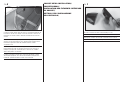
Mount the spoiler to the channel in the wing using a #1 screwdriver.
Thread the three included self-tapping screws into the pre-drilled holes.
Setzen Sie die Störklappe mit einem #1 Schraubendreher in die
Tragfl äche ein und drehen die drei selbstschneidenen Schrauben in die
vorgebohrten Löcher.
Fixez l’aérofrein dans son emplacement en utilisant 3 vis auto-
taraudeuses et un tournevis cruciforme #1.
Fissare l’aerofreno all’ala usando un cacciavite #1. Avvitare le 3 viti
autofi lettanti incluse, nei fori già esistenti.
7
x2
Fully retract the spoiler.
Fahren Sie die Störklappe vollständig ein.
Rentrez entièrement l’aérofrein.
Chiudere completamente l’aerofreno.
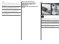
8
5
x2
Apply a small amount of 5-minute epoxy to the retractable center portion
of the spoiler only, then tape the spoiler cover in place. Avoid getting
epoxy on the outer portion of the spoiler that is fi xed in the wing or the
mechanism.
NOTICE: Do not allow epoxy to get into the mechanism of the
spoilers or the motor will fail when you attempt to open the spoilers.
Streichen Sie ein wenig 5 Minuten Epoxy auf das ausfahrbare Mittelteil
der Klappe und kleben die Störklappenabdeckung auf. Bitte achten Sie
darauf den Kleber nur auf diesen Teil zu geben.
HINWEIS: Lassen Sie keinen Kleber in den Mechanismus der
Störklappe gelangen, da sonst der Motor oder die Klappe im Betrieb
klemmen könnte.
Appliquez une petite quantité de colle époxy 5 minutes sur la partie
centrale de l’aérofrein et uniquement sur cette partie, puis appliquez
l’habillage de l’aérofrein. Evitez de mettre de la colle époxy sur le mé-
canisme ou la partie fi xe de l’aérofrein.
REMARQUE : Ne pas mettre de la colle époxy dans le mécanisme
des aérofreins sous peine d’endommager le moteur en tentant de
déployer les aérofreins.
Mettere una piccola quantità di colla epoxy 5 minuti solo sulla parte
mobile dell’aerofreno per incollare il rivestimento. Evitare di mandare la
colla anche sulle parti fi sse o sul meccanismo dell’aerofreno.
AVVISO: non lasciare che la colla vada sul meccanismo
dell’aerofreno, altrimenti il suo motore si potrebbe bruciare quando si
tenta di aprire l’aerofreno.

19
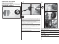
FLAP INSTALLATION/
EINBAU DER LANDEKLAPPEN/
INSTALLATION DES VOLETS/
INSTALLAZIONE FLAP/
1
x2
Connect the 18” servo extension to the fl ap servo lead, then shrink a
1 1/2” piece of 3/8” shrink tubing over the connection.
Schließen Sie die 45,72cm lange Verlängerung an das Servoklappenkabel
an und sichern die Verbindung mit einem 4 cm langen Stück 9,5mm
breiten Schrumpfschlauch.
Connectez une rallonge de 45 cm à chaque prise de servo de volet et
placez un morceau de gaine thermo-rétractable de 4cm de long pour
sécuriser la connexion.
Collegare la prolunga da 45cm al cavetto dei servi fl ap, fi ssandola con un
pezzo di termorestringente da 10mm di diametro, lungo 3,8cm.
2
x2
Tie the string located inside the wing around the end of the extension.
Pull the lead through the wing.
Knoten Sie die Schnur aus der Tragfl äche um das Ende des
Verlängerungkabels. Ziehen Sie das Kabel durch die Tragfl äche.
Nouez de la fi celle autour de la prise de servo de la rallonge. Tirez la
prise à l’intérieur de l’aile.
Legare all’estremità della prolunga uno spago inserito nell’ala. Tirare il
cavo attraverso l’ala.
Seite wird geladen ...
Seite wird geladen ...
Seite wird geladen ...
Seite wird geladen ...

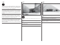
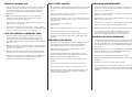
24
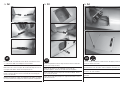
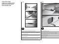
3
Mount the remaining wheel support plate.
Schrauben Sie die zweite Halteplatte an.
Montez la deuxième platine.
Montare l’altro supporto per la ruota.
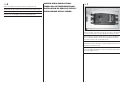
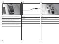
4
Install the wheel assembly into the fuselage with the taller vertical
section to the front as shown in the above diagram.
Setzen Sie den Radträger mit der größeren Seite nach vorne zeigend wie
abgebildet in den Rumpf ein.
Installez le train dans le fuselage en plaçant le côté le plus haut vers
l’avant du fuselage comme sur l’illustration.
Montare tutto il gruppo nella fusoliera con la sezione verticale più alta
verso l’avanti, come si vede in questa fi gura.
5
Secure the wheel assembly from inside the fuselage using four 3 x
25mm bolts and washers and a 2.5 mm hex driver. Use threadlock on
each screw.
Schrauben Sie den Radträger von der Innenseite mit vier 3 x 25mm
Schrauben und Unterlegscheiben mit einem Inbusschlüssel fest. Sichern
Sie jede Schraube mit Schraubensicherungslack.
Fixez le train dans le fuselage en utilisant 4 vis M3 x 25 et 4 rondelles
avec une clé hexagonale de 2.5mm. Utilisez du frein fi let sur chaque vis.
Fissare il gruppo ruota dall’interno della fusoliera usando 4 bulloni da
3 x 25mm con rondella e un cacciavite con testa esagonale da 2,5mm.
Usare del frenafi letti su ogni bullone.
Front/
Vorne/
Avant/
Davanti/
Seite wird geladen ...
Seite wird geladen ...
Seite wird geladen ...

28
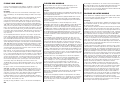
9
L
R
L
R
Install the servo using the self-tapping screws included with the servo.
Center the servo and install the servo horn.
Schrauben Sie die Servos mit den selbstschneidenen Schrauben fest.
Zentrieren Sie das Servo und schrauben das Servohorn fest.
Installez les servos en utilisant les vis auto-taraudeuses fournies avec les
servos. Placez les servos au neutre et installez les bras.
Fissare il servo con le viti autofi lettanti fornite insieme ai servi. Centrare
il servo e montare le squadrette.
10
Assemble the linkage and connect the clevises to the servo arm and
control horn.
Montieren Sie die Anlenkung und schließen die Gabelköpfe an Servoarm
und Ruderhorn an.
Assemblez la tringlerie et connectez-la entre le bras de servo et le
guignol.
Assemblare le barrette dei comandi e collegare le loro forcelle alle
squadrette di servo ed elevatore
11
Repeat steps 6–10 to assemble the other horizontal stabilizer half.
Wiederholen Sie die Schritte 6–10 um die zweite Höhenruderhälfte zu
montieren.
Répétez les étapes de 6 à 10 pour assembler le deuxième demi-stab.
Ripetere i passi da 6 a 10 per montare l’altra metà dello stabilizzatore
orizzontale.
14 mm 14 mm
66 mm
Seite wird geladen ...
Seite wird geladen ...

31
VERTICAL STABILIZER INSTALLATION/
EINBAU DES SEITENLEITWERKS/
INSTALLATION DE LA DÉRIVE/
INSTALLAZIONE IMPENNAGGIO VERTICALE/
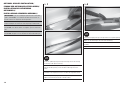
1
Sand the mating surface of the vertical stabilizer and fuselage for good
adhesion
Schleifen Sie die Klebefl äche des Seitenleitwerks am Rumpf für eine
saubere Verklebung an.
Poncez la surface de contact de la dérive pour assurer une bonne
adhérence.
Per avere una buona aderenza, carteggiare la superfi cie del direzionale
che va ad appoggiarsi sulla fusoliera.
2
30
Apply 30-minute epoxy to the included carbon rods to align the vertical
stabilizer. Install the rods into the vertical stabilizer.
Streichen Sie 30 Minuten Epoxy auf die Carbonstangen und kleben diese
in das Seitenleitwerk ein.
Appliquez de la colle époxy 30 minutes sur les tubes en carbone servant
à l’alignement de la dérive. Glissez les tubes dans la dérive.
Mettere della colla epoxy 30 minuti sulla baionetta in carbonio che
serve per tenere allineato l’impennaggio verticale. Inserire la baionetta
nell’impennaggio verticale.
Seite wird geladen ...

33
PULL-PULL CABLE PREPARATION/
MONTAGE DER PULL-PULL KABEL/
PRÉPARATION DU CÂBLE ALLER-RETOUR/
PREPARAZIONE DEL CAVO PULL-PULL/
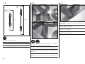
Straighten the included pull-pull cable and cut it in half with side cutters.
Ziehen Sie die im Lieferumfang enthaltenen Kabel stramm und schneiden
diese in zwei gleich lange Hälften.
Tendez le câble inclus et coupez-le en 2 à l’aide d’une pince coupante.
Raddrizzare il cavetto fornito e tagliarlo a metà con un tronchesino.
1
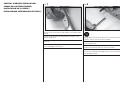
Pull the cable through the crimp sleeve and the threaded cable end. Feed
the cable through the sleeve.
Führen Sie das Kabel durch die Quetschhülse und durch den
Augenbolzen, danach wieder durch die Hülse.
Glissez le câble dans le tube laiton et dans l’oeillet. Repassez le câble
dans le tube laiton.
Inserire il cavetto nel manicotto a crimpare e nel terminale fi lettato. Far
passare di nuovo il cavo attraverso il manicotto.
2
Loop the cable back around and through the sleeve. Pull the loop taut
with minimal overhang.
Führen Sie das Kabel mit einer Schlaufe durch die Quetschhülse. Ziehen
Sie das Kabel mit minimalen Überhang stramm.
Faites une boucle avec le câble autour du tube en repassant à l’intérieur.
Tendez la boucle avec un minimum de tension.
Con il cavetto fare un anello e ripassarlo di nuovo nel manicotto. Tirare
l’anello in modo da avere la minima sporgenza.
Seite wird geladen ...
Seite wird geladen ...
Seite wird geladen ...
Seite wird geladen ...

38
2
Install the clevis assembly on the rudder horn.
Montieren Sie den Gabelkopf am Ruderhorn
Connectez la chape au guignol.
Montare tutto l’insieme della forcella sulla squadretta del timone.
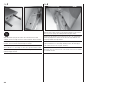
3
Use tape or some other means to hold the rudder in alignment with
the fi n. Pull the cable taut and mark the point where the cable should
pass through the threaded fi tting. Remove the clevis assembly from the
rudder horn.
Fixieren Sie das Ruder neutral ausgerichtet mit Klebeband. Ziehen Sie
das Kabel stramm und markieren die Position an der es durch den
Augenbolzen geht. Nehmen Sie den Gabelkopf wieder vom Ruderhorn ab.
Utilisez du ruban adhésif pour maintenir la gouverne alignée à la
partie fi xe de la dérive. Tendez le câble et effectuez une marque à
l’emplacement où le câble doit passer dans l’oeillet. Retirez la chape du
guignol.
Usare del nastro adesivo o qualche altro mezzo per tenere il timone
allineato con il direzionale. Tendere il cavo e segnare il punto dove il cavo
dovrebbe passare attraverso il terminale fi lettato. Togliere l’insieme della
forcella dalla squadretta del timone.
4
Using the mark on the cable as a guide for the fi nished length, follow
the procedure shown in steps 1–3 of the “Pull-Pull Cable Preparation”
section to complete the cable assembly. Attach the fi nished cable and
clevis assembly to the rudder horn.
Nehmen Sie die Markierung als Orientierung für die benötigte Länge und
folgen den Schritten 1 - 3 der Pull-Pull Kabel Vorbereitung um das Kabel
anzuschließen. Schließen Sie das fertige Kabel und den Gabelkopf am
Ruderhorn an.
Utilisez la marque sur le câble comme guide pour la longueur fi nie,
suivez la procédure de l’étape 1 à 3 de la section “Préparation du câble
aller-retour” pour terminer l’assemblage des câbles. Re-connectez les
chapes au guignol.
Usare il segno fatto sul cavo come guida per avere la lunghezza
fi nale, seguendo la procedura vista nei passi da 1 a 3 nella sezione
“Preparazione del cavetto pull-pull”. Attaccare alla squadretta del timone
il cavo terminato con le forcelle.
Seite wird geladen ...

40
2
Install the servo with the self-tapping screws, bushings, and grommets
included with the servo. Center the output shaft and install the servo
arm.
Befestigen Sie das Servo mit den selbstschneidenen Schrauben,
Gummitüllen und Messinghüllen aus dem Lieferumfang des Servos.
Zentrieren Sie das Servo und setzen den Arm auf.
Installez le servo en utilisant les vis auto-taraudeuses et les silent-blocs
fournis avec ce servo. Mettez le servo au neutre et installez son bras.
Installare il servo con le viti autofi lettanti, le boccole e i gommini forniti
con i servi. Centrare l’albero di uscita e installare la squadretta del
servo.
3
Thread the clevis and nut onto the pre-bent tow release pushrod as
shown above.
Drehen Sie den Gabelkopf und die Mutter auf den vorgebogenen Draht
wie abgebildet.
Vissez l’écrou et la chape sur la tringlerie comme sur l’illustration ci-
dessus.
Avvitare la forcella e il dado sulla barretta già piegata per il gancio di
traino.
4
Install the tow release in the pre-drilled hole and connect the clevis to
the servo.
Setzen Sie den Draht in das vorgebohrte Loch und schließen den
Gabelkopf an das Servo an.
Glissez la tringlerie dans l’orifi ce déjà percé et connectez la chape au
servo.
Installare il gancio per il traino nel suo foro e collegare la forcella al
servo.

41
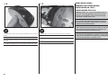
5
Ensure the tow release fully engages the front pin slot when closed and
fully retracts when open.
Stellen Sie bitte sicher dass die Schleppkupplung vollständig schließt und
öffnet.
Contrôlez que la tringlerie s’engage correctement dans la rainure avant
en position verrouillée et que la tringlerie libère totalement l’ouverture en
position relâchée.
Accertarsi che il gancio impegni bene la fessura del perno frontale
quando è chiuso e completamente retratto quando è aperto.
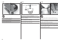
ELECTRONICS INSTALLATION/
EINBAU DER ELEKTRONIK/
INSTALLATION DE L’ÉLECTRONIQUE/
INSTALLAZIONE DELL’ELETTRONICA/
1
Attach a piece of hook and loop tape (included) to the receiver. Plug the
extensions for the fl aps and ailerons into the receiver.
Kleben Sie ein Stück Klettband aus dem Lieferumfang an den Empfänger.
Stecken Sie die Servokabelverlängerungen für Klappen und Querruder an
den Empfänger.
Collez un morceau de bande auto-agrippante (fournie) au dos du
récepteur. Connectez les rallonges de servos d’ailerons et de volets.
Attaccare al ricevitore un pezzo di nastro a strappo (incluso). Collegare
al ricevitore le prolunghe provenienti dai fl aps e dagli alettoni.
Engaged/
Geschlossen/
Verrouillé/
Bloccato/
Retracted/
Offen/
Relâché/
Retratto/

42
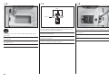
2
Mount the switch to the fuselage side at a convenient location where you
will have easy access to turn the model on and off and a clear path for
routing wiring.
Montieren Sie den Ein- und Ausschalter an einer gut zu erreichenden
Stelle an der Rumpfseite. Berücksichtigen Sie auch die Kabelführung.
Installez l’interrupteur sur un côté du fuselage à un emplacement facile
d’accès et où les câbles pourront être maintenus.
Montare l’interruttore su di un fi anco della fusoliera in una posizione che
sia facilmente raggiungibile e si possa fare un cablaggio ordinato.
3
Temporarily install the battery on the fl oor of the fuselage at the nose.
Montieren Sie vorübergehend den Akku auf dem Rumpfboden im Bug.
Installez temporairement la batterie sur la platine au niveau du nez dans
le fuselage.
Sistemare temporaneamente la batteria nella parte anteriore della
fusoliera.
4
Install the receiver in a location that provides easy wire routing.
Montieren Sie den Empfänger an einer Stelle den Sie mit dem Servokabel
einfach erreichen können.
Installez le récepteur à un emplacement où les câbles pourront être
facilement guidés.
Installare il ricevitore in una posizione dove si possa fare un cablaggio
ordinato.
Seite wird geladen ...
Seite wird geladen ...
Seite wird geladen ...
Seite wird geladen ...
Seite wird geladen ...
Seite wird geladen ...
Seite wird geladen ...
Seite wird geladen ...
Seite wird geladen ...
Seite wird geladen ...
Seite wird geladen ...
Seite wird geladen ...
Seite wird geladen ...
Seite wird geladen ...
Seite wird geladen ...
Seite wird geladen ...
Seite wird geladen ...
Seite wird geladen ...
-
 1
1
-
 2
2
-
 3
3
-
 4
4
-
 5
5
-
 6
6
-
 7
7
-
 8
8
-
 9
9
-
 10
10
-
 11
11
-
 12
12
-
 13
13
-
 14
14
-
 15
15
-
 16
16
-
 17
17
-
 18
18
-
 19
19
-
 20
20
-
 21
21
-
 22
22
-
 23
23
-
 24
24
-
 25
25
-
 26
26
-
 27
27
-
 28
28
-
 29
29
-
 30
30
-
 31
31
-
 32
32
-
 33
33
-
 34
34
-
 35
35
-
 36
36
-
 37
37
-
 38
38
-
 39
39
-
 40
40
-
 41
41
-
 42
42
-
 43
43
-
 44
44
-
 45
45
-
 46
46
-
 47
47
-
 48
48
-
 49
49
-
 50
50
-
 51
51
-
 52
52
-
 53
53
-
 54
54
-
 55
55
-
 56
56
-
 57
57
-
 58
58
-
 59
59
-
 60
60


E-flite L-13 Blanik 4.2m Benutzerhandbuch
- Kategorie
- Ferngesteuertes Spielzeug
- Typ
- Benutzerhandbuch
in anderen Sprachen
- English: E-flite L-13 Blanik 4.2m User manual
- français: E-flite L-13 Blanik 4.2m Manuel utilisateur
- italiano: E-flite L-13 Blanik 4.2m Manuale utente
Verwandte Artikel
-
E-flite Carbon-Z Cub Benutzerhandbuch
-
E-flite Extra 330SC BP Benutzerhandbuch
-
-
-
-
-
-
-
Andere Dokumente
-
Hangar 9 33cc Bedienungsanleitung
-
Blade Red Bull BO-105 CB 130X BNF Benutzerhandbuch
-
Spektrum DX8 DSMX Transmitter Only MD2 Benutzerhandbuch
-
-
3M Cold Shrink Coax Sealing Kit 98-KC 8 Bedienungsanleitung
-
MULTIPLEX Contestbericht Stoerklappe Bedienungsanleitung
-
ECO-WORTHY Adjustable Multi-Piece Solar Panel Mounting Brackets Benutzerhandbuch