
www.pahlen.com
Pahléns Fabriker AB, Box 728, SE-194 27 Upplands Väsby, Sweden
Tel. +46 (0)8 594 110 50, Fax +46 (0)8 590 868 80, e-mail: [email protected], www.pahlen.com
PANNA
P1
ELK
EXP VST VSR VST
ELK
EXP
VSR
P2
KV
AAV1
P1
M10365-0
®
Elpatron med 3-polig kombinerad termostat
och överhettningsskydd art.nr 128461
Monteringsanvisning
MA45-08S
2008
För elvärmare i värmeinstallationer
Elpatronen får endast monteras i pannor eller kärl, som från fabrik är förberedda för elpatron. Elpatron och ledningar skall
monteras så att de ej skadas av värme från eldstaden vid eldning med fasta eller ytande bränslen. Elmontering får endast ske av
behörig elinstallatör. Elpatronen får endast anslutas till s.k. öppet system med expansionstank eller slutet system, där säkerhets-
ventil är installerad.
1. Skruva in elpatronen i pannan och kontrollera att packningen kommer rätt.
2. Fyll vatten i systemet och kontrollera att det är tätt.
3. Montera kopplingsboxens underdel på elpatronen med medföljande låsring.
4. Stick ner termostatens känselkroppar i elpatronens dykrör tills kapillärrörets skyddsslang möter dykröret.
Obs! Känselkropparnas förbindelse till termostaten (kapillärrör) är ett tunnt vätskefyllt rör och skall hanteras mycket varsamt.
Om något av rören bryts eller går av måste hela termostaten bytas ut.
5. Utför elkoppling enligt kopplingsschema. (Skall ske av behörig elinstallatör).
6. Montera locket på kopplingsboxen och temperaturratten samt prova reglerfunktionen.
7. Vid överhettning löser överhettningsskyddet ut. Kontrollera orsaken och återställ genom att lossa locket och tryck in åter-
ställningsknappen på termostaten.
8. Elpatronen är avsedd för fast installation och skall alltid föregås av termostat, överhettningsskydd och allpolig brytare.
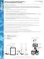
Elvärmaren skall alltid monteras i horisontellt läge med tilloppsanslutningen uppåt för att kunna evakuera ev luft. (Se skiss).
Cirkulationspumpen skall alltid monteras på returledningen och trycka vattnet genom elvärmaren.
Expansionskärl med säkerhetsventil max 6 bar skall installeras i anläggningen med oavstängbar förbindelse till elvärmaren.
Innan värmaren sätts i drift skall hela systemet vara helt fyllt med vatten och avluftas.
Elvärmaren får inte stängas in med avstängningsventiler.
Säkerhetsventilen skall motioneras 4-5 ggr/år för att upprätthålla säkerhetsfunktionen.
Om värmaren skall stängas av och frysrisk föreligger, skall hela systemet tömmas på allt vatten.
Om värmaren monteras mot brännbart material skall en gips eller icke brännbar skiva placeras mellan värmare och vägg. Skivan
skall täcka 10 cm utanför värmarens yttre mått.
EXP Expansionskärl med säkerhetsventil
ELK Elkassett
P1 Cirkulationspump till elkassett
P2 Cirkulationspump till värmesystem
VST Värme tillopp
VSR Värme retur
KV Kallvatten
AV1 Avstängningsventil
Jordanslutning i kopplingsbox
Manöverbrytare
3-pol kombinerad
överhettningsskydd
och termostat
PANNA

www.pahlen.com
Pahléns Fabriker AB, Box 728, SE-194 27 Upplands Väsby, Sweden
Tel. +46 (0)8 594 110 50, Fax +46 (0)8 590 868 80, e-mail: [email protected], www.pahlen.com
PANNA
P1
ELK
EXP VST VSR VST
ELK
EXP
VSR
P2
KV
AAV1
P1
M10365-0
Heating element with three-pole combined thermostat
and overheating limit control, art. no. 128461
MA45-08E
2008
Installation instruction
For electric heaters in heating installations
The heating element must only be installed in boilers or tanks designed to be tted with a heating element. The heating element
and wiring must be installed in such a way that they are not damaged by the heat of combustion when solid or liquid fuels are
used. Electrical installation work must be done by a qualied electrician. The heating element must only be tted to a vented
system or to a an unvented system tted with a safety valve.
1. Screw the heating element into the boiler and check that the gasket is correctly seated.
2. Fill the system and check for leaks.
3. Fit the lower part of the junction box to the heating element, using the locking ring supplied.
4. Feed the thermostat sensors into the pocket in the heating element until the protective sleeve of the capillary tube comes
up against the pocket. NOTE: The capillary tube which connects the sensors to the thermostat is a thin metal tube lled
with liquid. Handle it with care. If any of the tubes breaks or snaps off, the entire thermostat must be replaced.
5. Make the electrical connections as shown in the wiring diagram. (This must be done by a qualied electrician).
6. Install the cover on the junction box, t the temperature control knob and check the control function.
7. If the water overheats, the overheating limit control will trip. Correct the fault and reset the overheating limit control by
removing the cover and pressing the reset button on the thermostat.
8. The heating element is intended to be permanently installed. It must be connected via a thermostat, an overheating limit
control and a multi-switch.
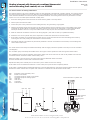
The electric heater must always be installed horizontally with the supply connection upwards so that any air can be evacuated
(see diagram).
The circulation pump must always be installed in the return pipe so that it pushes the water through the electric heater.
The installation must include an expansion vessel with a safety valve set to max 6 bar. It must not be possible to shut off the
connection between the electric heater and the safety valve.
Before the heater is put into service, the entire system must be lled with water and vented.
Do not t shutoff valves on either side of the electric heater.
Operate the safety valve manually four or ve times a year to make sure that it is working.
If the heater has to be switched off and there is a risk of frost, the system must be completely drained.
If the heater is installed against combustible material, a panel of plasterboard or some other reproof material must be placed
between the heater and the wall. The panel must extend 10 cm outside the outer dimensions of the heater.
EXP Expansion vessel with safety valve
ELK Electric in-line heater
P1 Circulation pump for electric in-line heater
P2 Circulation pump for heating system
VST Heat ow
VSR Heat return
KV Cold water
AV1 Shutoff valve
Earth connection in junction box
Operating switch
Three-pole combined
thermostat and
overheating limit
control
BOILER

www.pahlen.com
Pahléns Fabriker AB, Box 728, SE-194 27 Upplands Väsby, Sweden
Tel. +46 (0)8 594 110 50, Fax +46 (0)8 590 868 80, e-mail: [email protected], www.pahlen.com
PANNA
P1
ELK
EXP VST VSR VST
ELK
EXP
VSR
P2
KV
AAV1
P1
M10365-0
MA45-08T
2008
Installationsanweisung
Heizelement mit 3-poligem kombinierten Thermostat
und Überhitzungsschutz, Art. Nr. 128461
Für Elektroheizer in Heizungsinstallationen
Das Heizelement darf nur in Heizkesseln oder Gefässen montiert werden, die werkseitig für ein Heizelement vorbereitet sind.
Heizelement und Kabel sind so zu montieren, dass sie beim Heizen mit festen oder üssigen Brennstoffen durch die Heizquelle
keine Hitzeschäden erleidet. Der Elektroanschluss darf nur von einem dazu befugten Installateur erfolgen. Das Heizelement darf
nur an sog. offene System mit Ausgleichsbehälter angeschlossen werden oder an ein geschlossenes System, wenn dort ein Sicher-
heitsventil installiert ist.
1. Heizelement in den Kessel einschrauben und überprüfen, dass die Dichtung richtig liegt.
2. System mit Wasser befüllen und auf Dichtheit überprüfen.
3. Den unteren Teil der Anschlussbox mithilfe des mitgelieferten Sicherungsrings auf dem Heizelement montieren.
4. Die Sensoren des Thermostats in das Tauchrohr das Heizelements hinein schieben, bis der Schutzschlauch des Kapillarrohrs
das Eintauchrohr berührt. Hinweis! Die Verbindung der Sensoren mit dem Thermostat (Kapillarrohr) ist ein dünnes, mit
Flüssigkeit gefülltes Rohr, das sehr vorsichtig zu hantieren ist. Sollte eines dieser Rohre kaputt gehen oder abreissen, muss der
gesamte Thermostat ausgewechselt werden.
5. Elektroanschluss entsprechend Schaltschema vornehmen. (Muss durch einen befugten Elektroinstallateur erfolgen).
6. Deckel auf der Anschlussbox und Temperaturrad montieren sowie Reglerfunktion überprüfen.
7. Bei Überhitzung löst der Überhitzungsschutz aus. Ursache dafür überprüfen. Rückstellung durch Lösen des Deckels und
Betätigung der Rückstelltaste am Thermostat.
8. Das Heizelement ist für den festen Einbau vorgesehen, es müssen zuvor immer Thermostat, Überhitzungsschutz und all-
poliger Schalter montiert werden.
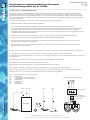
Der Elektroheizer ist immer waagerecht, mit Zulaufanschluss nach oben zu montieren, sodass Luft austreten kann (siehe Skizze).
Die Umwälzpumpe ist immer an der Rücklaueitung zu montieren und fördert Wasser durch den Elektroheizer.
Ausgleichsbehälter mit Sicherheitsventil max. 6 bar muss in der Anlage montiert sein, und zwar mit nicht abschaltbarer Verbindung
zum Elektroheizer.
Vor Inbetriebnahme des Heizers muss das gesamte System mit Wasser gefüllt und entlüftet sein.
Der Elektroheizer darf nicht mit Abschaltventilen geschlossen werden.
Sicherheitsventil 4-5 Mal/Jahr bewegen, um die Sicherheitsfunktion aufrecht zu erhalten!
Wird der Heizer abgestellt u. besteht Einfriergefahr, ist das Wasser aus dem gesamten System abzulassen!
Wird der Heizer zu brennbarem Material hin montiert, ist eine Gips- oder feuerbeständige Platte zwischen Heizer und Wand zu
montieren. Diese muss 10 cm über die äusseren Abmessungen des Heizers himweg abdecken.
EXP Ausgleichsbehälter mit Sicherheitsventil
ELK Elektroheizer
P1 Umwälzpumpe zur Elektrokassette
P2 Umwälzpumpe zum Heizungssystem
VST Wärmezulauf
VSR Wärmerücklauf
KV Kaltwasser
AV1 Abschaltventil
Masseanschluss in Anschlussbox
Betriebsschalter
3-pol. kombinierter
Überhitzungsschutz
u. Thermostat
HEIZKESSEL
-
 1
1
-
 2
2
-
 3
3


in anderen Sprachen
- English: Pahlen MA45-08 Owner's manual
- svenska: Pahlen MA45-08 Bruksanvisning
Verwandte Artikel
-
Pahlen MA45-01 Bedienungsanleitung
-
-
-
-
-
-
-
-
-