
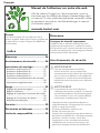
-Please read this assembly manual carefully prior to assembling this product.
- Lesen Sie sich vor der Montage des Produkts diese Montageanleitung sorgfältig durch.
- Veuillez lire attentivement le présent manuel d’assemblage avant de monter ce produit.
- Lees deze montagehandleiding zorgvuldig voordat u dit product in elkaar gaat zetten.
- Leggere attentamente questo manuale di montaggio prima di montare il prodotto.
- Antes de montar este producto, lea atentamente este manual de montaje.
- Läs den här monteringshandboken noggrant före användning av den här produkten.
- Lue tämä asennusohje huolellisesti ennen tämän tuotteen asennusta.
Attention, Achtung, Attention, Attentie, Attenzione, Atención, Giv akt, Huomio
Assembly manual
Montageanleitung
Manuel d’assemblage
Montagehandleiding
Manuale di montaggio
Manual de montaje
Monteringshandbok
Asennusohje
GET YOUR
COMPLETE
USER MANUAL
ONLINE
http://manuals.tunturi.com
WWW
IMPORTANT
FEEL BETTER EVERY DAY
www.tunturi.com
GB
DE
FR
NL
IT
ES
SV
SU
16 - 20
21 - 25
26 - 30
31 - 35
36 - 40
41 - 45
46 - 50
51 - 55
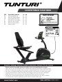
COMPETENCE F20-R BIKE


3
Competence F20-R Bike
A

F20R
106: Allen Bolt M8xP1.25x16mm (8pcs)
104: Allen Bolt M8xP1.25x60mm (4pcs)
Allen Key 5MM(1)
Allen Key 6MM(1)
Wrench *1PCS
105: Flat Washer Ø8*Ø19*2t (4pcs)
Screwdriver (1pcs)
107: Allen Bolt M8xP1.25x45mm (8pcs)
115: Flat Washer Ø8*Ø16*2t (16pcs)
i
4
Competence F20-R Bike
B

100 cm
100 cm
100 cm
100 cm
106:
Allen Bolt M8xP1.25x16mm (8pcs)
104:
Allen Bolt M8xP1.25x60mm (4pcs)
Allen Key 5MM(1)
Allen Key 6MM(1)
Wrench *1PCS
105: Flat Washer Ø8*Ø19*2t (4pcs)
Screwdriver (1pcs)
107:
Allen Bolt M8xP1.25x45mm (8pcs)
115: Flat Washer Ø8*Ø16*2t (16pcs)
5
Competence F20-R Bike
C
D

53
Allen Key 5MM(1)
Allen Bolt M8xP1.25x16mm (8pcs)
Allen Key 6MM
Screwdriver (1pcs)
Wrench *1PCS
106:
104: Allen Bolt M8xP1.25x60mm (4pcs)
107: Allen Bolt M8xP1.25x45mm (8pcs)
105: Flat Washer Ø8*Ø19*2t (4pcs)
115: Flat Washer Ø8*Ø16*2t (16pcs)
6
Competence F20-R Bike
D-1

Allen Key 5MM(1)
Allen Bolt M8xP1.25x16mm (8pcs)
Allen Key 6MM
Screwdriver (1pcs)
Wrench *1PCS
106:
104: Allen Bolt M8xP1.25x60mm (4pcs)
107: Allen Bolt M8xP1.25x45mm (8pcs)
105: Flat Washer Ø8*Ø19*2t (4pcs)
115: Flat Washer Ø8*Ø16*2t (16pcs)
7
Competence F20-R Bike
D-2

Scan to see YouTube tutorial
LLeft hand crank
Make sure to use Left hand pedal
L
RRight hand crank
Make sure to use Right hand pedal
R
Allen Key 5MM(1)
Allen Bolt M8xP1.25x16mm (8pcs)
Allen Key 6MM
Screwdriver (1pcs)
Wrench *1PCS
106:
104: Allen Bolt M8xP1.25x60mm (4pcs)
107: Allen Bolt M8xP1.25x45mm (8pcs)
105: Flat Washer Ø8*Ø19*2t (4pcs)
115: Flat Washer Ø8*Ø16*2t (16pcs)
8
Competence F20-R Bike
D-3

Scan to see
YouTube tutorial
MIN
Allen Key 5MM(1)
Allen Bolt M8xP1.25x16mm (8pcs)
Allen Key 6MM
Screwdriver (1pcs)
Wrench *1PCS
106:
104: Allen Bolt M8xP1.25x60mm (4pcs)
107: Allen Bolt M8xP1.25x45mm (8pcs)
105: Flat Washer Ø8*Ø19*2t (4pcs)
115: Flat Washer Ø8*Ø16*2t (16pcs)
9
Competence F20-R Bike
D-4

A-1
A-1
A-1
A-2
A-2
A-1 A-2
Allen Key 5MM(1)
Allen Bolt M8xP1.25x16mm (8pcs)
Allen Key 6MM
Screwdriver (1pcs)
Wrench *1PCS
106:
104: Allen Bolt M8xP1.25x60mm (4pcs)
107: Allen Bolt M8xP1.25x45mm (8pcs)
105: Flat Washer Ø8*Ø19*2t (4pcs)
115: Flat Washer Ø8*Ø16*2t (16pcs)
10
Competence F20-R Bike
D-5

Allen Key 5MM(1)
Allen Bolt M8xP1.25x16mm (8pcs)
Allen Key 6MM
Screwdriver (1pcs)
Wrench *1PCS
106:
104: Allen Bolt M8xP1.25x60mm (4pcs)
107: Allen Bolt M8xP1.25x45mm (8pcs)
105: Flat Washer Ø8*Ø19*2t (4pcs)
115: Flat Washer Ø8*Ø16*2t (16pcs)
11
Competence F20-R Bike
D-6

Allen Key 5MM(1)
Allen Bolt M8xP1.25x16mm (8pcs)
Allen Key 6MM
Screwdriver (1pcs)
Wrench *1PCS
106:
104:
Allen Bolt M8xP1.25x60mm (4pcs)
107:
Allen Bolt M8xP1.25x45mm (8pcs)
105: Flat Washer Ø8*Ø19*2t (4pcs)
115: Flat Washer Ø8*Ø16*2t (16pcs)
12
Competence F20-R Bike
D-7

Allen Key 5MM(1)
Allen Bolt M8xP1.25x16mm (8pcs)
Allen Key 6MM
Screwdriver (1pcs)
Wrench *1PCS
106:
104:
Allen Bolt M8xP1.25x60mm (4pcs)
107:
Allen Bolt M8xP1.25x45mm (8pcs)
105: Flat Washer Ø8*Ø19*2t (4pcs)
115: Flat Washer Ø8*Ø16*2t (16pcs)
13
Competence F20-R Bike
D-8

Allen Key 5MM(1)
Allen Bolt M8xP1.25x16mm (8pcs)
Allen Key 6MM
Screwdriver (1pcs)
Wrench *1PCS
106:
104:
Allen Bolt M8xP1.25x60mm (4pcs)
107:
Allen Bolt M8xP1.25x45mm (8pcs)
105: Flat Washer Ø8*Ø19*2t (4pcs)
115: Flat Washer Ø8*Ø16*2t (16pcs)
Preassembled
Vormontiert
Pré assemblé
Voorgemonteerd
Pre-assemblato
Pre ensamblado
Förmonterad
Esikoottu
14
Competence F20-R Bike
D-9

+
_
+
_
AA
AA
15
Competence F20-R Bike
E-1

16
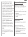
USER MANUAL ON OUR WEBSITE
To reduce the impact on the environment,
you will only find the assembly steps in this manual.
To learn how to use and maintain this product,
please download the user manual from:
English
manuals.tunturi.com
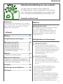
Welcome
Important Safety Instructions
This manual is an essential part of your training
equipment please read all instructions in this
manual before you start using this equipment. The
following precautions must always be followed:
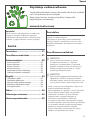
Index
Welcome ����������������������������������������� 16
Safety warnings ������������������������������ 16
Assembly instructions ��������������������� 17
Description illustration A ������������������������������17
Description illustration B ������������������������������17
Description illustration C ������������������������������17
Description illustration D ������������������������������17
Additional assembly information� ���������������17
Additional information ���������������������������������18
Use�������������������������������������������������� 18
Adjusting the support feet ���������������������������18
Adjusting resistance �������������������������������������19
Adjusting the horizontal seat position ���������19
Adjusting the backrest inclination ����������������19
Replacing the batteries ��������������������������������19
Warranty ����������������������������������������� 19
Declaration of the manufacturer ���� 20
Disclaimer ��������������������������������������� 20
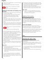
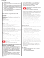
Safety warnings
⚠ WARNING
• Read the safety warnings and the
instructions. Failure to follow the safety
warnings and the instructions can cause
personal injury or damage to the equipment.
Keep the safety warnings and the instructions
for future reference.
⚠ WARNING
• Heart rate monitoring systems may be
inaccurate.
• Over exercise may result in serious injury
or death. If you feel faint stop exercising
immediately.
- The equipment is suitable for domestic
use only. The equipment is not suitable for
commercial use.
- Max. usage is limited to 3 hrs a day.
- The use of this equipment by children or
persons with a physical, sensory, mental
or motorial disability, or lack of experience
and knowledge can give cause to hazards.
Persons responsible for their safety must give
explicit instructions or supervise the use of the
equipment.
- Before starting your workout, consult a
physician to check your health.
- If you experience nausea, dizziness or other
abnormal symptoms, immediately stop your
workout and consult a physician.
- To avoid muscular pain and strain, start each
workout by warming up and finish each workout
by cooling down. Remember to stretch at the
end of the workout.
- The equipment is suitable for indoor use only.
The equipment is not suitable for outdoor use.

17
English
- Only use the equipment in environments
with adequate ventilation. Do not use the
equipment in draughty environments in order
not to catch a cold.
- Only use the equipment in environments with
ambient temperatures between 10°C~35°C/
50°F~95°F. Only store the equipment in
environments with ambient temperatures
between 5°C~45°C/ 41°F~113°F.
- Do not use or store the equipment in humid
surroundings. The air humidity must never be
more than 80%.
- Only use the equipment for its intended
purpose. Do not use the equipment for other
purposes than described in the manual.
- Do not use the equipment if any part is
damaged or defective. If a part is damaged or
defective, contact your dealer.
- Keep your hands, feet and other body parts
away from the moving parts.
- Keep your hair away from the moving parts.
- Wear appropriate clothing and shoes.
- Keep clothing, jewellery and other objects away
from the moving parts.
- Make sure that only one person uses the
equipment at a time. The equipment must not
be used by persons weighing more than 135 kg
(300 lbs).
- Do not open equipment without consulting
your dealer.
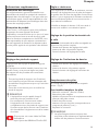
Assembly instructions
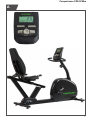
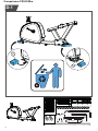
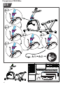
Description illustration A
The illustration shows what the trainer will looks
like after the assembly is completed.
You can use this as a reference during your
assembly, but do follow the assembly steps
always in the correct sequence as showed in the
illustrations.
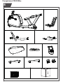
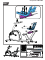
Description illustration B
The illustration shows what components and parts
you should find when un-boxing your product.
‼ NOTE
• Small parts can be hidden/ packed in hollow
spaces in the Styrofoam product protection
• If a part is missing, contact your dealer.
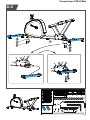
Description illustration C
The illustration shows the hardware kit that comes
with your product.
The hardware kit contains bolts, washers, screws
, nuts etc. and the required tools to properly fit
your trainer.
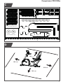
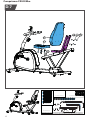
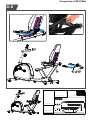
Description illustration D
The illustrations shows you in the correct following
order how to assembly your trainer best.
‼ NOTE
• Part numbers shown in the assembly steps
are commencing with the spare part drawing
that can be found in the online version user
manual.
⚠ WARNING
• Assemble the equipment in the given order.
• Carry and move the equipment with at least
two persons.
⚠ CAUTION
• Place the equipment on a firm, level surface.
• Place the equipment on a protective base to
prevent damage to the floor surface.
• Allow at least 100 cm of clearance around the
equipment.
• Refer to the illustrations for the correct
assembly of the equipment.
Additional assembly information�
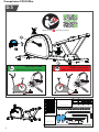
D3 How to fit the pedals correctly�
‼ NOTE
• Right and left side are determined from an
exercising positions perspective.
Right hand pedal
Find the “R” or “L” mark on the pedal axle
- Fit the right hand pedal “R” into the right hand
crank.
- Firstly turn the pedal axle in clockwise direction
by hand.
- Use the wrench to fully tighten the pedal.
Left hand pedal
- Fit the left hand pedal “L” into the left hand
crank.

18
English
- Firstly turn the pedal axle in counter-clockwise
direction by hand.
- Use the wrench to fully tighten the pedal.
Click to see our supportive YouTube
video
https://youtu.be/Devel2ZhCAc
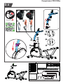
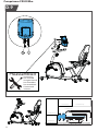
Additional information to Assembly step
D4 & D5
- Set the tension adjustment knob to the lowest
(1) tension setting level.
- Connect the sensor wire cable (black plastic
connectors), taking note of the correct
orientation so the locking system will be
effective.
- Hook up the steel cable rod end coming from
the bottom of the upright tube onto the hook
from the steel cable coming from the main
frame.
- Pull the outer steel cable from the upright tube
cable and fit the brass ending into the bracket
on the cable end coming from the main frame.
Click to see our supportive YouTube
video
https://youtu.be/nn5AnVxmPag
- Place the upright tube over the main frame
fixing bracket, in where the fixing bolts are pre-
assembled and stay pre-assembled.
( While lowering the upright tube, gently pull
the upper part of the cable up, to avoid the
cable get caught by the connection. )
- The upright tube should automatically find the
centre position, but it is advisable to make the
slightest correction needed to make sure the
position is good.
- The perfect position is when the fixing bolts are
perfectly centred in line with the upright tube
holes.
‼ NOTE
• Avoid the cable connection between these
two parts get pinched.
• By fastening the two bolts (turning in
clockwise direction) on the front side you will
widen the fixing bracket so the upright gets
fixed firmly.
- To fix the upright tube firmly it is needed to
tighten the bolt on the upper side first firmly.
- After fixing the upper bold, you need to fix the
lower bold firmly.
- By fixing the lower bold, the upright tube will
be repositioned slightly resulting that the upper
bold can be fixed a little more, therefore it is
needed to fix the upper bolt again.
- Repeat these steps until both bolts are firmly
fixed to ensure the upright tube fixation well.
‼ NOTE
• Save the tools provided with this product,
after you completed the product assembly,
for future service purposes.
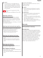
Additional information
Packaging disposal
Government guidelines ask that we reduce the
amount of waste material disposed of in land fill
sites. We therefore ask that you dispose of all
packaging waste responsibly at public recycling
centres.
End of life disposal
We at Tunturi hope you enjoy many years of
enjoyable use from your fitness trainer. However,
a time will come when your fitness trainer will
come to the end of its useful life. Under ‘European
WEEE Legislation you are responsible for the
appropriate disposal of your fitness trainer to a
recognised public collection facility.
Use
Adjusting the support feet
The equipment is equipped with adjustable
support feet.
If the equipment feels unstable, wobbly, or not
levelled well, these support feet can be adjusted
to make the required corrections.
- Turn the support feet in/ out as required to put
the equipment in a stable and as well possible
levelled position.
- Tighten the locknut’s to lock the support feet.

19
English
‼ NOTE
• The equipment is most stable when it is
as low to the floor as possible. Therefore,
start to level the equipment by turning all
support feet fully in, before turning out the
required support feet to stabilize and level
the equipment.
Click to see our supportive YouTube
video
https://youtu.be/3BiN9mc5Tmw?t=535
Adjusting resistance
To increase or decrease resistance, turn the
adjustment knob at the top of the handlebar
support tube clockwise (+ direction) to increase
resistance and counter-clockwise (- direction) to
decrease resistance.
The scale above the knob (1-8) helps you find and
set a suitable resistance.
Adjusting the horizontal seat position
The horizontal seat position can be adjusted by
setting the seat to the required position.
- Loosen the seat adjustment knob.
- Move the seat to the required position.
- Tighten the seat adjustment knob.
Adjusting the backrest inclination
- Loosen the backrest inclination adjustment
knob.
- Move the backrest to the required position.
- Tighten the backrest inclination adjustment
knob.
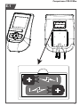
Replacing the batteries
The console is equipped with 2 AA batteries at
the rear of the console. (Fig. E)
To fit/ Replace the batteries
- Remove the cover. (Located on the back side).
- Remove the old batteries.
Only valid when replacing the batteries for fresh
ones.
- Insert the new batteries.
Make sure that batteries match the (+) and (-)
polarity markings.
- Mount the cover.
‼ NOTE
• Empty batteries should always be recycled
per your Local legal regulations to save the
environment.
⚠ WARNING
• Do not expose batteries to big temperature
changes to prevent the batteries from
leaking.
• To prevent your batteries from leaking, take
them out if you plan on not using your device
for longer periods of time.
• When inserting multiple batteries into a
device, always use the same brand, the same
type, and the same energy level.
Warranty
Tunturi purchaser‘s warranty
Warranty terms
The consumer is entitled to the applicable legal
rights stated in the national legislation concerning
the commerce of consumer goods. This warranty
does not restrict these rights. The Purchaser’s
Warranty is only valid if the item is used in an
environment approved by Tunturi New Fitness BV,
and is maintained as instructed for that particular
equipment. The product-specific approved
environment and maintenance instructions are
stated in the “user manual” of the product. The
“user manual” can be downloaded from our
website. http://manuals.tunturi.com

20
English
Declaration of the manufacturer
Tunturi New Fitness BV declares that the product
is in conformity with the following standards
and directives: EN 957 (HC), 2014/30/EU . The
product therefore carries the CE label.
04-2020
Tunturi New Fitness BV
Purmerweg 1
1311 XE Almere
The Netherlands
Disclaimer
© 2020 Tunturi New Fitness BV
All rights reserved.
- The product and the manual are subject to
change.
- Specifications can be changed without further
notice.
- Check our website for the latest user manual
version.
Seite wird geladen ...
Seite wird geladen ...
Seite wird geladen ...
Seite wird geladen ...
Seite wird geladen ...
Seite wird geladen ...
Seite wird geladen ...
Seite wird geladen ...
Seite wird geladen ...
Seite wird geladen ...
Seite wird geladen ...
Seite wird geladen ...
Seite wird geladen ...
Seite wird geladen ...
Seite wird geladen ...
Seite wird geladen ...
Seite wird geladen ...
Seite wird geladen ...
Seite wird geladen ...
Seite wird geladen ...
Seite wird geladen ...
Seite wird geladen ...
Seite wird geladen ...
Seite wird geladen ...
Seite wird geladen ...
Seite wird geladen ...
Seite wird geladen ...
Seite wird geladen ...
Seite wird geladen ...
Seite wird geladen ...
Seite wird geladen ...
Seite wird geladen ...
Seite wird geladen ...
Seite wird geladen ...
Seite wird geladen ...
Seite wird geladen ...
-
 1
1
-
 2
2
-
 3
3
-
 4
4
-
 5
5
-
 6
6
-
 7
7
-
 8
8
-
 9
9
-
 10
10
-
 11
11
-
 12
12
-
 13
13
-
 14
14
-
 15
15
-
 16
16
-
 17
17
-
 18
18
-
 19
19
-
 20
20
-
 21
21
-
 22
22
-
 23
23
-
 24
24
-
 25
25
-
 26
26
-
 27
27
-
 28
28
-
 29
29
-
 30
30
-
 31
31
-
 32
32
-
 33
33
-
 34
34
-
 35
35
-
 36
36
-
 37
37
-
 38
38
-
 39
39
-
 40
40
-
 41
41
-
 42
42
-
 43
43
-
 44
44
-
 45
45
-
 46
46
-
 47
47
-
 48
48
-
 49
49
-
 50
50
-
 51
51
-
 52
52
-
 53
53
-
 54
54
-
 55
55
-
 56
56


in anderen Sprachen
- français: Tunturi F20-R
- español: Tunturi F20-R
- italiano: Tunturi F20-R
- Nederlands: Tunturi F20-R
- eesti: Tunturi F20-R
- svenska: Tunturi F20-R
