
www.tunturi.com
- Please read this assembly manual carefully prior to assembling this product.
- Lesen Sie sich vor der Montage des Produkts diese Montageanleitung sorgfältig durch.
- Veuillez lire attentivement le présent manuel d’assemblage avant de monter ce produit.
- Lees deze montagehandleiding zorgvuldig voordat u dit product in elkaar gaat zetten.
- Leggere attentamente questo manuale di montaggio prima di montare il prodotto.
- Antes de montar este producto, lea atentamente este manual de montaje.
- Läs den här monteringshandboken noggrant före användning av den här produkten.
- Lue tämä asennusohje huolellisesti ennen tämän tuotteen asennusta.
Attention, Achtung, Attention, Attentie, Attenzione, Atención, Giv akt, Huomio
GB Assembly manual
DE Montageanleitung
FR Manuel d’assemblage
NL Montagehandleiding
IT Manuale di montaggio
ES Manual de montaje
SV Monteringshandbok
SU Asennusohje
F20-R Bike Competence
EN957
Class HC
Made in China
RoHS
2011/65/EU
i
SN:
HOME USE
MAX USER WEIGHT: 135 KGS
300 LBS
INPUT:
SKU: 17TBR20000
Recumbent bike F20-R
GET YOUR
USER MANUAL
ONLINE
http://manuals.tunturi.com
WWW
IMPORTANT
16 - 19
20 - 24
25 - 29
30 - 33
34 - 37
38 - 41
42 - 45
46 - 49


3
F20-R Bike
A

F20R
106: Allen Bolt M8xP1.25x16mm (8pcs)
104: Allen Bolt M8xP1.25x60mm (4pcs)
Allen Key 5MM(1)
Allen Key 6MM(1)
Wrench *1PCS
105: Flat Washer Ø8*Ø19*2t (4pcs)
Screwdriver (1pcs)
107: Allen Bolt M8xP1.25x45mm (8pcs)
115: Flat Washer Ø8*Ø16*2t (16pcs)
i
4
F20-R Bike
B

100 cm
100 cm
100 cm
100 cm
106:
Allen Bolt M8xP1.25x16mm (8pcs)
104:
Allen Bolt M8xP1.25x60mm (4pcs)
Allen Key 5MM(1)
Allen Key 6MM(1)
Wrench *1PCS
105: Flat Washer Ø8*Ø19*2t (4pcs)
Screwdriver (1pcs)
107:
Allen Bolt M8xP1.25x45mm (8pcs)
115: Flat Washer Ø8*Ø16*2t (16pcs)
5
F20-R Bike
C
D

53
Allen Key 5MM(1)
Allen Bolt M8xP1.25x16mm (8pcs)
Allen Key 6MM
Screwdriver (1pcs)
Wrench *1PCS
106:
104: Allen Bolt M8xP1.25x60mm (4pcs)
107: Allen Bolt M8xP1.25x45mm (8pcs)
105: Flat Washer Ø8*Ø19*2t (4pcs)
115: Flat Washer Ø8*Ø16*2t (16pcs)
6
F20-R Bike
D-1

Allen Key 5MM(1)
Allen Bolt M8xP1.25x16mm (8pcs)
Allen Key 6MM
Screwdriver (1pcs)
Wrench *1PCS
106:
104: Allen Bolt M8xP1.25x60mm (4pcs)
107: Allen Bolt M8xP1.25x45mm (8pcs)
105: Flat Washer Ø8*Ø19*2t (4pcs)
115: Flat Washer Ø8*Ø16*2t (16pcs)
7
F20-R Bike
D-2

L
Left hand crank
Make sure to use Left hand pedal
L
R
Right hand crank
Make sure to use Right hand pedal
R
Allen Key 5MM(1)
Allen Bolt M8xP1.25x16mm (8pcs)
Allen Key 6MM
Screwdriver (1pcs)
Wrench *1PCS
106:
104: Allen Bolt M8xP1.25x60mm (4pcs)
107: Allen Bolt M8xP1.25x45mm (8pcs)
105: Flat Washer Ø8*Ø19*2t (4pcs)
115: Flat Washer Ø8*Ø16*2t (16pcs)
8
F20-R Bike
D-3

AB
C
DE
M
a
x
.
Allen Key 5MM(1)
Allen Bolt M8xP1.25x16mm (8pcs)
Allen Key 6MM
Screwdriver (1pcs)
Wrench *1PCS
106:
104: Allen Bolt M8xP1.25x60mm (4pcs)
107: Allen Bolt M8xP1.25x45mm (8pcs)
105: Flat Washer Ø8*Ø19*2t (4pcs)
115: Flat Washer Ø8*Ø16*2t (16pcs)
9
F20-R Bike
D-4

A-1
A-1
A-1
A-2
A-2
A-1 A-2
Allen Key 5MM(1)
Allen Bolt M8xP1.25x16mm (8pcs)
Allen Key 6MM
Screwdriver (1pcs)
Wrench *1PCS
106:
104: Allen Bolt M8xP1.25x60mm (4pcs)
107: Allen Bolt M8xP1.25x45mm (8pcs)
105: Flat Washer Ø8*Ø19*2t (4pcs)
115: Flat Washer Ø8*Ø16*2t (16pcs)
10
F20-R Bike
D-5

Allen Key 5MM(1)
Allen Bolt M8xP1.25x16mm (8pcs)
Allen Key 6MM
Screwdriver (1pcs)
Wrench *1PCS
106:
104: Allen Bolt M8xP1.25x60mm (4pcs)
107: Allen Bolt M8xP1.25x45mm (8pcs)
105: Flat Washer Ø8*Ø19*2t (4pcs)
115: Flat Washer Ø8*Ø16*2t (16pcs)
11
F20-R Bike
D-6

Allen Key 5MM(1)
Allen Bolt M8xP1.25x16mm (8pcs)
Allen Key 6MM
Screwdriver (1pcs)
Wrench *1PCS
106:
104:
Allen Bolt M8xP1.25x60mm (4pcs)
107:
Allen Bolt M8xP1.25x45mm (8pcs)
105: Flat Washer Ø8*Ø19*2t (4pcs)
115: Flat Washer Ø8*Ø16*2t (16pcs)
12
F20-R Bike
D-7

Allen Key 5MM(1)
Allen Bolt M8xP1.25x16mm (8pcs)
Allen Key 6MM
Screwdriver (1pcs)
Wrench *1PCS
106:
104:
Allen Bolt M8xP1.25x60mm (4pcs)
107:
Allen Bolt M8xP1.25x45mm (8pcs)
105: Flat Washer Ø8*Ø19*2t (4pcs)
115: Flat Washer Ø8*Ø16*2t (16pcs)
13
F20-R Bike
D-8

Allen Key 5MM(1)
Allen Bolt M8xP1.25x16mm (8pcs)
Allen Key 6MM
Screwdriver (1pcs)
Wrench *1PCS
106:
104:
Allen Bolt M8xP1.25x60mm (4pcs)
107:
Allen Bolt M8xP1.25x45mm (8pcs)
105: Flat Washer Ø8*Ø19*2t (4pcs)
115: Flat Washer Ø8*Ø16*2t (16pcs)
Preassembled
Vormontiert
Pré assemblé
Voorgemonteerd
Pre-assemblato
Pre ensamblado
Förmonterad
Esikoottu
14
F20-R Bike
D-9

+
_
+
_
AA
AA
15
F20-R Bike
E-1

16
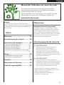
USER MANUAL ON OUR WEBSITE
To reduce the impact on the environment, you will only
find the assembly steps in this manual.
To learn how to use this product, please download the
user manual from:
manuals.tunturi.com
English
Welcome
Important Safety Instructions
This Owner’s Manual is an essential part of your
training equipment: reading all instructions in this
manual before you start using this appliance. The
following precautions must always be followed:
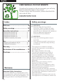
Index
Welcome ����������������������������������������� 16
Safety warnings ������������������������������ 16
Assembly instructions ��������������������� 17
Description illustration A ������������������������������17
Description illustration B ������������������������������17
Description illustration C ������������������������������17
Description illustration D ������������������������������17
Additional assembly information� ���������������17
Use�������������������������������������������������� 18
Replacing the batteries (Fig� E) ��������������������18
Additional information ���������������������������������19
Warranty ����������������������������������������� 19
Declaration of the manufacturer ���� 19
Disclaimer ��������������������������������������� 19
Safety warnings
⚠ WARNING
• Read the safety warnings and the
instructions. Failure to follow the safety
warnings and the instructions can cause
personal injury or damage to the equipment.
Keep the safety warnings and the
instructions for future reference.
⚠ WARNING
• Heart rate monitoring systems may be
inaccurate.
• Over exercise may result in serious injury
or death. If you feel faint stop exercising
immediately.
- The equipment is suitable for domestic
use only. The equipment is not suitable for
commercial use.
- Max. usage is limited to 3 hrs a day.
- The use of this equipment by children or
persons with a physical, sensory, mental
or motorial disability, or lack of experience
and knowledge can give cause to hazards.
Persons responsible for their safety must give
explicit instructions or supervise the use of the
equipment.
- Before starting your workout, consult a
physician to check your health.
- If you experience nausea, dizziness or other
abnormal symptoms, immediately stop your
workout and consult a physician.
- To avoid muscular pain and strain, start each
workout by warming up and finish each workout
by cooling down. Remember to stretch at the
end of the workout.
- The equipment is suitable for indoor use only.
The equipment is not suitable for outdoor use.

17
English
- Only use the equipment in environments
with adequate ventilation. Do not use the
equipment in draughty environments in order
not to catch a cold.
- Only use the equipment in environments with
ambient temperatures between 10°C~35°C/
50°F~95°F. Only store the equipment in
environments with ambient temperatures
between 5°C~45°C/ 41°F~113°F.
- Do not use or store the equipment in humid
surroundings. The air humidity must never be
more than 80%.
- Only use the equipment for its intended
purpose. Do not use the equipment for other
purposes than described in the manual.
- Do not use the equipment if any part is
damaged or defective. If a part is damaged or
defective, contact your dealer.
- Keep your hands, feet and other body parts
away from the moving parts.
- Keep your hair away from the moving parts.
- Wear appropriate clothing and shoes.
- Keep clothing, jewellery and other objects away
from the moving parts.
- Make sure that only one person uses the
equipment at a time. The equipment must not
be used by persons weighing more than 135 kg
(300 lbs).
- Do not open equipment without consulting
your dealer.
Assembly instructions
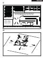
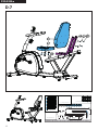
Description illustration A
The illustration shows what the trainer will looks
like after the assembly is completed.
You can use this as a reference during your
assembly, but do follow the assembly steps
always in the correct sequence as showed in the
illustrations.
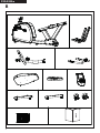
Description illustration B
The illustration shows what components and parts
you should find when un-boxing your product.
‼ NOTE
• Small parts can be hidden/ packed in hollow
spaces in the Styrofoam product protection
• If a part is missing, contact your dealer.
Description illustration C
The illustration shows the hardware kit that comes
with your product.
The hardware kit contains bolts, washers, screws
, nuts etc. and the required tools to properly fit
your trainer.
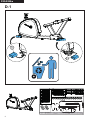
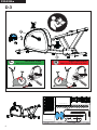
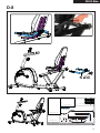
Description illustration D
The illustrations shows you in the correct following
order how to assembly your trainer best.
‼ NOTE
• Part numbers shown in the assembly steps
are commencing with the spare part drawing
that can be found in the online version user
manual.
⚠ WARNING
• Assemble the equipment in the given order.
• Carry and move the equipment with at least
two persons.
⚠ CAUTION
• Place the equipment on a firm, level surface.
• Place the equipment on a protective base to
prevent damage to the floor surface.
• Allow at least 100 cm of clearance around
the equipment.
• Refer to the illustrations for the correct
assembly of the equipment.
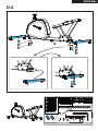
Additional assembly information�
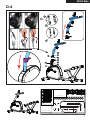
D3 How to fit the pedals correctly�
‼ NOTE
• Right and left side are determined from an
exercising positions perspective.
Right hand pedal
Find the “R” or “L” mark on the pedal axle
- Fit the right hand pedal “R” into the right hand
crank.
- Firstly turn the pedal axle in clockwise direction
by hand.
- Use the wrench to fully tighten the pedal.
Left hand pedal
- Fit the left hand pedal “L” into the left hand
crank.

18
English
- Firstly turn the pedal axle in counter-clockwise
direction by hand.
- Use the wrench to fully tighten the pedal.
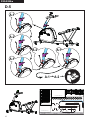
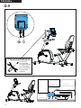
Additional information to Assembly step
D5
- Establish the wire connection between the
cable coming from the main frame, and the
lower part of the cable pre fitted in the upright
tube.
- Place the upright tube over the main frame
fixing bracket, in where the fixing bolts are pre-
assembled and stay pre-assembled.
( While lowering the upright tube, gently pull
the upper part of the cable up, to avoid the
cable get caught by the connection. )
- The upright tube should automatically find the
centre position, but it is advisable to make the
slightest correction needed to make sure the
position is good.
- The perfect position is when the fixing bolts are
perfectly centred in line with the upright tube
holes.
‼ NOTE
• Avoid the cable connection between these
two parts get pinched.
• By fastening the two bolts (turning in
clockwise direction) on the front side you will
widen the fixing bracket so the upright gets
fixed firmly.
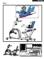
- To fix the upright tube firmly it is needed to
tighten the bolt on the upper side first firmly.
- After fixing the upper bold, you need to fix the
lower bold firmly.
- By fixing the lower bold, the upright tube will
be repositioned slightly resulting that the upper
bold can be fixed a little more, therefore it is
needed to fix the upper bolt again.
- Repeat these steps until both bolts are firmly
fixed to ensure the upright tube fixation well.
‼ NOTE
• Save the tools provided with this product,
after you completed the product assembly,
for future service purposes.
Use
Adjusting the support feet
The equipment is equipped with 5 support feet. If
the equipment is not stable, the support feet can
be adjusted.
- Turn the support feet as required to put the
equipment in a stable position.
- Tighten the locknuts to lock the support feet.
‼ NOTE
• The machine is the most stable when all
support feet are turned fully in. Therefore
start to level the machine by turning all
support feet fully in, before turning out the
required support feet to stable the machine.
Adjusting resistance
To increase or decrease resistance, turn the
adjustment knob at the top of the handlebar
support tube clockwise (+ direction) to increase
resistance and counter-clockwise (- direction) to
decrease resistance.
The scale above the knob (1-8) helps you find and
set a suitable resistance.
Adjusting the horizontal seat position
The horizontal seat position can be adjusted by
setting the seat to the required position.
- Loosen the seat adjustment knob.
- Move the seat to the required position.
- Tighten the seat adjustment knob.
Adjusting the backrest inclination
- Loosen the backrest inclination adjustment
knob.
- Move the backrest to the required position.
- Tighten the backrest inclination adjustment
knob.
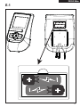
Replacing the batteries (Fig� E)
The console is equipped with 2 AA batteries at
the rear of the console.
- Remove the cover.
- Remove the old batteries.
- Insert the new batteries. Make sure that
batteries match the (+) and (-) polarity markings.
- Mount the cover.

19
English
Additional information
Packaging disposal
Government guidelines ask that we reduce the
amount of waste material disposed of in land fill
sites. We therefore ask that you dispose of all
packaging waste responsibly at public recycling
centres.
End of life disposal
We at Tunturi hope you enjoy many years of
enjoyable use from your fitness trainer. However,
a time will come when your fitness trainer will
come to the end of its useful life. Under ‘European
WEEE Legislation you are responsible for the
appropriate disposal of your fitness trainer to a
recognised public collection facility.
Warranty
Tunturi purchaser‘s warranty
Warranty terms
The consumer is entitled to the applicable legal
rights stated in the national legislation concerning
the commerce of consumer goods. This warranty
does not restrict these rights. The Purchaser’s
Warranty is only valid if the item is used in an
environment approved by Tunturi New Fitness BV
for that particular equipment. The product-specific
approved environment is stated in the Owner’s
Manual provided with your equipment.
Declaration of the manufac-
turer
Tunturi New Fitness BV declares that the product
is in conformity with the following standards
and directives: EN 957 (HC), 2014/30/EU . The
product therefore carries the CE label.
04-2020
Tunturi New Fitness BV
Purmerweg 1
1311 XE Almere
The Netherlands
Disclaimer
© 2020 Tunturi New Fitness BV
All rights reserved.
- The product and the manual are subject to
change.
- Specifications can be changed without further
notice.
- Check our website for the latest user manual
version.

20
Deutsch
Deutsch
Diese deutsche Bedienungsanleitung ist eine
Übersetzung des englischen Textes. Es können
keine Rechte auf diese Übersetzung abgeleitet
werden.
Index
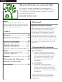
Benutzerhandbuch auf unserer Website
Um die Belastung für die Umwelt zu reduzieren, finden
Sie in dieser Anleitung nur die Montageschritte.
Um zu erfahren, wie Sie dieses Produkt verwenden, laden
Sie bitte das Benutzerhandbuch herunter:
manuals.tunturi.com
Willkommen
Wichtige sicherheitshinweise
Dieses Handbuch ist ein wesentlicher Bestandteil
Ihres Trainingsgerätes. Lesen Sie es bitte
sorgfältig durch, bevor Sie Ihr Trainingsgerät
montieren, mit ihm trainieren oder es warten.
Bitte bewahren Sie dieses Handbuch auf; es wird
Sie jetzt und zukünftig darüber informieren, wie
Sie Ihr Gerät benutzen und warten. Befolgen Sie
diese Anweisungen immer sorgfältig.
Warnhinweise zur Sicherheit
⚠ WARNUNG
• Lesen Sie die Warnhinweise zur Sicherheit
und die Anweisungen. Werden die
Warnhinweise zur Sicherheit und die
Anweisungen nicht befolgt, kann dies
zu Personenverletzungen und Schäden
am Gerät führen. Bewahren Sie die
Warnhinweise zur Sicherheit und die
Anweisungen zur künftigen Bezugnahme
auf.
⚠ WARNUNG
• Herzfrequenz-Überwachungssysteme
können ungenau sein.
• Eine Überanstrengung kann zu schweren
Schädigungen oder zum Tod führen. Wenn
Sie sich schwach oder ohnmächtig fühlen,
stellen Sie die Übungen unverzüglich ein.
- Das Gerät ist nur für den Hausgebrauch
geeignet. Das Gerät ist nicht für den
gewerblichen Gebrauch geeignet.
- Die maximale Verwendung ist auf 3 Stunden
pro Tag beschränkt
Willkommen ������������������������������������ 20
Warnhinweise zur Sicherheit ���������� 20
Montageanleitungen ���������������������� 21
Beschreibung Abbildung A ��������������������������21
Beschreibung Abbildung B ���������������������������21
Beschreibung Abbildung C ��������������������������21
Beschreibung Abbildung D ��������������������������21
Zusätzliche Montagehinweise ���������������������22
Gebrauch ���������������������������������������� 23
Erneuerung der Batterien (Fig E ) ����������������23
Zusätzliche Informationen ����������������������������23
Garantie ������������������������������������������ 23
Herstellererklärung ������������������������ 24
Haftungsausschluss ������������������������� 24
Seite wird geladen ...
Seite wird geladen ...
Seite wird geladen ...
Seite wird geladen ...
Seite wird geladen ...
Seite wird geladen ...
Seite wird geladen ...
Seite wird geladen ...
Seite wird geladen ...
Seite wird geladen ...
Seite wird geladen ...
Seite wird geladen ...
Seite wird geladen ...
Seite wird geladen ...
Seite wird geladen ...
Seite wird geladen ...
Seite wird geladen ...
Seite wird geladen ...
Seite wird geladen ...
Seite wird geladen ...
Seite wird geladen ...
Seite wird geladen ...
Seite wird geladen ...
Seite wird geladen ...
Seite wird geladen ...
Seite wird geladen ...
Seite wird geladen ...
Seite wird geladen ...
Seite wird geladen ...
Seite wird geladen ...
Seite wird geladen ...
Seite wird geladen ...
-
 1
1
-
 2
2
-
 3
3
-
 4
4
-
 5
5
-
 6
6
-
 7
7
-
 8
8
-
 9
9
-
 10
10
-
 11
11
-
 12
12
-
 13
13
-
 14
14
-
 15
15
-
 16
16
-
 17
17
-
 18
18
-
 19
19
-
 20
20
-
 21
21
-
 22
22
-
 23
23
-
 24
24
-
 25
25
-
 26
26
-
 27
27
-
 28
28
-
 29
29
-
 30
30
-
 31
31
-
 32
32
-
 33
33
-
 34
34
-
 35
35
-
 36
36
-
 37
37
-
 38
38
-
 39
39
-
 40
40
-
 41
41
-
 42
42
-
 43
43
-
 44
44
-
 45
45
-
 46
46
-
 47
47
-
 48
48
-
 49
49
-
 50
50
-
 51
51
-
 52
52


in anderen Sprachen
- English: Tunturi F20-R
- français: Tunturi F20-R
- español: Tunturi F20-R
- italiano: Tunturi F20-R
- Nederlands: Tunturi F20-R
- svenska: Tunturi F20-R
- suomi: Tunturi F20-R
Verwandte Artikel
-
Tunturi F20-R Manual Concise
-
-
-
-
-
-
Tunturi F20 Manual Concise
-
Tunturi E60R Benutzerhandbuch
-
-


