Danfoss CF-RD Room Thermostat Installationsanleitung
- Kategorie
- Thermostate
- Typ
- Installationsanleitung

088U0212
Instructions CF-RD Room Thermostat with Display
Instruktion CF-RD Raum Thermostat mit Display
Vejledning CF-RD Rumtermostat med display
Instruction CF-RD Thermostat avec écran
Bruksanvisning till CF-RD rumstermostat med display
SE

1VI.UH.Q3.80
Produced by Danfoss Floor Heating Hydronics 01.2006
Instruction CF-RD Room Thermostat with Display
Instruction . . . . . . . . . . . . . . . . . . . . . . . 3
Instruktion . . . . . . . . . . . . . . . . . . . . . . 12
Vejledning . . . . . . . . . . . . . . . . . . . . . . 22
Instruction . . . . . . . . . . . . . . . . . . . . . . 31
SE
Bruksanvisning . . . . . . . . . . . . . . . . . . 41

2
VI.UH.Q3.80
Produced by Danfoss Floor Heating Hydronics 01.2006
Instruction CF-RD Room Thermostat with Display

3VI.UH.Q3.80
Produced by Danfoss Floor Heating Hydronics 01.2006
Instruction CF-RD Room Thermostat with Display
1. Functional Overview . . . . . . . . . . . . . . . . . . . 4
2. Installation . . . . . . . . . . . . . . . . . . . . . . . . . . . . 5
3. Temperature Settings . . . . . . . . . . . . . . . . . . 6
4. Transmission Test . . . . . . . . . . . . . . . . . . . . . . 8
5. Mounting . . . . . . . . . . . . . . . . . . . . . . . . . . . . . 9
6. Uninstallation . . . . . . . . . . . . . . . . . . . . . . . . . 9
7. Speci cations . . . . . . . . . . . . . . . . . . . . . . . . . . 10
8. Troubleshooting . . . . . . . . . . . . . . . . . . . . . . . 11
9. Figures and illustrations . . . . . . . . . . . . . A1-A2
Index

4
VI.UH.Q3.80
Produced by Danfoss Floor Heating Hydronics 01.2006
Instruction CF-RD Room Thermostat with Display
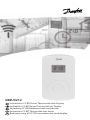
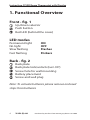
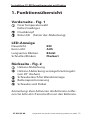
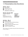
1. Functional Overview
Front - g. 1
Up/down selector
Push button
Red LED (behind the cover)
LED modes
Permanent light ON
No light OFF
Slow ashing Flashes
Fast ashing Flickers
Back - g. 2
Back plate
Back plate lock/unlock (turn 90°)
Screw hole for wall mounting
Battery placement
Screw and wall plug
Note: To activate batteries please remove enclosed
strips from batteries

5VI.UH.Q3.80
Produced by Danfoss Floor Heating Hydronics 01.2006
Instruction CF-RD Room Thermostat with Display
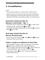
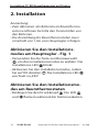
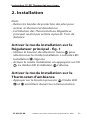
2. Installation
Note:
• To activate batteries in the Room Thermostat
please remove enclosed strips from the batteries.
• The assignment of the Room Thermostats to the
Master Controller should be within 1½m distance
Activate Install mode on
Master Controller - g. 1.
• Use the menu selection button to select the
Install mode. Install LED ashes
• Activate Install mode by pressing OK . Install
LED goes ON
Activate Install mode on
Room Thermostat
• Press the push button . LED and icker
during communication
Select output on Master Controller
• All available output LEDs on Master Controller
light up, and the rst of them ashes
• Press output selection button , select desired
output ( ashes) and accept with OK
• All output LEDs go OFF. Selected output
stays ON shortly

6
VI.UH.Q3.80
Produced by Danfoss Floor Heating Hydronics 01.2006
Instruction CF-RD Room Thermostat with Display
Room Thermostat installation status
• Satisfactory - LED goes OFF
• Not satisfactory - LED ashes 5 times
Note: A Room Thermostat can be assigned to sev-
eral outputs if needed
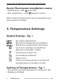
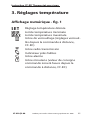
3. Temperature Settings
Digital Display - g. 1
Set value adjustment
Minimum temperature limitation
Maximum temperature limitation
Lock icon (settings locked from
Remote Controller, CF-RC)
Transmission link icon
Low battery indicator
Alarm icon
Timer icon (time & zone control set
from Remote Controller, CF-RC)
Setting of Temperatures - g. 1
• The actual room temperature is shown in the
display as default

7VI.UH.Q3.80
Produced by Danfoss Floor Heating Hydronics 01.2006
Instruction CF-RD Room Thermostat with Display
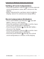
Setting of room temperature
• Press the up/down selector to set the desired
room temperature value, SET is shown in the
display
• When releasing the up/down selector the
display returns to actual room temperature
Room temperature limitation
• Press and hold the push button until SET
MAX is shown in the display
• Press the up/down selector to set the maxi-
mum room temperature limitation
• Press the push button shortly, SET MIN is
shown in the display
• Press the up/down selector to set the mini-
mum room temperature limitation
• Press the push button shortly, the actual
room temperature is shown in the display

8
VI.UH.Q3.80
Produced by Danfoss Floor Heating Hydronics 01.2006
Instruction CF-RD Room Thermostat with Display
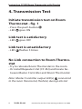
4. Transmission Test
Initiate transmission test on Room
Thermostat - g. 1
• Press the push button
• LED goes ON
Link test is satisfactory
• LED goes OFF
Link test is unsatisfactory
• LED ashes 5 times
No Link connection to Room Thermo-
stat
• Try to relocate Room Thermostat in the room
• Or install Repeater Unit (CF-RU) and locate be-
tween Master Controller and Room Thermostat
Note: Master Controller output LED(s) connected
to the room thermostat, ash(es) during Link test

9VI.UH.Q3.80
Produced by Danfoss Floor Heating Hydronics 01.2006
Instruction CF-RD Room Thermostat with Display
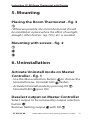
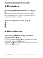
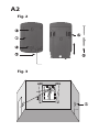
5. Mounting
Placing the Room Thermostat - g. 3
! Wherever possible, the room thermostat should
be installed at a place where the e ect of sunlight,
draught, other heaters (eg. TV’s), etc. is avoided.
Mounting with screws - g. 2
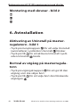
6. Uninstallation
Activate Uninstall mode on Master
Controller - g. 1
• Use the Menu selection button to choose the
Uninstall menu. Uninstall LED ashes
• Activate Uninstall mode by pressing OK .
Uninstall LED goes ON
Deselect output on Master Controller
Select output to be removed by output selection
button
Remove ashing output with OK

10
VI.UH.Q3.80
Produced by Danfoss Floor Heating Hydronics 01.2006
Instruction CF-RD Room Thermostat with Display
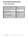
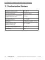
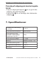
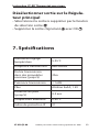
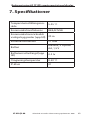
7. Speci cations
Temperature setting range 5-35°C
Transmission frequency 868.42MHz
Transmission range in normal
buildings (up to)
30m
Transmission power < 1mW
Battery Alkaline 2xAA, 1.5V
Battery lifetime (up to) 2-3 years
Ambient temperature 0-50°C
IP class 21

11VI.UH.Q3.80
Produced by Danfoss Floor Heating Hydronics 01.2006
Instruction CF-RD Room Thermostat with Display
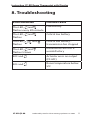
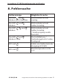
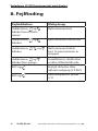
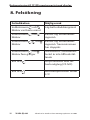
Error Indication Possible Cause
The LED,
and
ashes every 5th minute
Low battery
The LED,
and
ashes
Critical low battery
The LED, , and
ashes
Critical low battery -
transmission has stopped
The LED,
and
ashes 5 times
Installation/Link Test is
unsatisfactory
E03 and
Actuator error on output
(CF-MC)
E05 and
Room temperature below
5ºC
8. Troubleshooting

12
VI.UH.Q3.80
Hergestellt von Danfoss Floor Heating Hydronics 01.2006
Instruktion CF-RD Raumthermostat mit Display
1. Funktionsübersicht . . . . . . . . . . . . . . . . . . . . 13
2. Installation . . . . . . . . . . . . . . . . . . . . . . . . . . . . 14
3. Temperatureinstellungen . . . . . . . . . . . . . . 16
4. Funk - Verbindungstest . . . . . . . . . . . . . . . . 17
5. Montage . . . . . . . . . . . . . . . . . . . . . . . . . . . . . . 18
6. Deinstallation . . . . . . . . . . . . . . . . . . . . . . . . . 19
7. Technische Daten . . . . . . . . . . . . . . . . . . . . . 20
8. Fehlersuche . . . . . . . . . . . . . . . . . . . . . . . . . . . 21
9. Bilder und Zeichnungen . . . . . . . . . . . . A1-A2
Inhaltsverzeichnis

13VI.UH.Q3.80
Hergestellt von Danfoss Floor Heating Hydronics 01.2006
Instruktion CF-RD Raumthermostat mit Display
1. Funktionsübersicht
Vorderseite - Fig. 1
Freie Temperaturwahl
höher/niedriger
Druckknopf
Rote LED (hinter der Abdeckung)
LED-Anzeige
Dauerlicht EIN
Kein Licht AUS
Langsames Blinken Blinkt
Schnelles Blinken Flackert
Rückseite - Fig. 2
Hintere Abdeckung
Hintere Abdeckung verriegeln/entriegeln
(um 90° drehen)
Schraubenloch für Wandmontage
Batteriepositionierung
Schraube und Dübel
Anmerkung: Zum Aktivieren der Batterien entfer-
nen Sie bitte den Trennstreifen von den Batterien.

14
VI.UH.Q3.80
Hergestellt von Danfoss Floor Heating Hydronics 01.2006
Instruktion CF-RD Raumthermostat mit Display
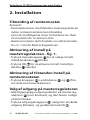
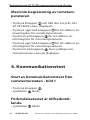
2. Installation
Anmerkung:
• Zum Aktivieren der Batterien im Raumthermo-
staten entfernen Sie bitte den Trennstreifen von
den Batterien.
• Die Anmeldung des Raumthermostaten muss
innerhalb von 1,5m vom Hauptregler erfolgen.
Aktivieren Sie den Installations-
modus am Hauptregler - Fig. 1
• Verwenden Sie die Taste zur Menüauswahl
, um den Installationsmodus zu wählen. Die
Installations-LED blinkt.
• Aktivieren Sie den Installationsmodus, indem
Sie auf OK drücken . Die Installations-LED
wechselt zu „EIN“.
Aktivieren Sie den Installationsmo-
dus am Raumthermostaten
• Betätigen Sie den Druckknopf . Die LED
und ackern während der Kommunikation.

15VI.UH.Q3.80
Hergestellt von Danfoss Floor Heating Hydronics 01.2006
Instruktion CF-RD Raumthermostat mit Display
Wählen Sie den Ausgang am
Hauptregler
• Alle verfügbaren Ausgangs-LED am Hauptregler
leuchten, und die erste LED blinkt.
• Betätigen Sie die Taste zur Ausgangswahl ,
wählen Sie den gewünschten Ausgang (blinkt),
und bestätigen Sie mit OK .
• Alle Ausgangs-LED wechseln zu „AUS“. Der
gewählte Ausgang wechselt kurz zu „EIN“.
Installationsstatus des Raumthermo-
staten
• Wenn OK - LED wechselt zu „AUS“.
• Wenn nicht OK - LED blinkt 5 Mal.
Anmerkung: Ein Raumthermostat kann bei Bedarf
mehreren Ausgängen (Stellantrieben) zugeord-
net werden.

16
VI.UH.Q3.80
Hergestellt von Danfoss Floor Heating Hydronics 01.2006
Instruktion CF-RD Raumthermostat mit Display
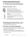
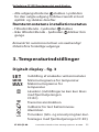
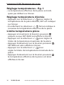
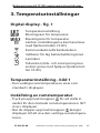
3. Temperatureinstellungen
Digitale Anzeige - Fig. 1
Temperatureinstellung
Mindesttemperaturbegrenzung
Höchsttemperaturbegrenzung
Symbol Sperre (Einstellungen werden
über die Fernbedienung gesperrt,
CF-RC)
Symbol Funk - Sendeverbindung
Anzeige Batterieladezustand niedrig
Symbol Alarm
Symbol Zeit- und Zonenkontrolle, über
die Fernbedienung CF-RC eingestellt
Einstellung der Temperaturen - Fig. 1
• Standardmäßig erscheint in der Anzeige die
tatsächliche Raumtemperatur.
Einstellen der Raumtemperatur
• Drücken Sie den Temperaturwähler , um die
gewünschte Raumtemperatur einzustellen, SET
erscheint in der Anzeige.
• Wenn Sie den Temperaturwähler loslassen,
erscheint in der Anzeige wieder die tatsächliche
Raumtemperatur.

17VI.UH.Q3.80
Hergestellt von Danfoss Floor Heating Hydronics 01.2006
Instruktion CF-RD Raumthermostat mit Display
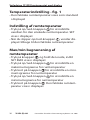
Raumtemperaturbegrenzung
• Halten Sie den Druckknopf gedrückt, bis SET
MAX in der Anzeige erscheint.
• Betätigen Sie den Temperaturwähler , um die
maximale Raumtemperatur einzustellen.
• Betätigen Sie kurz den Druckknopf , SET MIN
erscheint in der Anzeige.
• Betätigen Sie den Temperaturwähler
, um die
niedrigste Raumtemperatur einzustellen.
• Betätigen Sie kurz den Druckknopf , in der
Anzeige erscheint die tatsächliche Raumtem-
peratur.
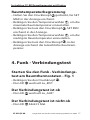
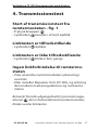
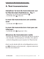
4. Funk - Verbindungstest
Starten Sie den Funk - Verbindungs-
test am Raumthermostaten - Fig. 1
• Betätigen Sie den Druckknopf .
• Die LED wechselt zu „EIN“.
Der Verbindungstest ist ok
• Die LED wechselt zu „AUS“.
Der Verbindungstest ist nicht ok
• Die LED blinkt 5 Mal.

18
VI.UH.Q3.80
Hergestellt von Danfoss Floor Heating Hydronics 01.2006
Instruktion CF-RD Raumthermostat mit Display
Keine Verbindung zum Raumthermo-
staten
Abhilfe:
• Verändern Sie die Position des Raumthermo-
staten im Raum.
• Installieren Sie den Signalverstärker (CF-RU) und
platzieren Sie diesen zwischen dem Hauptregler
und dem Raumthermostaten. Installieren Sie
die externe Antenne (CF-EA).
Anmerkung: Die Ausgangs-LED am Hauptregler
, die mit dem Raumthermostaten zugeordnet
sind, blinken während des Funk - Verbindungstests.
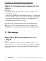
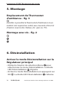
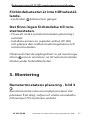
5. Montage
Platzieren des Raumthermostaten
- Fig. 3
Sofern möglich, sollte der Raumthermostat an ei-
nem Ort ohne Sonneneinstrahlung, Luftzug, andere
Wärmequellen (z. B. Fernsehgeräte) usw. installiert
werden.

19VI.UH.Q3.80
Hergestellt von Danfoss Floor Heating Hydronics 01.2006
Instruktion CF-RD Raumthermostat mit Display
Montage mit Schrauben - Fig. 2
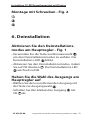
6. Deinstallation
Aktivieren Sie den Deinstallations-
modus am Hauptregler - Fig. 1
• Verwenden Sie die Taste zur Menüauswahl ,
um den Deinstallationsmodus zu wählen. Die
Deinstallations-LED blinkt.
• Aktivieren Sie den Deinstallationsmodus, indem
Sie auf OK drücken . Die Deinstallations-LED
wechselt zu EIN.
Heben Sie die Wahl des Ausgangs am
Hauptregler auf
• Wählen Sie den zu entfernenden Ausgang mit
der Taste zur Ausgangswahl .
• Schalten Sie den blinkenden Ausgang mit
OK ab.
Seite wird geladen ...
Seite wird geladen ...
Seite wird geladen ...
Seite wird geladen ...
Seite wird geladen ...
Seite wird geladen ...
Seite wird geladen ...
Seite wird geladen ...
Seite wird geladen ...
Seite wird geladen ...
Seite wird geladen ...
Seite wird geladen ...
Seite wird geladen ...
Seite wird geladen ...
Seite wird geladen ...
Seite wird geladen ...
Seite wird geladen ...
Seite wird geladen ...
Seite wird geladen ...
Seite wird geladen ...
Seite wird geladen ...
Seite wird geladen ...
Seite wird geladen ...
Seite wird geladen ...
Seite wird geladen ...
Seite wird geladen ...
Seite wird geladen ...
Seite wird geladen ...
Seite wird geladen ...
Seite wird geladen ...
Seite wird geladen ...
Seite wird geladen ...
Seite wird geladen ...
Seite wird geladen ...
-
 1
1
-
 2
2
-
 3
3
-
 4
4
-
 5
5
-
 6
6
-
 7
7
-
 8
8
-
 9
9
-
 10
10
-
 11
11
-
 12
12
-
 13
13
-
 14
14
-
 15
15
-
 16
16
-
 17
17
-
 18
18
-
 19
19
-
 20
20
-
 21
21
-
 22
22
-
 23
23
-
 24
24
-
 25
25
-
 26
26
-
 27
27
-
 28
28
-
 29
29
-
 30
30
-
 31
31
-
 32
32
-
 33
33
-
 34
34
-
 35
35
-
 36
36
-
 37
37
-
 38
38
-
 39
39
-
 40
40
-
 41
41
-
 42
42
-
 43
43
-
 44
44
-
 45
45
-
 46
46
-
 47
47
-
 48
48
-
 49
49
-
 50
50
-
 51
51
-
 52
52
-
 53
53
-
 54
54


Danfoss CF-RD Room Thermostat Installationsanleitung
- Kategorie
- Thermostate
- Typ
- Installationsanleitung
in anderen Sprachen
Verwandte Artikel
-
Danfoss CF-RS Standard Room Thermostat Installationsanleitung
-
-
-
-
-
Danfoss CF-RF Room Thermostat Installationsanleitung
-
-
-
-