Danfoss CF-RF Room Thermostat Installationsanleitung

Typ
Installationsanleitung
SE
088U0213
Instruction CF-RF Room Thermostat with Infrared Floor Sensor
Instruktion CF-RF Raumthermostat mit Infrarot-Bodensensor
Vejledning til CF-RF-rumtermostat med infrarød gulvsensor
Instructions Thermostat d’ambiance CF-RF avec Capteur au sol infrarouge
Instruction CF-RF rumstermostate med infraröd golvsensor
1VI.UH.R1.80
Produced by Danfoss Floor Heating Hydronics 01.2006
Instruction CF-RF Room Thermostat with InfraRed Floor Sensor
GB
Instruction . . . . . . . . . . . . . . . . . . . . . . . 3
D
Instruktion . . . . . . . . . . . . . . . . . . . . . . 15
DK
Vejledning . . . . . . . . . . . . . . . . . . . . . . 28
F
Instruction . . . . . . . . . . . . . . . . . . . . . . 41
SE
Bruksanvisning . . . . . . . . . . . . . . . . . 54
2
VI.UH.R1.80
Produced by Danfoss Floor Heating Hydronics 01.2006
Instruction CF-RF Room Thermostat with InfraRed Floor Sensor
3VI.UH.R1.80
Produced by Danfoss Floor Heating Hydronics 01.2006
Instruction CF-RF Room Thermostat with InfraRed Floor Sensor
1. Functional Overview . . . . . . . . . . . . . . . . . . . . . . . . 4
2. Installation . . . . . . . . . . . . . . . . . . . . . . . . . . . . . . . . . 5
3. Temperature Settings . . . . . . . . . . . . . . . . . . . . . . . 6
4. Transmission Test . . . . . . . . . . . . . . . . . . . . . . . . . . 10
5. Mounting . . . . . . . . . . . . . . . . . . . . . . . . . . . . . . . . . 11
6. Uninstallation . . . . . . . . . . . . . . . . . . . . . . . . . . . . . 12
7. Specications . . . . . . . . . . . . . . . . . . . . . . . . . . . . . . 13
8. Troubleshooting . . . . . . . . . . . . . . . . . . . . . . . . . . . 14
9. Figures and Illustrations . . . . . . . . . . . . . . . . A1-A2
GB
Index
4
VI.UH.R1.80
Produced by Danfoss Floor Heating Hydronics 01.2006
Instruction CF-RF Room Thermostat with InfraRed Floor Sensor
1. Functional Overview
Front - g. 1
Up/down selector
Push button
Red LED (behind the cover)
InfraRed oor sensor
LED modes
Permanent light ON
No light OFF
Slow ashing Flashes
Fast ashing Flickers
Back - g. 2
Back plate
Back plate lock/unlock (turn 90°)
Screw hole for wall mounting
Battery placement
Screw and wall plug
5VI.UH.R1.80
Produced by Danfoss Floor Heating Hydronics 01.2006
Instruction CF-RF Room Thermostat with InfraRed Floor Sensor
2. Installation
Note:
To activate batteries in the Room Thermostat,
please remove enclosed strips from the batteries.
The assignment of the Room Thermostats to the
Master Controller should be within 1½ m distance
Activate Install mode on
Master Controller - g. 1.
Use the menu selection button to select the
Install mode. Install LED ashes
Activate Install mode by pressing OK . Install
LED goes ON
Activate Install mode on
Room Thermostat
Press the push button . LED and icker
during communication
Select output on Master Controller
All available output LEDs on Master Controller
light up, and the rst of them ashes
Press output selection button , to select
desired output (ashes) and accept with OK
All output LEDs go OFF. Selected output
stays ON shortly
6
VI.UH.R1.80
Produced by Danfoss Floor Heating Hydronics 01.2006
Instruction CF-RF Room Thermostat with InfraRed Floor Sensor
Room Thermostat installation status
Satisfactory - LED goes OFF
Not satisfactory - LED ashes 5 times
Note: A Room Thermostat can be assigned to sev-
eral outputs if needed by repeating the installation
process.
3. Temperature Settings
Digital Display - g. 1
Set value adjustment
Minimum temperature limitation
Maximum temperature limitation
Lock icon (settings locked from
Remote Controller, CF-RC)
Transmission link icon
Low battery indicator
Alarm icon
Timer icon (time program is active from
Remote Controller, CF-RC)
Room temperature
Floor surface temperature
7VI.UH.R1.80
Produced by Danfoss Floor Heating Hydronics 01.2006
Instruction CF-RF Room Thermostat with InfraRed Floor Sensor
Changing default display temperature
- g. 1.
1. The actual room temperature is shown in the
display as default
2. To change default display from actual room
temperature to actual oor surface tempera-
ture, press and hold the push button
until SET MAX is shown in the display
3. Press the button shortly and repeatedly
until
or is ashing in the display
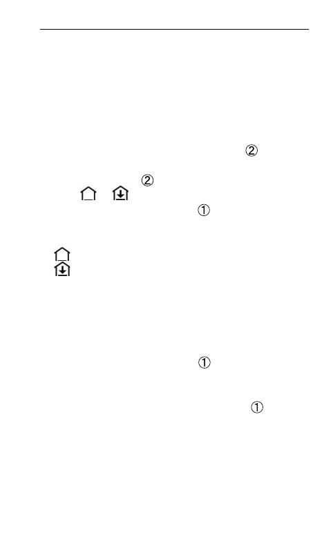
4. Press the up/down selector to select the
new default display temperature:
Room temperature
Floor surface temperature
Setting of room temperature
1. Make sure actual room temperature is shown
in the display
2. Press the up/down selector to set the
desired room temperature value. SET is shown
in the display
3. When releasing the up/down selector the
display returns to actual temperature
Note: The thermostat regulates the oor heating
system according to room temperature set point,
within the maximum and minimum limitations
dened for the oor surface temperature
8
VI.UH.R1.80
Produced by Danfoss Floor Heating Hydronics 01.2006
Instruction CF-RF Room Thermostat with InfraRed Floor Sensor
Room temperature limitation
1. Make sure actual room temperature is shown
in the display
2. Press the push button until SET MAX is
shown in the display
3. Press the up/down selector to set the
maximum room temperature limitation
4. Press the push button shortly, SET MIN is
shown in the display
5. Press the up/down selector to set the mini-
mum room temperature limitation
6. Press the push button shortly and the
actual oor surface temperature is shown in
the display
Floor surface temperature limitation
1. Ensure actual oor surface temperature is
shown in the display illustrated by
2. Press and hold the push button until SET
MAX is also shown in the display
3. Press the up/down selector to set the
maximum oor surface temperature limitation
4. Press the push button shortly, SET MIN is
also shown in the display
5. Press the up/down selector to set the mini-
mum oor surface temperature limitation
9VI.UH.R1.80
Produced by Danfoss Floor Heating Hydronics 01.2006
Instruction CF-RF Room Thermostat with InfraRed Floor Sensor
IMPORTANT!
As heat emission from the oor may vary slightly
depending on oor covering - and thereby cause
inaccurate temperature measurement - it may be
necessary to adjust the setting of max. and min.
oor surface temperatures accordingly.
! It is important always to follow recommendations
from the oor manufacturer regarding max. oor
surface temperature.
! It is recommended always to include mixing shunt
for oor heating circuits in order to ensure optimal
ow temperature. - In addition to minimised energy
consumption, correct setting of the ow tempera-
ture will eliminate the risk of excessive heat transfer
to the oor.
10
VI.UH.R1.80
Produced by Danfoss Floor Heating Hydronics 01.2006
Instruction CF-RF Room Thermostat with InfraRed Floor Sensor
4. Transmission Test
Initiate transmission test on Room
Thermostat - g. 1
Press the push button
LED goes ON
Link test is satisfactory
LED goes OFF
Link test is unsatisfactory
LED ashes 5 times
No link connection to Room Thermostat
Try to relocate Room Thermostat in the room
Or install Repeater Unit (CF-RU) and locate
between Master Controller and Room
Thermostat
Note: Master Controller output LED(s) connected
to the Room thermostat, ash(es) during link test
11VI.UH.R1.80
Produced by Danfoss Floor Heating Hydronics 01.2006
Instruction CF-RF Room Thermostat with InfraRed Floor Sensor
5. Mounting
Placing the Room Thermostat - g. 3
The Room Thermostat should be placed in
accordance with g. 3
IMPORTANT!
Wherever possible, the room thermostat should
be installed at a place where the eect of sunlight,
strong articial light (e.g. halogen spotlight),
draught, other heat-emitting equipment (e.g. TVs)
etc. is avoided.
! Please note that no furniture, rugs etc. should be
permanently placed within the area of the InfraRed
Floor Sensor as shown in g. 3.
Mounting - g. 2
1. Mount the back plate with the two screws
and wall plugs via the screw holes in the
back plate
2. Slide thermostat into place on the back plate
3. If desired lock the thermostat to the back plate
with Allen key (turn 90°)
12
VI.UH.R1.80
Produced by Danfoss Floor Heating Hydronics 01.2006
Instruction CF-RF Room Thermostat with InfraRed Floor Sensor
6. Uninstallation
Activate Uninstall mode on Master
Controller - g. 1
Use the Menu selection button to choose
the Uninstall menu. Uninstall LED ashes
Activate Uninstall mode by pressing OK .
Uninstall LED goes ON
Deselect output on Master Controller
Select output to be removed by output selec-
tion button
Remove ashing output with OK
13VI.UH.R1.80
Produced by Danfoss Floor Heating Hydronics 01.2006
Instruction CF-RF Room Thermostat with InfraRed Floor Sensor
Temperature setting
range
5-35°C
Transmission frequency 868.42MHz
Transmission range in
normal buildings (up to)
30m
Transmission power < 1mW
Battery Alkaline 2xAA, 1.5V
Battery lifetime
(up to)
1-3 years
Ambient temperature 0-50°C
IP class 21
Sensor accuracy +/- 1°C
Sensor emission coef-
cient
0.9
7. Specications
14
VI.UH.R1.80
Produced by Danfoss Floor Heating Hydronics 01.2006
Instruction CF-RF Room Thermostat with InfraRed Floor Sensor
Error Indication Possible Cause
The LED, and
ashes every 5th minute
Low battery
The LED, and
ashes
Critical low battery
The LED, , and
ashes
Critical low battery -
transmission has stopped
The LED, and
ashes 5 times
Installation/link Test is
unsatisfactory
E03 and
Actuator error on output
(CF-MC)
E05 and
Room temperature below
5ºC
8. Troubleshooting
15VI.UH.R1.80
Hergestellt von Danfoss Floor Heating Hydronics 01.2006
Instruktion CF-RF Raumthermostat mit Infrarot-Oberächenfühler
1. Funktionsübersicht ................................................ 16
2. Installation ................................................................. 17
3. Temperatureinstellungen ....................................18
4. Funk - Verbindungstest .........................................23
5. Montage ...................................................................... 24
6. Deinstallation ........................................................... 25
7. Technische Daten .....................................................26
8. Fehlersuche ................................................................27
9. Bilder und Zeichnungen .............................. A1-A2
D
Inhaltsverzeichnis
Instruktion CF-RF Raumthermostat mit Infrarot-Oberächenfühler
16
VI.UH.R1.80
Hergestellt von Danfoss Floor Heating Hydronics 01.2006
1. Funktionsübersicht
Vorderseite - Fig. 1
Freie Temperaturwahl
Druckknopf
Rote LED (hinter der Abdeckung)
Infrarot-Oberächenfühler
LED Anzeige
Dauerlicht EIN
Leuchtet nicht AUS
Blinkt langsam Blinkt
Blinkt schnell Flackert
Rückseite - Fig. 2
Hintere Abdeckung
Hintere Abdeckung verriegeln / entriegeln
(um 90° drehen)
Schraubenloch für Wandmontage
Batteriepositionierung
Schraube und Dübel
17VI.UH.R1.80
Hergestellt von Danfoss Floor Heating Hydronics 01.2006
Instruktion CF-RF Raumthermostat mit Infrarot-Oberächenfühler
2. Installation
Anmerkung:
Zum Aktivieren der Batterien im Raumthermosta-
ten entfernen Sie bitte den Trennstreifen von den
Batterien.
Die Anmeldung des Raumthermostaten muss
innerhalb von 1,5 m vom Hauptregler erfolgen.
Aktivieren Sie den Installationsmo-
dus am Hauptregler – Fig. 1
Verwenden Sie die Taste zur Menüauswahl ,
um den Installationsmodus zu wählen.
Die Installations-LED blinkt.
• Aktivieren Sie den Installationsmodus, indem
Sie auf OK drücken . Die Installations-LED
wechselt zu „EIN“.
Aktivieren Sie den Installations-
modus am Raumthermostaten
• Betätigen Sie den Druckknopf . Die LED
und ackern während der Kommunikation.
Wählen Sie den Ausgang am Haupt-
regler
• Alle verfügbaren Ausgangs-LED am Hauptregler
leuchten, und die erste LED blinkt.
Instruktion CF-RF Raumthermostat mit Infrarot-Oberächenfühler
18
VI.UH.R1.80
Hergestellt von Danfoss Floor Heating Hydronics 01.2006
• Betätigen Sie die Taste zur Ausgangswahl
wählen Sie den gewünschten Ausgang (blinkt),
und bestätigen Sie mit OK .
Alle Ausgangs-LED wechseln zu „AUS“.
Der gewählte Ausgang wechselt kurz zu „EIN“.
Installationsstatus des Raumthermo-
staten
Wenn OK - LED wechselt zu „AUS“.
Wenn nicht OK - LED blinkt 5 Mal.
Anmerkung: Ein Raumthermostat kann bei Bedarf
mehreren Ausgängen (Stellantrieben) zugeord-
net werden.
3. Temperatureinstellungen
Digitalanzeige - Fig. 1.
Temperatureinstellung
Min. Temperaturbegrenzung
Max. Temperaturbegrenzung
Symbol Sperre (Einstellungen werden
über die Fernbedienung CF-RC gesperrt)
19VI.UH.R1.80
Hergestellt von Danfoss Floor Heating Hydronics 01.2006
Instruktion CF-RF Raumthermostat mit Infrarot-Oberächenfühler
Symbol Funk-Sendeverbindung
Anzeige Batterieladezustand niedrig
Symbol Alarm
Symbol (Zeit- und Zonenkontrolle,
über die Fernbedienung CF- RC
eingestellt)
Raumtemperatur
Bodenoberächentemperatur
Änderung der voreingestellten Tem-
peratur auf dem Display - Fig. 1.
1. In der Grundeinstellung wird auf dem Display
die tatsächliche Raumtemperatur angezeigt.
2. Um diese Grundeinstellung von der Raum-
temperatur auf die Bodenoberächentempe-
ratur zu ändern, drücken Sie Druckknopf
so lange, bis EINST MAX auf dem Display
erscheint.
3. Kurz und wiederholt auf den Druckknopf
drücken, bis oder auf dem Display
blinkt.
4. Den hoch/niedrig Druckknopf betätigen,
um die neue voreingestellte Bildschirm-
temperatur zu wählen:
Raumtemperatur
Bodenoberächentemperatur
1 / 1

Danfoss CF-RF Room Thermostat Installationsanleitung

Typ
Installationsanleitung