Yamaha RX-V659 Bedienungsanleitung
- Kategorie
- AV-Receiver
- Typ
- Bedienungsanleitung

YAMAHA ELECTRONICS CORPORATION, USA
6660 ORANGETHORPE AVE., BUENA PARK, CALIF. 90620, U.S.A.
YAMAHA CANADA MUSIC LTD.
135 MILNER AVE., SCARBOROUGH, ONTARIO M1S 3R1, CANADA
YAMAHA ELECTRONIK EUROPA G.m.b.H.
SIEMENSSTR. 22-34, 25462 RELLINGEN BEI HAMBURG, GERMANY
YAMAHA ELECTRONIQUE FRANCE S.A.
RUE AMBROISE CROIZAT BP70 CROISSY-BEAUBOURG 77312 MARNE-LA-VALLEE CEDEX02, FRANCE
YAMAHA ELECTRONICS (UK) LTD.
YAMAHA HOUSE, 200 RICKMANSWORTH ROAD WATFORD, HERTS WD18 7GQ, ENGLAND
YAMAHA SCANDINAVIA A.B.
J A WETTERGRENS GATA 1, BOX 30053, 400 43 VÄSTRA FRÖLUNDA, SWEDEN
YAMAHA MUSIC AUSTRALIA PTY, LTD.
17-33 MARKET ST., SOUTH MELBOURNE, 3205 VIC., AUSTRALIA
©
2006 All rights reserved.
RX-V659
Printed in Malaysia WG73810
RX-V659
AV Receiver
Ampli-tuner audio-vidéo
OWNER’S MANUAL
MODE D’EMPLOI
BEDIENUNGSANLEITUNG
BRUKSANVISNING
GEBRUIKSAANWIJZING
ИНСТРУКЦИЯ ПО ЭКСПЛУАТАЦИИ
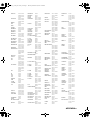
G
QUAD 60157
QUASAR 60029
RADIOLA 60157
RADIOTONE 60625
RCA 60032, 60179
REALISTIC 60179
RESTEK 60157
REVOX 60157
ROTEL 60157, 60897
SAE 60157
SAMSUNG 60524
SANSUI 60157, 60625
SANYO 60179
SEG 60625
SHARP 60034
SHERWOOD 60426
SIEMENS 60157, 60362
SIMAUDIO 60157
SONIC FRONTIERS
60157
SONY 60000
STS 60018
SUPERTECH 60625
SYNERGY 60625
TAG MCLAREN
60157
TANDY 60032
TEAC 60362, 60393,
60625, 60643
TECHNICS 60029, 60207,
60303
TECHWOOD 60362
THORENS 60157
THULE AUDIO60157
TOSHIBA 60299, 60481
TRAXDATA 60626
UNIVERSUM 60157, 60362,
60524
WARDS 60000, 60032,
60157, 60179
YAMAHA 60036, 61907
YBA 60625
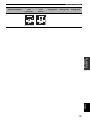
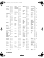
CD RECORDER
DENON 70626, 70766
HHB 70192
JVC 71294
KENWOOD 70626
LG 71208
MARANTZ 70626
NAD 71208
PHILIPS 70626
PIONEER 70192, 71087
RCA 70420
SONY 70000
TDK 71208
TEAC 70420
VICTOR 70072, 71294
YAMAHA 70888, 71292
MD RECORDER
DENON 70873
KENWOOD 70681
OPTIMUS 71063
PIONEER 71063
SHARP 70861, 71684
SONY 70490
TECHNICS 71078
YAMAHA 70490, 70888,
71909
TAPE DECK
AIWA 70029, 70197
AKAI 70189, 70283
ARCAM 70076
CARVER 70029
DENON 70076
EROICA 70189
GARRARD 70308, 70309
GRUNDIG 70029
HARMAN/KARDON
70029
INKEL 70070
JVC 70244, 70273
KENWOOD 70070, 70205
MAGNAVOX 70029
MARANTZ 70029
MITSUBISHI 70189, 70283
MYRYAD 70029
ONKYO 70135, 70282
OPTIMUS 70027, 70220
ORION 70308, 70309
PANASONIC 70229
PHILIPS 70029, 70229
PIONEER 70027, 70220
POLK AUDIO 70029
RADIOLA 70029
RCA 70027, 70220
REVOX 70029
SANSUI 70029
SHARP 70205, 70231
SONY 70170, 70243
TEAC 70283, 70289,
70308, 70309
TECHNICS 70229
THORENS 70029
VICTOR 70244, 70273
WARDS 70027, 70029
YAMAHA 70097, 70205,
70524
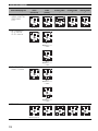
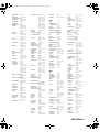
TUNER
ACOUSTIC SOLUTIONS
81467
AIWA 80158, 80189
AKAI 80115, 80609
ANAM 80281, 80609
ARCAM 80189
CAIRN 80189
CAMBRIDGE 80189
CAMBRIDGE AUDIO
81455, 81647
CARVER 80189
DENON 80004, 80273
DUAL 80004
GARRARD 80281
GOLDMUND 80189
GOLDSTAR 80281
GOODMANS 80609
GRADIENTE 80281
GRUNDIG 80189, 80281
HARMAN/KARDON
80110, 80189
INKEL 80027, 80066
JBL 80110
JVC 80074
KENWOOD 80027, 80645
LG 80281
LINN 80189
LOEWE 80189
MAGNAVOX 80189
MARANTZ 80189
MEMOREX 80014
MICROMEGA 80189
MUSICAL FIDELITY
80445
MYRYAD 80189
NAD 80320, 80609
NIKKO 80609
ONKYO 80103, 80119
PANASONIC 80309, 80518
PHILIPS 80189
PIONEER 80014
POLK AUDIO 80189
RADIOLA 80189
RESTEK 80189
REVOX 80140, 80189
SANSUI 80189, 80609
SHERWOOD 80066
SIEMENS 80609
SONIC 80281
SONY 80158
SOUNDWAVE 80609
TEAC 80110, 80609
TECHNICS 80309, 80518,
81135
TECHWOOD 80281, 80609
THORENS 80189
UNIVERSUM 80189, 80281,
80609
VICTOR 80074
WARDS 80014, 80158,
80189
YAMAHA 80293, 81908
(TUNER ID1) 81916
(TUNER ID2) 81917
ZENITH 80281
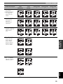
OTHER AUDIO
ACCESSORIES
YAMAHA (iPod) 81981
RX-V659_G_cv.fm Page 1 Wednesday, December 7, 2005 11:09 AM

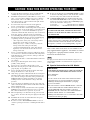
CAUTION: READ THIS BEFORE OPERATING YOUR UNIT.
1 To assure the finest performance, please read this manual
carefully. Keep it in a safe place for future reference.
2 Install this sound system in a well ventilated, cool, dry, clean
place – away from direct sunlight, heat sources, vibration,
dust, moisture, and/or cold. Allow ventilation space of at
least 30 cm on the top, 20 cm on the left and right, and 20
cm on the back of this unit.
3 Locate this unit away from other electrical appliances,
motors, or transformers to avoid humming sounds.
4 Do not expose this unit to sudden temperature changes from
cold to hot, and do not locate this unit in a environment with
high humidity (i.e. a room with a humidifier) to prevent
condensation inside this unit, which may cause an electrical
shock, fire, damage to this unit, and/or personal injury.
5 Avoid installing this unit where foreign object may fall onto
this unit and/or this unit may be exposed to liquid dripping
or splashing. On the top of this unit, do not place:
– other components, as they may cause damage and/or
discoloration on the surface of this unit.
– burning objects (i.e. candles), as they may cause fire,
damage to this unit, and/or personal injury.
– containers with liquid in them, as they may fall and
liquid may cause electrical shock to the user and/or
damage to this unit.
6 Do not cover this unit with a newspaper, tablecloth, curtain,
etc. in order not to obstruct heat radiation. If the temperature
inside this unit rises, it may cause fire, damage to this unit,
and/or personal injury.
7 Do not plug in this unit to a wall outlet until all connections
are complete.
8 Do not operate this unit upside-down. It may overheat,
possibly causing damage.
9 Do not use force on switches, knobs and/or cords.
10 When disconnecting the power cable from the wall outlet,
grasp the plug; do not pull the cord.
11 Do not clean this unit with chemical solvents; this might
damage the finish. Use a clean, dry cloth.
12 Only voltage specified on this unit must be used. Using this
unit with a higher voltage than specified is dangerous and
may cause fire, damage to this unit, and/or personal injury.
YAMAHA will not be held responsible for any damage
resulting from use of this unit with a voltage other than
specified.
13 To prevent damage by lightning, keep the power cable and
outdoor antennas disconnected from a wall outlet or this unit
during a lightning storm.
14 Do not attempt to modify or fix this unit. Contact qualified
YAMAHA service personnel when any service is needed.
The cabinet should never be opened for any reasons.
15 When not planning to use this unit for long periods of time
(i.e. vacation), disconnect the AC power plug from the wall
outlet.
16 Install this unit near the AC wall outlet where the power
cable plug can be reached easily.
17 Be sure to read the “TROUBLESHOOTING” section on
common operating errors before concluding that this unit is
faulty.
18 Before moving this unit, press MASTER ON/OFF to release
it outward to the OFF position to turn off this unit, and then
disconnect the power cable from the AC wall outlet.
19 VOLTAGE SELECTOR (Asia and General models only)
The VOLTAGE SELECTOR on the rear panel of this unit
must be set for your local main voltage BEFORE plugging
into the AC wall outlet. Voltages are:
Asia model ............................ 220/230–240 V AC, 50/60 Hz
General model ........ 110/120/220/230–240 V AC, 50/60 Hz
■ For U.K. customers
If the socket outlets in the home are not suitable for the
plug supplied with this appliance, it should be cut off and
an appropriate 3 pin plug fitted. For details, refer to the
instructions described below.
The plug severed from the mains lead must be destroyed, as a
plug with bared flexible cord is hazardous if engaged in a live
socket outlet.
■ Special Instructions for U.K. Model
CAUTION: READ THIS BEFORE OPERATING YOUR UNIT.
WARNING
TO REDUCE THE RISK OF FIRE OR ELECTRIC
SHOCK, DO NOT EXPOSE THIS UNIT TO RAIN
OR MOISTURE.
This unit is not disconnected from the AC power
source as long as it is connected to the wall outlet, even
if this unit itself is turned off. In this state, this unit is
designed to consume a very small quantity of power.
Note
IMPORTANT
THE WIRES IN MAINS LEAD ARE COLOURED IN
ACCORDANCE WITH THE FOLLOWING CODE:
Blue: NEUTRAL
Brown: LIVE
As the colours of the wires in the mains lead of this
apparatus may not correspond with the coloured
markings identifying the terminals in your plug,
proceed as follows:
The wire which is coloured BLUE must be connected
to the terminal which is marked with the letter N or
coloured BLACK. The wire which is coloured
BROWN must be connected to the terminal which is
marked with the letter L or coloured RED.
Making sure that neither core is connected to the earth
terminal of the three pin plug.

1
PREPARATIONINTRODUCTION
BASIC
OPERATION
SOUND FIELD
PROGRAMS
ADVANCED
OPERATION
ADDITIONAL
INFORMATION
English
FEATURES............................................................. 2
GETTING STARTED............................................ 3
Supplied accessories .................................................. 3
Installing batteries in the remote control ................... 3
CONTROLS AND FUNCTIONS ......................... 4
Front panel ................................................................. 4
Remote control........................................................... 6
Front panel display .................................................... 9
Rear panel ................................................................ 11
CONNECTIONS .................................................. 12
Placing speakers....................................................... 12
Connecting speakers ................................................ 13
Information on jacks and cable plugs ...................... 17
Audio and video signal flow.................................... 18
Connecting a TV...................................................... 19
Connecting a DVD player, a DVD recorder,
a VCR or an STB................................................. 20
Connecting a CD player, an MD player,
a tape deck or a turntable..................................... 23
Connecting a YAMAHA iPod universal dock ........ 24
Connecting an external amplifier............................. 25
Connecting a multi-format player
or an external decoder ......................................... 26
Connecting a game console, a video camera
or a portable audio player.................................... 27
Connecting the FM and AM antennas ..................... 28
Connecting the power cable..................................... 29
Setting the speaker impedance................................. 30
Turning on and off the power .................................. 31
AUTO SETUP....................................................... 32
Connecting the optimizer microphone..................... 32
Using AUTO SETUP .............................................. 33
PLAYBACK.......................................................... 38
USING AUDIO FEATURES............................... 40
Using SILENT CINEMA ........................................ 40
Muting the audio output........................................... 40
Selecting the night listening mode........................... 40
Selecting the input mode ......................................... 41
Using the sleep timer ............................................... 41
Adjusting the speaker level...................................... 42
Selecting the Compressed Music
Enhancer mode .................................................... 43
Selecting the MULTI CH INPUT component......... 44
Enjoying multi-channel sources
in 2-channel stereo............................................... 45
Enjoying unprocessed input sources........................ 45
Enjoying pure hi-fi stereo sound.............................. 45
USING VIDEO FEATURES ............................... 46
Displaying the input source information ................. 46
Selecting the OSD mode.......................................... 47
Playing video sources in the background ................ 47
ENJOYING SURROUND SOUND.....................48
Enjoying multi-channel sources in surround ........... 48
Enjoying 2-channel sources in surround.................. 49
Using Virtual CINEMA DSP .................................. 50
RECORDING........................................................51
FM/AM TUNING..................................................52
Automatic tuning ..................................................... 52
Manual tuning.......................................................... 53
Automatic preset tuning........................................... 54
Manual preset tuning ............................................... 55
Selecting preset stations........................................... 56
Exchanging preset stations ...................................... 57
RADIO DATA SYSTEM TUNING
(U.K. AND EUROPE MODELS ONLY)........59
Selecting the Radio Data System program .............. 59
Using the Radio Data System station network ........ 60
Displaying the Radio Data System information ...... 61
SOUND FIELD PROGRAMS .............................63
Selecting sound field programs ............................... 63
Sound field program descriptions............................ 64
Changing sound field parameter settings................. 66
Sound field program speaker layouts ...................... 72
SET MENU ............................................................76
Using SET MENU................................................... 78
1 SOUND MENU.................................................... 79
2 INPUT MENU...................................................... 85
3 OPTION MENU................................................... 87
ADVANCED SETUP............................................90
REMOTE CONTROL FEATURES ...................92
Controlling this unit, a TV,
or other components ............................................ 92
Setting the remote control code ............................... 94
Setting library codes ................................................ 95
Resetting all remote control codes........................... 96
USING MULTI-ZONE CONFIGURATION.....97
Connecting Zone 2................................................... 97
Controlling Zone 2................................................... 99
USING iPod
®
.......................................................101
Setting the remote control code ............................. 101
Controlling iPod .................................................... 101
RESETTING THE SYSTEM.............................103
TROUBLESHOOTING .....................................104
GLOSSARY.........................................................111
Audio information ................................................. 111
Video information.................................................. 112
Sound field program information .......................... 113
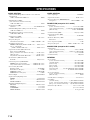
SPECIFICATIONS.............................................114
CONTENTS
INTRODUCTION
PREPARATION
BASIC OPERATION
SOUND FIELD PROGRAMS
ADVANCED OPERATION
ADDITIONAL INFORMATION

FEATURES
2
Built-in 7-channel power amplifier
◆ Minimum RMS output power
(0.06% THD, 20 Hz to 20 kHz, 8 Ω)
Front: 100 W + 100 W
Center: 100 W
Surround: 100 W + 100 W
Surround back: 100 W + 100 W
Sound field programs
◆ Proprietary YAMAHA technology for the creation of sound
fields
◆ Dolby Digital/Dolby Digital EX decoder
◆ DTS/DTS-ES Matrix 6.1, Discrete 6.1, DTS Neo:6, DTS 96/
24 decoder
◆ Dolby Pro Logic/Dolby Pro Logic II/Dolby Pro Logic IIx
decoder
◆ Virtual CINEMA DSP
◆ SILENT CINEMA
™
Sophisticated AM/FM tuner
◆ 40-station random and direct preset tuning
◆ Automatic preset tuning
◆ Preset station shifting capability (preset editing)
Radio Data System
(U.K. and Europe models only)
◆ Radio Data System tuning capability
iPod controlling capability
◆ DOCK terminal to connect a YAMAHA iPod universal dock
(such as YDS-10 sold separately), which supports iPod (Click
and Wheel), iPod nano, and iPod mini
Other features
◆ YPAO (YAMAHA Parametric Room Acoustic Optimizer) for
automatic speaker setup
◆ 192-kHz/24-bit D/A converter
◆ OSD (on-screen display) menus that allow you to optimize
this unit to suit your individual audiovisual system
◆ 8 additional input jacks for discrete multi-channel input
◆ Pure Direct mode for pure hi-fi stereo sound with analog and
PCM sources
◆ S-video signal input/output capability
◆ Component video input/output capability
(3 COMPONENT VIDEO INs and 1 MONITOR OUT)
◆ Digital video signal conversion (composite video ↔ S-video
→ component video) capability for monitor out
◆ Optical and coaxial digital audio signal jacks
◆ Sleep timer
◆ Cinema and music night listening modes
◆ Remote control with preset remote control codes,
backlighting input selector buttons, and an iPod (stationed in a
YAMAHA iPod universal dock connected to the DOCK
terminal) controlling capability
◆ Zone 2 custom installation facility
◆ Zone switching capability between the main zone and Zone 2
using ZONE CONTROL
◆ Compressed Music Enhancer mode to improve the sound
quality of compression artifacts (such as the MP3 format) to
that of a high-quality stereo
• y indicates a tip for your operation.
• Some operations can be performed by using either the buttons on the front panel or the ones on the remote control. In case the button
names differ between the front panel and the remote control, the button name on the remote control is given in parentheses.
• This manual is printed prior to production. Design and specifications are subject to change in part as a result of improvements, etc. In
case of differences between the manual and product, the product has priority.
Manufactured under license from Dolby Laboratories.
“Dolby”, “Pro Logic”, and the double-D symbol are trademarks
of Dolby Laboratories.
Manufactured under license from Digital Theater Systems, Inc.
“DTS”, “DTS-ES”, “NEO:6”, and “DTS 96/24” are trademarks
of Digital Theater Systems, Inc. Copyright 1996, 2003 Digital
Theater Systems, Inc. All right reserved.
“iPod” is a trademark of Apple Computer, Inc., registered in the
U.S. and other countries.
“SILENT CINEMA” is a trademark of YAMAHA
CORPORATION.
FEATURES
Notes
iPod
®

GETTING STARTED
3
INTRODUCTION
English
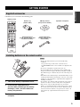
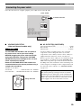
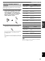
Check that you received all of the following parts.
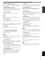
1 Take off the battery compartment cover.
2 Insert the two supplied batteries
(AA, R6, UM-3) according to the polarity
markings (+ and –) on the inside of the
battery compartment.
3 Snap the battery compartment cover back
into place.
• Change all of the batteries if you notice the following
conditions:
– the operation range of the remote control decreases.
– the TRANSMIT indicator does not flash or its light becomes
dim.
• Do not use an old battery together with a new one.
• Do not use different types of batteries (such as alkaline and
manganese batteries) together. Read the packaging carefully as
these different types of batteries may have the same shape and
color.
• If the batteries have leaked, dispose of them immediately. Avoid
touching the leaked material or letting it come into contact with
clothing, etc. Clean the battery compartment thoroughly before
installing new batteries.
• Do not throw away batteries with general house waste; dispose
of them correctly in accordance with your local regulations.
• If the remote control is without batteries for more than 2
minutes, or if exhausted batteries remain in the remote control,
the contents of the memory may be cleared. When the memory
is cleared, insert new batteries, set up the remote control code
and program any acquired functions that may have been
cleared.
GETTING STARTED
Supplied accessories
Installing batteries in the remote control
TV MUTE TV INPUT
MUTE
AMP
SOURCE
TV
MENUTITLE
SET MENU
LEVEL
DISPLAYRETURN
BAND
A/B/C/D/E
ENTER
PRESET/CH
REC
AUDIO
DISC SKIP
STEREO
1
EFFECT
VOLUME
TV VOL TV CH
TRANSMITCODE SET
STANDBY
POWER
POWERPOWER
CD
AVTV
MULTI CH IN
SLEEP
CD-R
DVD DTV
MD
CBL
TUNER
V-AU X DVR
STANDARD
5
SPEAKERS
9
MUSIC
2
SELECT
6
ENHANCER
0
ENTERTAIN
3
EXTD SUR.
7
NIGHT
10
MOVIE
4
PURE DIRECT
8
STRAIGHT
ENT.
FREQ/TEXT EONSTARTPTY SEEKMODE
VCR
PHONO
ON SCREEN
Remote control
Batteries (2)
(AA, R6, UM-3)
Indoor FM antenna
(U.S.A., Canada, China, Asia
and General models)
AM loop antenna
(except for U.K. model)
Indoor FM antenna
(Europe, Australia and
Korea models)
Optimizer microphone
1
3
2
Notes

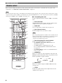
CONTROLS AND FUNCTIONS
4
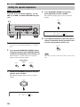
1 MASTER ON/OFF
Turns on or off this unit (see page 31).
2 MAIN ZONE ON/OFF
Turns on the main zone or sets it to the standby mode
(see page 31).
• In the standby mode, this unit consumes a small amount of
power in order to receive infrared signals from the remote
control.
• When you turn on this unit, there will be a 4 to 5-second delay
before this unit can reproduce sound.
• This button is operational only when MASTER ON/OFF is
pressed inward to the ON position.
3 OPTIMIZER MIC jack
Use to connect and input audio signals from the supplied
optimizer microphone in the “AUTO SETUP” procedure
(see page 32).
4 Remote control sensor
Receives signals from the remote control (see page 8).
5 Front panel display
Shows information about the operational status of this unit
(see page 9).
6 A/B/C/D/E, NEXT
• Selects one of the 5 preset station groups (A to E) when
“TUNER” is selected as the input source (see page 52).
• Selects the speaker channel whose output level you
want to adjust when “TUNER” is not selected as the
input source (see page 42).
7 PRESET/TUNING l / h, LEVEL +/–
• Selects one of the 8 preset station numbers (1 to 8)
when “TUNER” is selected as the input source. The
colon (:) is displayed in the front panel display (see
page 52).
• Selects the tuning frequency when “TUNER” is
selected as the input source. The colon (:) is not
displayed in the front panel display (see page 52).
• Adjusts the level of the speaker channel selected using
NEXT when “TUNER” is not selected as the input
source (see page 42).
CONTROLS AND FUNCTIONS
Front panel
ZONE 2
ON/OFF
ZONE
CONTROL
NEXTEDIT
EFFECT
MEMORY
FM/AM
PRESET/TUNING
A/B/C/D/E
PROGRAM
l PRESET/TUNING h
TUNING MODE
INPUT MODETONE CONTROLSTRAIGHT
SPEAKERSPHONES
MAIN ZONE
MASTER
SILENT CINEMA
BA
MULTI CH
INPUT
VOLUME
INPUT
ON OFF
LEVEL
MAN'L/AUTO FM
AUTO/MAN'L
OPTIMIZER MIC
PURE DIRECT
S VIDEO VIDEO OPTICALL AUDIO R
VIDEO AUX
ON/OFF
3145687
IJKGFD
A
L
B
C
2
EH
90
MN
Notes

CONTROLS AND FUNCTIONS
5
INTRODUCTION
English
8 MEMORY (MAN’L/AUTO FM)
Stores a preset station in the memory. Hold down this
button for more than 3 seconds to start automatic preset
tuning (see page 54).
9 TUNING MODE (AUTO/MAN’L)
Switches between automatic tuning (the AUTO indicator
is turned on) and manual tuning (the AUTO indicator is
turned off) (see page 52).
0 ZONE 2 ON/OFF
Turns on Zone 2 or sets it to the standby mode
(see page 99).
This button is operational only when MASTER ON/OFF is
pressed inward to the ON position.
A ZONE CONTROL
Switches the zone you want to control between the main
zone and Zone 2 (see page 99).
y
When Zone 2 is selected, the ZONE2 indicator flashes in the front
panel display for approximately 5 seconds. While the indicator is
flashing, perform the desired operation.
B VOLUME
Controls the output level of all audio channels.
y
This does not affect the AUDIO OUT (REC) level.
C PHONES (SILENT CINEMA) jack
Outputs audio signals for private listening with
headphones (see page 40).
• When you connect headphones, no signals are output at the
speaker terminals.
• All Dolby Digital and DTS audio signals are mixed down to the
left and right headphone channels.
D SPEAKERS A/B
Turns on or off the set of front speakers connected to the
FRONT A and/or B terminals on the rear panel each time
the corresponding button is pressed.
E PRESET/TUNING, EDIT
• Switches the function of PRESET/TUNING l / h
between selecting preset station numbers and selecting
the tuning frequency.
• Edits the assignments of preset stations (see page 57).
F STRAIGHT (EFFECT)
Turns the sound field programs off or on. When the
“STRAIGHT” mode is selected, 2-channel or multi-
channel input signals are output directly from their
respective speakers without effect processing (see
page 45).
G FM/AM
Switches the reception band between FM and AM when
“TUNER” is selected as the input source (see page 52).
H PROGRAM selector
Selects sound field programs or adjusts the bass/treble
balance in conjunction with TONE CONTROL (see
page 39).
I TONE CONTROL
Adjusts the bass/treble balance of the front left and right,
center, presence left and right and subwoofer channels in
conjunction with the PROGRAM selector
(see page 39).
J INPUT MODE
Selects either digital or analog input signals exclusively or
sets this unit to automatically detect the type of input
signals and select the corresponding input signals when
one component is connected via both digital and analog
connections (see page 41).
K INPUT selector
Selects the desired input source.
L MULTI CH INPUT
Selects the component connected to the MULTI CH
INPUT jacks as the input source (see page 44).
The input source connected to the MULTI CH INPUT jacks takes
priority over the source selected with the INPUT selector on the
front panel (or the input selector buttons on the remote control).
M PURE DIRECT
Turns on or off the Pure Direct mode (see page 45).
N VIDEO AUX jacks
Input audio and video signals from a portable external
source such as a game console or a video camera
(see page 27).
y
To reproduce the source signals input at these jacks, select
“V-AUX” as the input source.
The audio signals input at the DOCK terminal on the rear panel
take priority over the ones input at the VIDEO AUX jacks.
Note
Notes
Note
Note

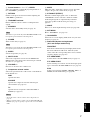
CONTROLS AND FUNCTIONS
6
This section describes the function of each control on the remote control used to control this unit. To operate other
components, see “REMOTE CONTROL FEATURES” on page 92.
The operation mode of the remote control buttons in the shaded area below depends on the component selector switch position. Set the
component selector switch to AMP to control this unit. To control the TUNER functions, set the component selector switch to SOURCE
and then press TUNER to select “TUNER” as the input source.
■ Controlling this unit
Set the component selector switch to AMP to control this
unit.
1 Infrared window
Outputs infrared control signals. Aim this window at the
component you want to operate (see page 8).
2 CODE SET
Use to set up remote control codes (see page 94).
3 Input selector buttons
Select the input source you want to control.
The corresponding input selector button for the currently selected
input source lights up for approximately 5 seconds after you press
any buttons on the remote control, showing which source
component is currently being operated.
4 Sound field program selector buttons
Select sound field programs (see page 63).
– Use SELECT to play back 2-channel sources in
surround (see page 49).
– Use EXTD SUR. to switch between 5.1 and
6.1/7.1-channel playback of multi-channel sources
(see page 48).
– Use PURE DIRECT to turn on or off the Pure Direct
mode (see page 45).
5 SPEAKERS
Turns on or off the set of front speakers connected to the
FRONT A and/or B terminals on the rear panel. Press this
button repeatedly to toggle as follows:
6 ENHANCER
Turns on or off the Compressed Music Enhancer mode
(see page 43).
7 LEVEL
Selects the speaker channel to be adjusted and sets the
output level (see page 42).
Remote control
Note
TV MUTE TV INPUT
MUTE
AMP
SOURCE
TV
MENUTITLE
SET MENU
LEVEL
DISPLAYRETURN
BAND
A/B/C/D/E
ENTER
PRESET/CH
REC
AUDIO
DISC SKIP
STEREO
1
EFFECT
VOLUME
TV VOL TV CH
TRANSMITCODE SET
STANDBY
POWER
POWERPOWER
CD
AVTV
MULTI CH IN
SLEEP
CD-R
DVD DTV
MD
CBL
TUNER
V-AUX DVR
STANDARD
5
SPEAKERS
9
MUSIC
2
SELECT
6
0
ENTERTAIN
3
EXTD SUR.
7
NIGHT
10
MOVIE
4
PURE DIRECT
8
STRAIGHT
ENT.
VCR
PHONO
ON SCREEN
ENHANCER
FREQ/TEXT EONSTARTPTY SEEKMODE
0
A
B
C
D
F
E
G
H
J
1
2
3
4
5
6
8
9
7
I
L
K
Note
A on B on
A and B off

CONTROLS AND FUNCTIONS
7
INTRODUCTION
English
8 Cursor buttons u / d / j / i, ENTER
Select and adjust the sound field program parameters or
the “SET MENU” parameters.
9 RETURN
Returns to the previous menu level when adjusting the
“SET MENU” parameters.
0 TRANSMIT indicator
Flashes while the remote control is sending infrared
signals.
A STANDBY
Sets this unit to the standby mode (see page 31).
This button is operational only when MASTER ON/OFF on the
front panel is pressed inward to the ON position.
B POWER
Turns on this unit (see page 31).
This button is operational only when MASTER ON/OFF on the
front panel is pressed inward to the ON position.
C SLEEP
Sets the sleep timer (see page 41).
D MULTI CH IN
Selects the component connected to the MULTI CH
INPUT jacks as the input source when using an external
decoder, etc. (see page 44).
E VOLUME +/–
Increases or decreases the volume level.
F Component selector switch
Selects the operation mode of the remote control buttons
in the shaded area.
AMP
Operates this unit.
SOURCE
Operates the component selected with an input
selector button (see page 93).
TV
Operates the TV assigned to either DTV/CBL or
PHONO (see page 92).
• To set the remote control codes for other components, see
page 94.
• When you set the remote control codes for both DTV/CBL and
PHONO (see page 94), priority is given to the one set for DTV/
CBL.
G MUTE
Mutes the audio output. Press again to restore the audio
output to the previous volume level (see page 40).
H STRAIGHT (EFFECT)
Turns the sound field programs off or on. When the
“STRAIGHT” mode is selected, 2-channel or multi-
channel input signals are output directly from their
respective speakers without effect processing (see
page 45).
I NIGHT
Turns on or off the night listening modes (see page 40).
J SET MENU
Enters “SET MENU” (see page 78).
K ON SCREEN
Selects the on-screen display (OSD) mode for your video
monitor (see page 47).
L Radio Data System tuning buttons
(U.K. and Europe models only)
FREQ/TEXT
Switches the Radio Data System display between the
PS mode, PTY mode, RT mode, CT mode (if the
station offers the corresponding data services) and the
frequency display (see page 61).
PTY SEEK MODE
Sets this unit to the PTY SEEK mode (see page 59).
PTY SEEK START
Starts searching for a station once the desired program
type is selected in the PTY SEEK mode (see page 59).
EON
Selects a program type (NEWS, AFFAIRS, INFO, or
SPORT) for automatic tuning (see page 60).
Note
Note
Notes

CONTROLS AND FUNCTIONS
8
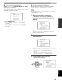
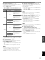
■ Controlling the TUNER functions
Set the component selector switch to SOURCE and then
press TUNER to select “TUNER” as the input source.
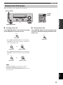
4 Numeric buttons
Use numbers 1 through 8 to select preset stations.
7 BAND
Switches the reception band between FM and AM
(see page 52).
8 Cursor buttons u / d / j / i
Press j / i to select a preset station group (A to E) and
u / d to select a preset station number (1 to 8)
(see page 56).
■ Using the remote control
The remote control transmits a directional infrared ray.
Be sure to aim the remote control directly at the remote
control sensor on this unit during operation.
• Do not spill water or other liquids on the remote control.
• Do not drop the remote control.
• Do not leave or store the remote control in the following types
of conditions:
– places of high humidity, such as near a bath
– places of high temperatures, such as near a heater or stove
– places of extremely low temperatures
– dusty places
Notes
ZONE 2
ON/OFF
ZONE
CONTROL
NEXTEDIT
EFFECT
MEMORY
FM/AM
PRESET/TUNING
A/B/C/D/E
PROGRAM
l PRESET/TUNING h
TUNING MODE
INPUT MODETONE CONTROLSTRAIGHT
SPEAKERSPHONES
MAIN ZONE
MASTER
SILENT CINEMA
BA
MULTI CH
INPUT
VOLUME
INPUT
ON OFF
LEVEL
MAN'L/AUTO FM
AUTO/MAN'L
OPTIMIZER MIC
PURE DIRECT
S VIDEO VIDEO OPTICALL AUDIO R
VIDEO AUX
ON/OFF
30 30
TV MUTE TV INPUT
MUTE
AMP
SOURCE
TV
MENUTITLE
SET MENU
LEVEL
DISPLAYRETURN
BAND
A/B/C/D/E
ENTER
PRESET/CH
REC
AUDIO
DISC SKIP
STEREO
1
EFFECT
VOLUME
TV VOL TV CH
TRANSMITCODE SET
STANDBY
POWER
POWERPOWER
CD
AVTV
MULTI CH IN
SLEEP
CD-R
DVD DTV
MD
CBL
TUNER
V-AUX DVR
STANDARD
5
SPEAKERS
9
MUSIC
2
SELECT
6
ENHANCER
0
ENTERTAIN
3
EXTD SUR.
7
NIGHT
10
MOVIE
4
PURE DIRECT
8
STRAIGHT
ENT.
VCR
PHONO
ON SCREEN
FREQ/TEXT MODE
PTY SEEK
START
EON
Approximately 6 m

CONTROLS AND FUNCTIONS
9
INTRODUCTION
English
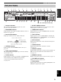
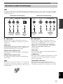
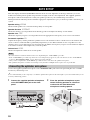
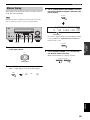
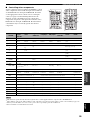
1 Decoder indicators
The respective indicator lights up when any of the
decoders of this unit function.
2 ENHANCER indicator
Lights up when the Compressed Music Enhancer mode is
turned on (see page 43).
3 Sound field indicators
Light up to indicate the active DSP sound fields.
4 VIRTUAL indicator
Lights up when Virtual CINEMA DSP is active (see
page 50).
5 Input source indicators
The corresponding cursor lights up to show the currently
selected input source.
6 DOCK indicator
Lights up when you station your iPod in a YAMAHA iPod
universal dock (such as YDS-10 sold separately)
connected to the DOCK terminal of this unit
(see page 24).
7 SILENT CINEMA indicator
Lights up when headphones are connected and a sound
field program is selected (see page 40).
8 CINEMA DSP indicator
Lights up when you select a CINEMA DSP sound field
program (see page 64).
9 YPAO indicator
Lights up when you run “AUTO SETUP” and when the
speaker settings set in “AUTO SETUP” are used without
any modifications (see page 32).
0 AUTO indicator
Lights up when this unit is in the automatic tuning mode
(see page 52).
A TUNED indicator
Lights up when this unit is tuned into a station
(see page 52).
B STEREO indicator
Lights up when this unit is receiving a strong signal for an
FM stereo broadcast while the AUTO indicator is lit
(see page 52).
C MEMORY indicator
Flashes to show that a station can be stored (see page 54).
D VOLUME level indicator
Indicates the current volume level.
E PCM indicator
Lights up when this unit is reproducing PCM (Pulse Code
Modulation) digital audio signals.
Front panel display
p
VCR
p
DVR
p
DVD
p
CD
p
V-AUX
p
DTV/CBL
p
MD/CD-R
p
TUNER
p
PHONO
96
24
q PL
q EX
q PL
ENHANCER
MATRIX DISCRETE
SILENT CINEMA
ZONE2 NIGHT
DOCK
STANDARD
AUTO
YPAO
PSHOLD RT
EON
PTYPTY
TUNED
MUTE
VOLUME
MEMORY
SLEEP
VIRTUAL
PCM
q PL x
A B
SP
mS
ft
dB
96/24
HiFi DSP
LFE
LCR
SL SB SR
q
DIGITAL
t
dB
STEREO
CT
2
H
EI
GJKL NMPO
R
D
F
1345 768 B
0A9C
Q
(U.K. and Europe models only)
Presence DSP sound field
Listening position
Surround left
DSP sound field
Surround right
DSP sound field
Surround back DSP sound field

CONTROLS AND FUNCTIONS
10
F STANDARD indicator
Lights up when the “SUR. STANDARD” or “SUR.
ENHANCED” program is selected (see page 49).
G SP A B indicators
Light up according to the set of front speakers selected.
H Headphones indicator
Lights up when headphones are connected (see page 40).
I ZONE2 indicator
Lights up when Zone 2 is turned on (see page 99).
J NIGHT indicator
Lights up when you select a night listening mode
(see page 40).
K HiFi DSP indicator
Lights up when you select a HiFi DSP sound field
program (see page 64).
L Multi-information display
Shows the name of the current sound field program and
other information when adjusting or changing settings.
M SLEEP indicator
Lights up while the sleep timer is on (see page 41).
N MUTE indicator
Flashes while the MUTE function is on (see page 40).
O 96/24 indicator
Lights up when a DTS 96/24 signal is input to this unit.
P Input channel and speaker indicators
Input channel indicators
Indicate the channel components of the current digital
input signal.
Presence and surround back speaker
indicators
Light up according to the number of presence and
surround back speakers set for “PRESENCE SP” (see
page 80) and “SUR. B L/R SP” (see page 80) in
“SOUND MENU” when “TEST” in “SOUND
MENU” is set to “ON” (see page 83).
y
You can make settings for the presence and surround back
speakers automatically by running “AUTO SETUP” (see
page 32) or manually by adjusting settings for “PRESENCE SP”
(see page 80) and “SUR. B L/R SP” (see page 80) in “SOUND
MENU”.
Q LFE indicator
Lights up when the input signal contains the LFE signal.
R Radio Data System indicators
(U.K. and Europe models only)
Lights up when the Radio Data System data is being
received.
EON
Lights up when the EON data service is being
received.
PTY HOLD
Lights up while searching for the Radio Data System
stations in the PTY SEEK mode.
LL C R
SL SB SR
Presence speaker indicator
Input channel indicator
Surround back speaker indicator

CONTROLS AND FUNCTIONS
11
INTRODUCTION
English
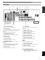
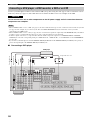
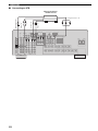
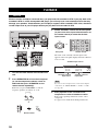
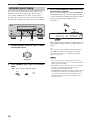
1 Audio component jacks
See page 23 for connection information.
2 DOCK terminal
Use to connect a YAMAHA iPod universal dock (such as
YDS-10 sold separately) where your iPod can be
stationed.
See page 24 for connection information.
3 COMPONENT VIDEO jacks
See pages 19 and 20 for connection information.
4 REMOTE jacks
See page 97 for details.
5 Antenna terminals
See page 28 for connection information.
6 CONTROL OUT jack
This is a control expansion terminal for custom
installation.
7 PRESENCE/ZONE2 speaker terminals
See page 15 for connection information.
8 PRE OUT jacks
See page 25 for connection information.
9 AC OUTLET(S)
Use to supply power to your other audiovisual
components.
See page 29 for details.
0 DIGITAL OUTPUT jack
See page 23 for connection information.
A DIGITAL INPUT jacks
See page 20 for connection information.
B MULTI CH INPUT jacks
See page 26 for connection information.
C ZONE 2 OUTPUT jacks
See page 97 for connection information.
These jacks output analog signals only.
D Video component jacks
See pages 19 and 20 for connection information.
E Speaker terminals
See page 13 for connection information.
■ VOLTAGE SELECTOR
(Asia and General models only)
See page 29 for details.
Rear panel
AUDIO AUDIO
DIGITAL
INPUT
DVD
DVD
CD
COAXIAL
DTV/CBL
MD/CD-R
MD/CD-R
SUB
WOOFER
SURROUND
BACK
SURROUND
FRONT
OUT
(REC)
IN
(PLAY)
MD/
CD-R
CD
DVD
VIDEO
75Ω UNBAL.
FM
ANT
AM
ANTGND
TUNER
DTV/
CBL
IN
DVR
OUT
IN
VCR
OUT
CENTER
DIGITAL OUTPUT
MULTI CH INPUT
ZONE 2
OUTPUT
VIDEOS VIDEO
MONITOR OUT
FRONT
A
B
PRESENCE/ZONE2
SPEAKERS
SURROUND
CENTER
SURROUND BACK
FRONT
SUBWOOFER
CENTER
SINGLE
PRE OUT
SURROUND
SURROUND BACK
OPTICAL
DOCK
OUTIN
REMOTE
CONTROL
OUT
+12V
15mA MAX.
MONITOR OUT
DTV/
CBL
DVD
COMPONENT VIDEO
P
R
P
B
Y
DVR
PHONO
GND
E
7
8
6
54
3
2
1
D
C
B
A0
9
Note

CONNECTIONS
12
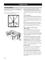
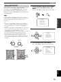
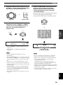
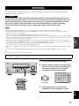
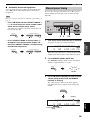
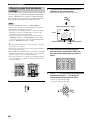
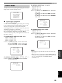
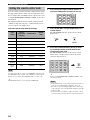
The speaker layout below shows the standard ITU-R
*
speaker setting. You can use it to enjoy CINEMA DSP and
multi-channel audio sources.
*
ITU-R is the radio communication sector of the ITU
(International Telecommunication Union).
Front left and right speakers (FL and FR)
The front speakers are used for the main source sound plus
effect sounds. Place these speakers at an equal distance
from the ideal listening position. The distance of each
speaker from each side of the video monitor should be the
same.
Center speaker (C)
The center speaker is for the center channel sounds
(dialog, vocals, etc.). If for some reason it is not practical
to use a center speaker, you can do without it. Best results,
however, are obtained with the full system. Place the
center speaker centrally between the front speakers and as
close to the monitor as possible, such as directly over or
under it.
Surround left and right speakers (SL and SR)
The surround speakers are used for effect and surround
sounds. Place these speakers behind your listening
position, facing slightly inwards, about 1.8 m above the
floor.
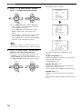
Surround back left and right speakers
(SBL and SBR)
The surround back speakers supplement the surround
speakers and provides more realistic front-to-back
transitions. Place these speakers directly behind the
listening position and at the same height as the surround
speakers. They should be positioned at least 30 cm apart.
Ideally, they should be positioned at the same width as that
of the front speakers.
Presence left and right speakers (PL and PR)
The presence speakers supplement the sound from the
front speakers with extra ambient effects produced by
CINEMA DSP (see page 64). These effects include
sounds that filmmakers intent to locate a little farther back
behind the screen in order to create more theater-like
ambience. Place these speakers at the front of the room
about 0.5 – 1 m outside the front speakers, facing slightly
inward, and about 1.8 m above the floor.
Subwoofer (SW)
The use of a subwoofer with a built-in amplifier, such as
the YAMAHA Active Servo Processing Subwoofer
System, is effective not only for reinforcing bass
frequencies from any or all channels, but also for hi-fi
stereo sound reproduction of the LFE (low-frequency
effect) channel included in Dolby Digital and DTS
sources. The position of the subwoofer is not so critical,
because low bass sounds are not highly directional. But it
is better to place the subwoofer near the front speakers.
Turn it slightly toward the center of the room to reduce
wall reflections.
CONNECTIONS
Placing speakers
SW
FR
PR
PL
FL
SBR
SBL
SL
SR
C
60˚
30˚
PL
PR
SBR
SBL
FL
FR
C
SL
SR
SR
80˚
SL
1.8 m
30 cm (12 in) or more

13
CONNECTIONS
PREPARATION
English
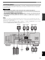
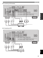
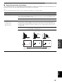
Be sure to connect the left channel (L), right channel (R), “+” (red) and “–” (black) properly. If the connections are faulty,
no sound will be heard from the speakers, and if the polarity of the speaker connections is incorrect, the sound will be
unnatural and lack bass.
• Before connecting the speakers, make sure that this unit is turned off (see page 31).
• Do not let the bare speaker wires touch each other or do not let them touch any metal part of this
unit. This could damage this unit and/or speakers.
• Use magnetically shielded speakers. If this type of speakers still creates the interference with the
monitor, place the speakers away from the monitor.
• If you are to use 4 or 6 ohm speakers, be sure to set “SP IMP.” to “6ΩMIN” before using this unit
(see page 30).
• A speaker cord is actually a pair of insulated cables running side by side. Cables are colored or shaped differently, perhaps with a
stripe, groove or ridge. Connect the striped (grooved, etc.) cable to the “+” (red) terminals of this unit and your speaker. Connect the
plain cable to the “–” (black) terminals.
• The low-frequency signals of other speakers set to “SML” (or “SMALL”) or to “NONE” in “SPEAKER SET” (see pages 79 and 80)
are directed to the speakers selected in “LFE/BASS OUT” (see page 81).
• You can use the PRESENCE/ZONE2 terminals to connect the Zone 2 speakers (see page 98).
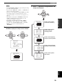
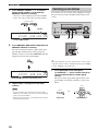
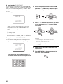
Connecting speakers
Notes
CAUTION
FRONT
A
B
PRESENCE/ZONE2
SPEAKERS
SURROUND
CENTER
SURROUND BACK
SUBWOOFER
PRE OUT
23
1
6 7 10
98
4 5
Subwoofer
Center
speaker
Front speakers (A)
Surround back
speakers
LeftRight
LeftRight
Surround speakers
Front
speakers
(B)
LeftRight
Presence speakers
LeftRight

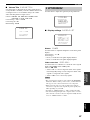
14
CONNECTIONS
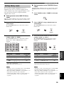
FRONT terminals
Connect one or two front speaker systems (6, 7) to these
terminals. If you use only one front speaker system,
connect it to the FRONT A or B terminal.
CENTER terminals
Connect a center speaker (8) to these terminals.
SURROUND terminals
Connect surround speakers (4, 5) to these terminals.
SURROUND BACK terminals
Connect a surround back speakers (9, 10) to these
terminals.
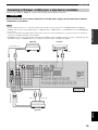
PRESENCE/ZONE2 terminals
Connect presence speakers (2, 3) to these terminals.
SUBWOOFER jack
Connect a subwoofer with a built-in amplifier (1) (such as
the YAMAHA Active Servo Processing Subwoofer
System) to this jack.
1
6
2
3
7
9
10
5
4
8
Speaker layout

15
CONNECTIONS
PREPARATION
English
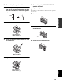
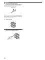
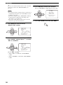
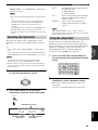
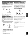
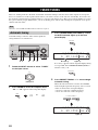
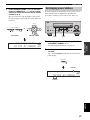
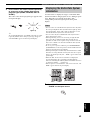
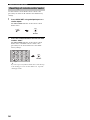
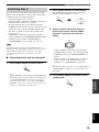
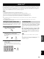
■ Connecting the speaker cable
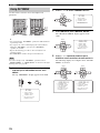
1 Remove approximately 10 mm of insulation
from the end of each speaker cable and then
twist the exposed wires of the cable together
to prevent short circuits.
2 Loosen the knob.
3 Insert one bare wire into the hole on the side
of each terminal.
4 Tighten the knob to secure the wire.
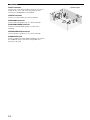
■ Connecting to the PRESENCE/ZONE2
speaker terminals
Connect presence speakers to these terminals.
y
You can also use these terminals to connect the Zone 2 speakers
(see page 97).
1 Open the tab.
2 Insert one bare wire into the hole on the side
of each terminal.
3 Close the tab to secure the wire.
10 mm
Red: positive (+)
Black: negative (–)
Red: positive (+)
Black: negative (–)
Red: positive (+)
Black: negative (–)

16
CONNECTIONS
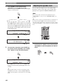
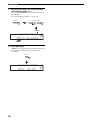
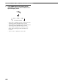
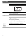
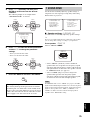
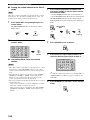
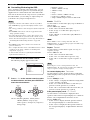
■ Connecting the banana plug
(except U.K., Europe and Asia models)
The banana plug is a single-pole electrical connector
widely used to terminate speaker cables.
y
You can also use the banana plug with the PRESENCE/ZONE2
speaker terminals. Open the tab and then insert one banana plug
into the hole on the side of each terminal. Do not close the tab
after connecting the banana plug.
1 Tighten the knob.
2 Insert the banana plug connector into the
end of the corresponding terminal.
Banana plug

17
CONNECTIONS
PREPARATION
English
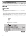
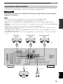
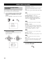
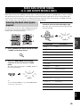
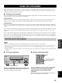
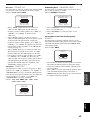
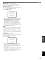
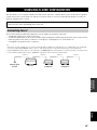
You can use the digital jacks to input PCM, Dolby Digital and DTS bitstreams. When you connect components to both the COAXIAL
and OPTICAL jacks, priority is given to the signals input at the COAXIAL jack. All digital input jacks are compatible with 96-kHz
sampling digital signals.
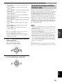
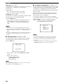
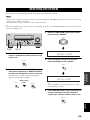
■ Audio jacks
This unit has three types of audio jacks. Connection
depends on the availability of audio jacks on your other
components.
AUDIO jacks
For conventional analog audio signals transmitted via left
and right analog audio cables. Connect red plugs to the
right jacks and white plugs to the left jacks.
DIGITAL AUDIO COAXIAL jacks
For digital audio signals transmitted via coaxial digital
audio cables.
DIGITAL AUDIO OPTICAL jacks
For digital audio signals transmitted via optical digital
audio cables.
Pull out the cap from the optical jack before you connect the fiber
optic cable. Do not discard the cap. When you are not using the
optical jack, be sure to put the cap back in place. This cap protects
the jack from dust.
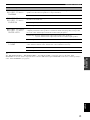
■ Video jacks
This unit has three types of video jacks. Connection
depends on the availability of input jacks on your video
monitor. When “VIDEO CONV.” is set to “ON” (see
page 87), the video signals input at the VIDEO and S
VIDEO jacks are converted and output at the VIDEO, S
VIDEO and COMPONENT VIDEO jacks
interchangeably.
VIDEO jacks
For conventional composite video signals transmitted via
composite video cables.
S VIDEO jacks
For S-video signals, separated into the luminance (Y) and
chrominance (C) video signals transmitted on separate
wires of S-video cables.
COMPONENT VIDEO jacks
For component video signals, separated into the
luminance (Y) and chrominance (P
B, PR) video signals
transmitted on separate wires of component video cables.
Information on jacks and cable plugs
Note
VIDEO S VIDEO
COMPONENT VIDEO
Y PB PR
PB
Y
P
R
S
V
COAXIAL
DIGITAL AUDIO
AUDIO
OPTICAL
DIGITAL AUDIO
R
L
C
O
R
L
Left and right
analog audio
cable plugs
Optical
digital
audio cable
plug
Coaxial
digital audio
cable plug
Composite
video cable
plug
S-video
cable plug
Component
video cable
plugs
Audio jacks and cable plugs Video jacks and cable plugs
(Red)(White) (Orange) (Yellow) (Green) (Blue) (Red)
Note

18
CONNECTIONS
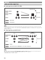
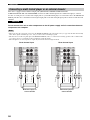
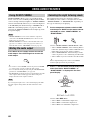
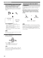
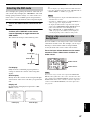
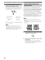
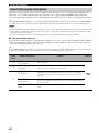
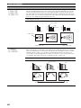
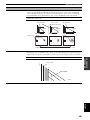
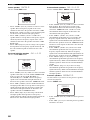
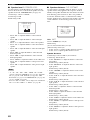
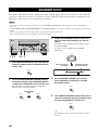
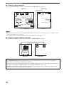
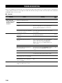
■ Audio signal flow for AUDIO OUT (REC)
This unit handles digital and analog signals independently. Thus, audio signals input at the analog jacks are output only at the analog
AUDIO OUT (REC) jacks. Likewise, audio signals input at the DIGITAL INPUT (OPTICAL or COAXIAL) jacks are output only at the
DIGITAL OUTPUT jack.
■ Video signal flow for MONITOR OUT
When video signals are input at the COMPONENT VIDEO, S VIDEO and VIDEO jacks, the priority order of the input signals is as
follows where the video signals input at the COMPONENT VIDEO jacks have the top priority:
COMPONENT VIDEO > S VIDEO > VIDEO
Audio and video signal flow
Note
Note
DIGITAL AUDIO
OPTICAL
DIGITAL AUDIO
COAXIAL
AUDIO
RLRL
Digital output
Output
AUDIO OUT (REC)
Input
Analog output
Digital audio
Analog audio
S VIDEO
VIDEO
COMPONENT
VIDEO
Y P
B
P
R
Y P
B
P
R
Through
Output
(MONITOR OUT)
Input
Video conversion when “VIDEO CONV.” is set to “ON” (see page 87)
Analog video
Seite laden ...
Seite laden ...
Seite laden ...
Seite laden ...
Seite laden ...
Seite laden ...
Seite laden ...
Seite laden ...
Seite laden ...
Seite laden ...
Seite laden ...
Seite laden ...
Seite laden ...
Seite laden ...
Seite laden ...
Seite laden ...
Seite laden ...
Seite laden ...
Seite laden ...
Seite laden ...
Seite laden ...
Seite laden ...
Seite laden ...
Seite laden ...
Seite laden ...
Seite laden ...
Seite laden ...
Seite laden ...
Seite laden ...
Seite laden ...
Seite laden ...
Seite laden ...
Seite laden ...
Seite laden ...
Seite laden ...
Seite laden ...
Seite laden ...
Seite laden ...
Seite laden ...
Seite laden ...
Seite laden ...
Seite laden ...
Seite laden ...
Seite laden ...
Seite laden ...
Seite laden ...
Seite laden ...
Seite laden ...
Seite laden ...
Seite laden ...
Seite laden ...
Seite laden ...
Seite laden ...
Seite laden ...
Seite laden ...
Seite laden ...
Seite laden ...
Seite laden ...
Seite laden ...
Seite laden ...
Seite laden ...
Seite laden ...
Seite laden ...
Seite laden ...
Seite laden ...
Seite laden ...
Seite laden ...
Seite laden ...
Seite laden ...
Seite laden ...
Seite laden ...
Seite laden ...
Seite laden ...
Seite laden ...
Seite laden ...
Seite laden ...
Seite laden ...
Seite laden ...
Seite laden ...
Seite laden ...
Seite laden ...
Seite laden ...
Seite laden ...
Seite laden ...
Seite laden ...
Seite laden ...
Seite laden ...
Seite laden ...
Seite laden ...
Seite laden ...
Seite laden ...
Seite laden ...
Seite laden ...
Seite laden ...
Seite laden ...
Seite laden ...
Seite laden ...
Seite laden ...
Seite laden ...
Seite laden ...
Seite laden ...
Seite laden ...
Seite laden ...
Seite laden ...
Seite laden ...
Seite laden ...
Seite laden ...
Seite laden ...
-
 1
1
-
 2
2
-
 3
3
-
 4
4
-
 5
5
-
 6
6
-
 7
7
-
 8
8
-
 9
9
-
 10
10
-
 11
11
-
 12
12
-
 13
13
-
 14
14
-
 15
15
-
 16
16
-
 17
17
-
 18
18
-
 19
19
-
 20
20
-
 21
21
-
 22
22
-
 23
23
-
 24
24
-
 25
25
-
 26
26
-
 27
27
-
 28
28
-
 29
29
-
 30
30
-
 31
31
-
 32
32
-
 33
33
-
 34
34
-
 35
35
-
 36
36
-
 37
37
-
 38
38
-
 39
39
-
 40
40
-
 41
41
-
 42
42
-
 43
43
-
 44
44
-
 45
45
-
 46
46
-
 47
47
-
 48
48
-
 49
49
-
 50
50
-
 51
51
-
 52
52
-
 53
53
-
 54
54
-
 55
55
-
 56
56
-
 57
57
-
 58
58
-
 59
59
-
 60
60
-
 61
61
-
 62
62
-
 63
63
-
 64
64
-
 65
65
-
 66
66
-
 67
67
-
 68
68
-
 69
69
-
 70
70
-
 71
71
-
 72
72
-
 73
73
-
 74
74
-
 75
75
-
 76
76
-
 77
77
-
 78
78
-
 79
79
-
 80
80
-
 81
81
-
 82
82
-
 83
83
-
 84
84
-
 85
85
-
 86
86
-
 87
87
-
 88
88
-
 89
89
-
 90
90
-
 91
91
-
 92
92
-
 93
93
-
 94
94
-
 95
95
-
 96
96
-
 97
97
-
 98
98
-
 99
99
-
 100
100
-
 101
101
-
 102
102
-
 103
103
-
 104
104
-
 105
105
-
 106
106
-
 107
107
-
 108
108
-
 109
109
-
 110
110
-
 111
111
-
 112
112
-
 113
113
-
 114
114
-
 115
115
-
 116
116
-
 117
117
-
 118
118
-
 119
119
-
 120
120
-
 121
121
-
 122
122
-
 123
123
-
 124
124
-
 125
125
-
 126
126
-
 127
127
-
 128
128


Yamaha RX-V659 Bedienungsanleitung
- Kategorie
- AV-Receiver
- Typ
- Bedienungsanleitung
in anderen Sprachen
- English: Yamaha RX-V659 Owner's manual
- français: Yamaha RX-V659 Le manuel du propriétaire
- italiano: Yamaha RX-V659 Manuale del proprietario
- Nederlands: Yamaha RX-V659 de handleiding
- dansk: Yamaha RX-V659 Brugervejledning
- svenska: Yamaha RX-V659 Bruksanvisning
- Türkçe: Yamaha RX-V659 El kitabı
- română: Yamaha RX-V659 Manualul proprietarului
Verwandte Papiere
-
Yamaha RX-797 Bedienungsanleitung
-
-
-
-
Yamaha HTR-N5060 Bedienungsanleitung
-
-
-
Yamaha RX-V863 Bedienungsanleitung
-
-