
Ausgabe/Edition:
06.2018
Änderungsindex
Rev. index: 01.0
Printed in Germany
1 Komponenten des Bausatzes
Bevor Sie mit dem Einbau beginnen:
Bitte überprüfen Sie, ob alle Bauteile des Teilesatzes in dem
Lieferumfang enthalten sind.
Der Teilesatz 0867 590984 besteht aus folgenden Komponenten.
Bauteil Teilenummer
1 x Fadenführung 0667 115743
2 x Senkschraube 9225 201770
1 x O-Ring 0911 000290
1 x Buchse 0667 115730
1 x Hubmagnet 9820 110025
2 Umbau
Vorsicht Verletzungsgefahr!
Schalten Sie den Hauptschalter aus und ziehen Sie den Netzstecker,
bevor sie mit dem Einbau beginnen.
Der Einbau darf nur von qualifizierten Technikern durchgeführt
werden.
Anbauanleitung für Teilesatz Fadenklemme
0867 590984
Fitting Instruction for the Kit Thread Clamp
0867 590984
Teile-Nr./ Part-No.:
0791 867773
Blatt: von
Sheet: 1 from 12

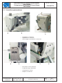
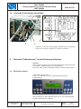
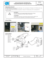
2.1 Fadenführung demontieren
– Armdeckel 1 entfernen
– Kopfdeckel 2 entfernen.
– Rückseitigen Ventildeckel 3 entfer nen.
– Schrauben 4 herausdrehen.
– Fadenführung 5 abnehmen.
–
Gewindestift 7 lösen.
–
Stopfen 6 entfernen.
Anbauanleitung für Teilesatz Fadenklemme
0867 590984
Fitting Instruction for the Kit Thread Clamp
0867 590984
Teile-Nr./ Part-No.:
0791 867773
Blatt: von
Sheet: 2 from 12
Ausgabe/Edition:
06.2018
Änderungsindex
Rev. index: 01.0
Printed in Germany
21
3
54
76

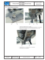
2.2 Fadenklemme montieren
– O-Ring 2 auf die Buchse 1 legen.
– Neue Fadenführung 4 mit den beiden Schrauben 3 montieren.
– Buchse 1 so einsetzen, dass die Fläche der Buchse zum
Gewindestift 6 zeigt.
– Fadenklemme5indieBuchse1einsetzen.
– Gewindestift 6 festdrehen.
Anbauanleitung für Teilesatz Fadenklemme
0867 590984
Fitting Instruction for the Kit Thread Clamp
0867 590984
Teile-Nr./ Part-No.:
0791 867773
Blatt: von
Sheet: 3 from 12
Ausgabe/Edition:
06.2018
Änderungsindex
Rev. index: 01.0
Printed in Germany
21 413
65

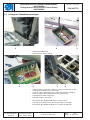
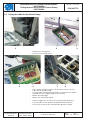
2.3 Leitung der Fadenklemme verlegen
– Nähfüße demontieren.
– Nähleuchte 1 abschrauben.
– In den Ecken 2 und 3 des Deckels 1 eine Aussparung für die
Leitung der Fadenklemme herstellen.
– Leitung 4 der Fadenklemme so in der Leiterplatte verlegen,
dass sie neben den Lötspitzen 5 der Platine liegt.
– Leiterplatte wieder montieren.
– Nähfüße wieder montieren.
–
Schrauben des Bedienfeldhalters 7 etwas lösen.
–
Leitung der Fadenklemme hinter die Halter 6 verlegen.
–
Schrauben des Bedienfeldhalters 7 wieder festdrehen.
Anbauanleitung für Teilesatz Fadenklemme
0867 590984
Fitting Instruction for the Kit Thread Clamp
0867 590984
Teile-Nr./ Part-No.:
0791 867773
Blatt: von
Sheet: 4 from 12
Ausgabe/Edition:
06.2018
Änderungsindex
Rev. index: 01.0
Printed in Germany
1
32
54
76

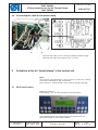
2.4 Leitung der Fadenklemme anschließen
– Leitung 1 an Klemme 6 (Ausgang Fadenklemme) anschließen.
– Leitung 2 an Klemme 7 oder 8 (++24V) anschließen.
3 Teilesatz “Fadenklemme” in der Steuerung aktivieren
Anbauanleitung für Teilesatz Fadenklemme
0867 590984
Fitting Instruction for the Kit Thread Clamp
0867 590984
Teile-Nr./ Part-No.:
0791 867773
Blatt: von
Sheet: 5 from 12
Ausgabe/Edition:
06.2018
Änderungsindex
Rev. index: 01.0
Printed in Germany
21
Hinweis:
Beim ersten Annähen nach dem Einschalten der Steuerung wird
die Funktion Fadenklemme nicht angesteuert.
Erst nach dem ersten Fadenabsc
hneiden ist die Funktion aktiv.
Fadenklemme aktivieren:
Taste “TC” drücken, für eine schnelle Aktivierung der
Fadenklemme.
Die Parameter für die Fadenklemme sind in der Parameterliste
der DAC basic/classic erläutert.
3.1 DAC basic/classic

Anbauanleitung für Teilesatz Fadenklemme
0867 590984
Fitting Instruction for the Kit Thread Clamp
0867 590984
Teile-Nr./ Part-No.:
0791 867773
Blatt: von
Sheet: 6 from 12
Ausgabe/Edition:
06.2018
Änderungsindex
Rev. index: 01.0
Printed in Germany
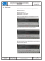
3.2 Efka Control
Diese Parameter müssen bei DA321G eingestellt werden:
Parameter 14 FW = 1
Fadenwischer ist ON.
Parameter 154 FkL = 8
Fadenklemme von 90° bis 200°.
Nähfußlüftung von 50° bis 80°.
Fadenklemme aktivieren:
Taste 5 für schnelle Aktivierung der Fadenklemme drücken
.
Zwei Pfeile müssen über Taste 5 angezeigt werden.
Taste 5 zweimal drücken, um die Fadenklemme zu deaktivieren.
E
in Pfeil über Taste 5 muss angezeigt werden, dann bleibt der
Fadenabschneider aktiviert.

Ausgabe/Edition:
06.2018
Änderungsindex
Rev. index: 01.0
Printed in Germany
1 Kit components
Before beginning the installation:
Please check whether you have all the necessary components for the
kit listed in the scope of delivery.
The kit 0867 590984 consists of the following components:
Component Parts number
1 x Thread guide 0667 115743
2 x Countersunk screw 9225 201770
1 x O ring 0911 000290
1 x Bushing 0667 115730
1 x Solenoid 9820 110025
2 Conversion
Caution: Risk of injury!
Tur n off the main switch and pull out the mains plug before
performing the conversion task.
The fitting of the kit must be carried out by qualified technicians
only.
Anbauanleitung für Teilesatz Fadenklemme
0867 590984
Fitting Instruction for the Kit Thread Clamp
0867 590984
Teile-Nr./ Part-No.:
0791 867773
Blatt: von
Sheet: 7 from 12

2.1 Removing the thread guide
– Remove the arm cover 1.
– Remove the face cover 2.
– Remove the valve cap 3 on the back.
– Loosen screws 4.
– Remove the thread guide 5.
–
Loosen the threaded pin 7.
–
Remove the cap 6.
Anbauanleitung für Teilesatz Fadenklemme
0867 590984
Fitting Instruction for the Kit Thread Clamp
0867 590984
Teile-Nr./ Part-No.:
0791 867773
Blatt: von
Sheet: 8 from 12
Ausgabe/Edition:
06.2018
Änderungsindex
Rev. index: 01.0
Printed in Germany
21
3
54
76

2.2 Mounting the thread clamp
– Put the O ring 2 on the bushing 1.
– Mount the new thread guide 4 with both screws 3.
– Insert the bushing 1 in a way that the surface of the bushing
points to the threaded pin 6.
– Insert the thread clamp 5 in the bushing 1.
– Fasten the threaded pin 6.
Anbauanleitung für Teilesatz Fadenklemme
0867 590984
Fitting Instruction for the Kit Thread Clamp
0867 590984
Teile-Nr./ Part-No.:
0791 867773
Blatt: von
Sheet: 9 from 12
Ausgabe/Edition:
06.2018
Änderungsindex
Rev. index: 01.0
Printed in Germany
21 413
65

2.3 Laying the cable for the thread clamp
– Remove the sewing feet.
– Unscrew the sewing light 1.
– File a notch on both corners 2 and 3 of the cover 1 for the
cable of the thread clamp.
– Lay the cable 4 of the thread clamp in a way that the cable is
located near the soldering tips 5 of the PCB.
– Mount the PCB again.
– Mount the sewing feet again.
–
Loosen slightly the screws of the control panel bracket 7.
–
Lay the cable of the thread clamp behind the bracket 6.
–
Fasten the screws of the control panel bracket 7 again.
Anbauanleitung für Teilesatz Fadenklemme
0867 590984
Fitting Instruction for the Kit Thread Clamp
0867 590984
Teile-Nr./ Part-No.:
0791 867773
Blatt: von
Sheet: 10 from 12
Ausgabe/Edition:
06.2018
Änderungsindex
Rev. index: 01.0
Printed in Germany
1
32
54
76

2.4 Connecting the cable for the thread clamp
– Connect the cable 1 to the clamp 6 (Output thread clamp).
– Connect the cable 2 to clamp 7 or 8 (++24V).
3 Activation of the kit “thread clamp” in the control unit
Note:
The
function “thread clamp” is not yet active at the first sewing
start after switching on the control unit.
The function is activated only after the first thread trimming.
Display activation:
Press button “TC” for fast activation of thread clamp.
The parameters for the thread clamp are explained in the
parameter sheet for DAC basic/classic.
Anbauanleitung für Teilesatz Fadenklemme
0867 590984
Fitting Instruction for the Kit Thread Clamp
0867 590984
Teile-Nr./ Part-No.:
0791 867773
Blatt: von
Sheet: 11 from 12
Ausgabe/Edition:
06.2018
Änderungsindex
Rev. index: 01.0
Printed in Germany
21
3.1 DAC basic/classic

Anbauanleitung für Teilesatz Fadenklemme
0867 590984
Fitting Instruction for the Kit Thread Clamp
0867 590984
Teile-Nr./ Part-No.:
0791 867773
Blatt: von
Sheet: 12 from 12
Ausgabe/Edition:
06.2018
Änderungsindex
Rev. index: 01.0
Printed in Germany
3.2 Efka Control
These parameters have to be set on DA321G:
Parameter 14 FW = 1
Thread wiper is ON.
Parameter 154 FkL = 8
Thead clamp from 90° to 200°.
Sewing foot lifting from 50° to 80°.
Display activation:
Press button 5 for fast activation of thread clamp.
Two arrows must be displayed above button 5.
Press button 5 twice to deactivate thread clamp.
One arrow above button 5 must be displayed, then thread
trim remains activated.
-
 1
1
-
 2
2
-
 3
3
-
 4
4
-
 5
5
-
 6
6
-
 7
7
-
 8
8
-
 9
9
-
 10
10
-
 11
11
-
 12
12


DURKOPP ADLER 867 Benutzerhandbuch
- Typ
- Benutzerhandbuch
- Dieses Handbuch eignet sich auch für
Verwandte Artikel
-
DURKOPP ADLER 550-867 s Benutzerhandbuch
-
-
Duerkopp Adler 867-M Benutzerhandbuch
-
-
 Duerkopp Adler 550-2-2 Benutzerhandbuch
-
-
-
-
-

