Viessmann 5040 Bedienungsanleitung
- Kategorie
- Kaffeezubehör
- Typ
- Bedienungsanleitung

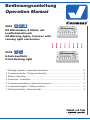
Bedienungsanleitung
Operation Manual
5040
H0 Warnbaken, 8 Stück, mit
Lauichtelektronik
H0 Warning lights, 8 pieces with
running light electronics
5539
8-fach-Lauicht
8-fold ashing light
1. Wichtige Hinweise / Important information ........................................................ 2
2. Funktionskontrolle / Testing functionality ........................................................... 2
3. Einbau / Mounting ............................................................................................. 3
4. Anschluss / Connection ..................................................................................... 3
5. Funktionsumschaltung / Speed of movement ................................................... 3
6. Laufgeschwindigkeit / Setting functions ............................................................ 3
7. Technische Daten / Technical data .................................................................... 3
AC
~
DC
=
LED
AC
~
DC
=

2
1. Wichtige Hinweise
Bitte lesen Sie vor der ersten Anwendung des Produktes
bzw. dessen Einbau diese Bedienungsanleitung aufmerk-
sam durch. Bewahren Sie diese auf, sie ist Teil des Pro-
duktes.
1.1 Sicherheitshinweise
Vorsicht:
Verletzungsgefahr!
Aufgrund der detaillierten Abbildung des Originals bzw.
der vorgesehenen Verwendung kann das Produkt Spit-
zen, Kanten und abbruchgefährdete Teile aufweisen. Für
die Montage sind Werkzeuge nötig.
Stromschlaggefahr!
Die Anschlussdrähte niemals in eine Steckdose einfüh-
ren! Verwendetes Versorgungsgerät (Transformator,
Netzteil) regelmäßig auf Schäden überprüfen. Bei Schä-
den am Versorgungsgerät dieses keinesfalls benutzen!
Alle Anschluss- und Montagearbeiten nur bei abgeschal
-
teter Betriebsspannung durchführen!
Ausschließlich nach VDE/EN-gefertigte Modellbahn-
transformatoren verwenden!
Stromquellen unbedingt so absichern, dass es bei einem
Kurzschluss nicht zum Kabelbrand kommen kann.
1.2 Das Produkt richtig verwenden
Dieses Produkt ist bestimmt:
- Zum Einbau in Modelleisenbahnanlagen und Dioramen.
- Zum Anschluss an einen Modellbahntransformator
(z. B. Art. 5200) bzw. an eine Modellbahnsteuerung mit
zugelassener Betriebsspannung.
- Zum Betrieb in trockenen Räumen.
Jeder darüber hinausgehende Gebrauch gilt als nicht be-
stimmungsgemäß. Für daraus resultierende Schäden haf-
tet der Hersteller nicht.
1.3 Packungsinhalt überprüfen
Kontrollieren Sie den Lieferumfang auf Vollständigkeit:
- 8-fach-Lauicht
- Montagematerial (12 Stecker, 2 Schrauben)
- 8 Warnbaken (nur bei Art. 5040)
- Anleitung
2. Funktionskontrolle
Alle Viessmann Artikel werden vor dem Verpacken einer
strengen Qualitätsprüfung unterzogen. Hierzu gehört auch
eine Funktionsprüfung. Da Transportschäden nie ganz aus-
geschlossen werden können, sollten Sie vor der Montage
die Funktion prüfen.
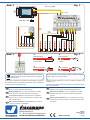
Art. 5040: Schließen dazu vor der Montage die Elektronik
und die Warnbaken probeweise gemäß Abb. 1 an. Achten
Sie dabei auf die richtige Polung der Anschlüsse.
Art. 5539: Schließen Sie die Elektronik probeweise ge-
mäß Abb. 1 an. Achten Sie dabei auf die richtige Polung
der Anschlüsse.
1. Important information
Please read this manual completely and attentively before
using the product for the rst time. Keep this manual. It is
part of the product.
1.1 Safety instructions
Caution:
Risk of injury!
Due to the detailed reproduction of the original and
the intended use, this product can have peaks, edges
and breakable parts. Tools are required for installation.
Electrical hazard!
Never put the connecting wires into a power socket!
Regularly examine the transformer for damage. In case
of any damage, do not use the transformer.
Make sure that the power supply is switched o when
you mount the device and connect the cables!
Only use VDE/EN tested special model train transform-
ers for the power supply!
The power sources must be protected to avoid the risk
of burning cables.
1.2 Using the product for its correct purpose
This product is intended:
- For installation in model train layouts and dioramas.
- For connection to an authorized model train transformer
(e. g. item 5200) or a digital command station.
- For operation in dry rooms only.
Using the product for any other purpose is not approved
and is considered inappropriate. The manufacturer is not
responsible for any damage resulting from the improper
use of this product.
1.3 Checking the package contents
Check the contents of the package for completeness:
- 8-fold ashing light
- Mounting material (12 plugs, 2 screws)
- 8 warning lights (only with item 5040)
- Manual
2. Testing functionality
All Viessmann products undergo a stringent quality tests
prior to packing including a function test. Since damage
during transit cannot always be prevented you should car-
ry out a test of the functions prior to installation.
Item 5040: Connect the electronic module and the warn-
ing boards as per g. 1 for testing. Make sure polarity is
correct.
Item 5539: Connect the module as per g. 1 and observe
correct polarity.
DE EN

3
3. Einbau
Der Elektronikbaustein kann mit den beiliegenden Schrau-
ben auf oder unter der Anlage angeschraubt werden (durch
die beiden großen Bohrungen).
Für die Befestigung der Warnbaken (Art. 5040) bohren Sie
ein Loch mit einem Durchmesser von 2,5 mm in die Anla-
genplatte. Die Baken können dann einfach eingesteckt wer
-
den.NötigenfallsxierenSiedieBakenmitetwasKlebsto.
4. Anschluss
Art. 5040: Schließen Sie die Warnbaken gemäß Abb. 1 an.
Vorsicht!
Die dem Art. 5040 beiliegenden Warnbaken dürfen
nur an die entsprechenden Ausgänge des Elektronik-
bausteines Art. 5539 angeschlossen werden.
Die Widerstände an den Anschlusskabeln der Warn-
baken dürfen nicht entfernt werden! Die LEDs werden
dadurch zerstört!
Art. 5539: Der Anschluss erfolgt sinngemäß wie bei Abb.
1. Anstelle der Warnbaken können Sie an die 8 Ausgänge
sowohl Glühlampen mit einer Nennspannung von 12 – 14
V als auch LEDs mit entsprechenden Vorwiderständen an-
schließen (siehe Kasten bei Abb. 1).
Passenden Artikel:
Glühlampen:
Art. 3500 (blau), Art. 3501 (gelb), Art. 3502 (rot), Art. 3503 (klar),
LED-Sets mit Vorwiderstand:
Ø 3 mm: Art. 3550 (rot), Art. 3551 (gelb), Art. 3552 (grün)
Ø 1,8 mm: Art. 3553 (rot), Art. 3555 (gelb), Art. 3554 (grün)
5. Laufgeschwindigkeit
Die Laufgeschwindigkeit können Sie mit Hilfe eines kleinen
Schraubendrehers einstellen (Abb. 2).
6. Funktionsumschaltung
DieViessmannLauichtelektronikhatzweiFunktionen:
Funktion A (Grundfunktion): Die Ausgänge werden nach-
einander eingeschaltet und dann zusammen ausgeschaltet.
Diese Funktion ist besonders für Lichtreklamen geeignet.
Funktion B: Die Ausgänge werden einzeln nacheinander
durchgeschaltet, d. h. es leuchtet immer nur eine Lampe
bzw. LED.
Funktion B erhalten Sie, indem Sie mittels einer Draht-/
Kabelbrücke die beiden mit B bezeichneten Buchsen ver-
binden.
7. Technische Daten
Versorgungsspannung: 14 – 16 V AC~
Stromaufnahme
(ohne Lampen bzw. LEDs): ca. 20 mA
Ausgänge 1 – 8:Max.StromproAusgang 100mA
3. Mounting
The electronic module can be fastened with the two screws
on or under the layout (through the two large holes).
For mounting the warning boards (item 5040) drill a 2,5
mm diameter hole in the baseboard. Then simply insert
the boards. Fix them with some glue if necessary.
4. Connection
Item 5040: Connect the warning boards as per g. 1.
Caution!
The warning boards supplied with item 5040 may only
be connected to the appropriate outputs of the electronic
module item 5539.
Do not remove the resistors soldered to the cables of the
warning boards! Otherwise the LEDs will be destroyed!
Item 5539: Connection is done as indicated in g. 1. In-
stead of the warning boards you connect 12 – 14 V bulbs
or LEDs with the appropriate serial resistors to the 8 out-
puts (see insert in g. 1).
Suitable items:
Bulbs:
item 3500 (blue), item 3501 (yellow), item 3502 (red), item
3503 (clear)
LED sets with serial resistors:
Ø 3 mm: item 3550 (red), item 3551 (yellow), item 3552 (green)
Ø 1.8 mm: item 3553 (red), item 3554 (green), item 3555 (yellow)
5. Speed of movement
You may adjust the speed of the running lights by means
of a small screw driver (g. 2).
6. Setting functions
The Viessmann electronic module for ashing lights has
two functions:
Function A (basic function): The outputs are switched
in series one after the other and are switched o simul-
taneously.
Function B: The outputs are individually switched one af-
ter the other, in other words only one light will be on at any
one time resp. LED.
For setting function B bridge the terminals marked B with
a piece of wire.
7. Technical data
Supply Voltage: 14 – 16 V AC~
Current consumption
(without bulbs resp. LEDs): appr. 20 mA
Outputs 1 – 8: Max. current loading 100 mA

Modellbauartikel, kein Spielzeug! Nicht geeignet für Kinder
unter 14 Jahren! Anleitung aufbewahren!
Model building item, not a toy! Not suitable for children
under the age of 14 years! Keep these instructions!
Ce n’est pas un jouet. Ne convient pas aux enfants de
moins de 14 ans ! C’est un produit décor! Conservez cette
notice d’instructions!
Não é um brinquedo!Não aconselhável para menores de
14 anos. Conservar a embalagem.
Modelbouwartikel, geen speelgoed! Niet geschikt voor
kinderen onder 14 jaar! Gebruiksaanwijzing bewaren!
Articolo di modellismo, non è un giocattolo! Non adatto
a bambini al di sotto dei 14 anni! Conservare instruzioni
per l’uso!
Artículo para modelismo ¡No es un juguete! No recomen-
dado para menores de 14 años! Conserva las instrucciones
de servicio!
DE
EN
FR
NL
IT
ES
PT
Modelltechnik GmbH
Bahnhofstraße 2a
D - 35116 Hatzfeld-Reddighausen
www.viessmann-modell.de
Made in Europe
Stecker aufschieben
insert the plug
Draht umbiegen
bend the wire
Litzen verdrillen
twist the wires
together
Kabel abisolieren
strip the insulation
from the cable
ca. 1,5 cm
1.
2.
3.
4.
Sekundär
0-10-16 V~
16 V
Primär
230 V~
Gefertigt nach
VDE 0570
EN 61558
Lichttransformator
5200
Nur für trockene Räume
Primär 230 V 50 - 60 Hz
Sekundär max. 3,25 A52 VA
ta 25°CIP 40
10 V
0 V
z. B. / e. g. 5200
max. 16 V ~ AC
gelb
yellow
braun
brown
gelb / yellow
braun / brown
gelb
yellow
braun
brown
LEDs
Fig. 1
Abb. 1
Fig. 1
Abb. 1
Änderungen vorbehalten. Keine Haftung für Druckfehler und Irrtümer.
DieaktuelleVersionderAnleitungndenSieaufderViessmann
Homepage unter der Artikelnummer.
Subject to change without prior notice. No liability for mistakes and
printing errors.
You will nd the latest version of the manual on the Viessmann web-
site using the item-No.
98335
Stand 04/sw
12/2018
Ho/Ir
Entsorgen Sie dieses Produkt nicht über den (unsor-
tierten) Hausmüll, sondern führen Sie es der Wieder-
verwertung zu.
Do not dispose of this product through (unsorted) domestic
waste, supply it to recycling instead.
-
 1
1
-
 2
2
-
 3
3
-
 4
4


Viessmann 5040 Bedienungsanleitung
- Kategorie
- Kaffeezubehör
- Typ
- Bedienungsanleitung
in anderen Sprachen
Verwandte Artikel
-
Viessmann 5539 Bedienungsanleitung
-
-
-
-
-
-
-
-
-