Tannoy CMS 503ICT LP Schnellstartanleitung
- Kategorie
- Autolautsprecher
- Typ
- Schnellstartanleitung

Quick Start Guide
CMS 3.0 Series
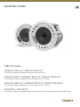
CMS803DC BM/PI/Q / CMS803 PI BACKCAN
8" Full Range Ceiling Loudspeaker with Dual Concentric Driver
CMS603DC BM/PI / CMS603ICT BM/PI/LS / CMS603 PI BACKCAN
6" Full Range Ceiling Loudspeaker with Dual Concentric or ICT Driver
CMS503DC BM/PI/LP / CMS503ICT BM/PI/LP / CMS503 PI BACKCAN
5" Full Range Ceiling Loudspeaker with Dual Concentric or ICT Driver
CMS403DCE / CMS403ICTE
4" Full Range Ceiling Loudspeaker with Dual Concentric or ICT Driver and adjustable “eyeball” design

2 CMS 3.0 Series Quick Start Guide 3
Instrucciones de
seguridad
NEGACIÓN LEGAL
GARANTÍA LIMITADA
Las terminales marcadas con este símbolo
transportan corriente eléctrica de
magnitud suciente como para constituir
un riesgo de descarga eléctrica. Utilice solo cables de
altavoz profesionales y de alta calidad con conectores
TS de 6,3 mm o de bayoneta prejados. Cualquier otra
instalación o modicación debe ser realizada únicamente
por un técnico cualicado.
Este símbolo, siempre que aparece,
leadvierte de la presencia de voltaje
peligroso sin aislar dentro de la caja;
estevoltaje puede ser suciente para constituir un riesgo
dedescarga.
Este símbolo, siempre que aparece,
leadvierte sobre instrucciones operativas
y de mantenimiento que aparecen en la
documentación adjunta. Por favor, lea el manual.
Atención
Para reducir el riesgo de descarga
eléctrica, no quite la tapa (o la parte
posterior). No hay piezas en el interior del equipo que
puedan ser reparadas por el usuario. Si es necesario,
póngase en contacto con personal cualicado.
Atención
Para reducir el riesgo de incendio o
descarga eléctrica, no exponga este
aparato a la lluvia, humedad o alguna otra fuente que
pueda salpicar o derramar algún líquido sobre el aparato.
Nocoloque ningún tipo de recipiente para líquidos sobre
el aparato.
Atención
Las instrucciones de servicio deben
llevarlas a cabo exclusivamente personal
cualicado. Para evitar el riesgo de una descarga eléctrica,
no realice reparaciones que no se encuentren descritas
en el manual de operaciones. Lasreparaciones deben ser
realizadas exclusivamente por personalcualicado.
1. Lea las instrucciones.
2. Conserve estas instrucciones.
3. Preste atención a todas las advertencias.
4. Siga todas las instrucciones.
5. No use este aparato cerca del agua.
6. Limpie este aparato con un paño seco.
7. No bloquee las aberturas de ventilación. Instale el
equipo de acuerdo con las instrucciones del fabricante.
8. No instale este equipo cerca de fuentes de calor
tales como radiadores, acumuladores de calor, estufas u
otros aparatos (incluyendo amplicadores) que puedan
producir calor.
9. No elimine o deshabilite nunca la conexión a tierra
del aparato o del cable de alimentación de corriente.
Unenchufe polarizado tiene dos polos, uno de los cuales
tiene un contacto más ancho que el otro. Una clavija con
puesta a tierra dispone de tres contactos: dos polos y la
puesta a tierra. El contacto ancho y el tercer contacto,
respectivamente, son los que garantizan una mayor
seguridad. Si el enchufe suministrado con el equipo no
concuerda con la toma de corriente, consulte con un
electricista para cambiar la toma de corriente obsoleta.
10. Coloque el cable de suministro de energía de manera
que no pueda ser pisado y que esté protegido de objetos
alados. Asegúrese de que el cable de suministro de
energía esté protegido, especialmente en la zona de la
clavija y en el punto donde sale del aparato.
11. Use únicamente los dispositivos o accesorios
especicados por el fabricante.
12. Use únicamente la
carretilla, plataforma,
trípode, soporte o mesa
especicados por el
fabricante o suministrados
junto con el equipo.
Altransportar el equipo,
tenga cuidado para evitar
daños y caídas al tropezar con algún obstáculo.
13. Desenchufe el equipo durante tormentas o si no va a
utilizarlo durante un periodo largo.
14. Confíe las reparaciones únicamente a servicios
técnicos cualicados. La unidad requiere mantenimiento
siempre que haya sufrido algún daño, si el cable de
suministro de energía o el enchufe presentaran daños,
sehubiera derramado un líquido o hubieran caído objetos
dentro del equipo, si el aparato hubiera estado expuesto
a la humedad o la lluvia, si ha dejado de funcionar de
manera normal o si ha sufrido algún golpe o caída.
15. Al conectar la unidad a la toma de corriente eléctrica
asegúrese de que la conexión disponga de una unión
atierra.
16. Si el enchufe o conector de red sirve como único
medio de desconexión, éste debe ser accesiblefácilmente.
17. Cómo debe deshacerse de
este aparato: Este símbolo indica
que este aparato no debe ser
tratado como basura orgánica,
según lo indicado en la Directiva
WEEE (2012/19/EU) y a las
normativas aplicables en su país.
En lugar de ello deberá llevarlo al punto limpio más
cercano para el reciclaje de sus elementos eléctricos/
electrónicos (EEE). Al hacer esto estará ayudando a
prevenir las posibles consecuencias negativas para el
medio ambiente y la salud que podrían ser provocadas por
una gestión inadecuada de este tipo de aparatos. Además,
el reciclaje de materiales ayudará a conservar los recursos
naturales. Para más información acerca del reciclaje de
este aparato, póngase en contacto con el Ayuntamiento
de su ciudad o con el punto limpio local.
18. No instale esta unidad en un espacio muy reducido,
tal como encastrada en una librería o similar.
19. No coloque objetos con llama, como una vela
encendida, sobre este aparato.
20. Tenga presentes todas las advertencias relativas
al reciclaje y correcta eliminación de las pilas. Las pilas
deben ser siempre eliminadas en un punto limpio y nunca
con el resto de la basura orgánica.
21. Use este aparato en rangos de temperatura
moderados y/o tropicales.
Music Tribe no admite ningún tipo de responsabilidad
por cualquier daño o pérdida que pudiera sufrir
cualquier persona por conar total o parcialmente en
la descripciones, fotografías o armaciones contenidas
en este documento. Las especicaciones técnicas,
imágenes y otras informaciones contenidas en este
documento están sujetas a modicaciones sin previo
aviso. Todas las marcas comerciales que aparecen
aquí son propiedad de sus respectivos dueños. Midas,
Klark Teknik, Lab Gruppen, Lake, Tannoy, Turbosound,
TC Electronic, TC Helicon, Behringer, Bugera y Coolaudio
son marcas comerciales o marcas registradas de
Music Tribe Global Brands Ltd. © Music Tribe Global
Brands Ltd. 2018 Reservados todos los derechos.
Si quiere conocer los detalles y condiciones aplicables
de la garantía así como información adicional sobre la
Garantía limitada de Music Tribe, consulte online toda la
información en la web musictribe.com/warranty.
Terminals marked with this symbol carry
electrical current of sucient magnitude
to constitute risk of electric shock.
Use only high-quality professional speaker cables with
¼" TS or twist-locking plugs pre-installed. Allother
installation or modication should be performed only
by qualiedpersonnel.
This symbol, wherever it appears,
alertsyou to the presence of uninsulated
dangerous voltage inside the
enclosure-voltage that may be sucient to constitute a
risk ofshock.
This symbol, wherever it appears,
alertsyou to important operating and
maintenance instructions in the
accompanying literature. Please read the manual.
Caution
To reduce the risk of electric shock, donot
remove the top cover (or the rear section).
No user serviceable parts inside. Refer servicing to
qualied personnel.
Caution
To reduce the risk of re or electric shock,
do not expose this appliance to rain and
moisture. The apparatus shall not be exposed to dripping
or splashing liquids and no objects lled with liquids,
suchas vases, shall be placed on the apparatus.
Caution
These service instructions are for use
by qualied service personnel only.
Toreduce the risk of electric shock do not perform any
servicing other than that contained in the operation
instructions. Repairs have to be performed by qualied
servicepersonnel.
1. Read these instructions.
2. Keep these instructions.
3. Heed all warnings.
4. Follow all instructions.
5. Do not use this apparatus near water.
6. Clean only with dry cloth.
7. Do not block any ventilation openings. Install in
accordance with the manufacturer’s instructions.
8. Do not install near any heat sources such as
radiators, heat registers, stoves, or other apparatus
(including ampliers) that produce heat.
9. Do not defeat the safety purpose of the polarized
or grounding-type plug. A polarized plug has two blades
with one wider than the other. A grounding-type plug
has two blades and a third grounding prong. The wide
blade or the third prong are provided for your safety. Ifthe
provided plug does not t into your outlet, consult an
electrician for replacement of the obsolete outlet.
10. Protect the power cord from being walked on or
pinched particularly at plugs, convenience receptacles,
and the point where they exit from the apparatus.
11. Use only attachments/accessories specied by
themanufacturer.
12. Use only with the
cart, stand, tripod, bracket,
or table specied by the
manufacturer, orsold with
the apparatus. When a cart
is used, use caution when
moving the cart/apparatus
combination to avoid
injury from tip-over.
13. Unplug this apparatus during lightning storms or
when unused for long periods of time.
14. Refer all servicing to qualied service personnel.
Servicing is required when the apparatus has been
damaged in any way, such as power supply cord or plug
is damaged, liquid has been spilled or objects have fallen
into the apparatus, the apparatus has been exposed
to rain or moisture, does not operate normally, or has
beendropped.
15. The apparatus shall be connected to a MAINS socket
outlet with a protective earthing connection.
16. Where the MAINS plug or an appliance coupler is
used as the disconnect device, the disconnect device shall
remain readily operable.
17. Correct disposal of this
product: This symbol indicates that
this product must not be disposed
of with household waste,
according to the WEEE Directive
(2012/19/EU) and your national
law. This product should be taken
to a collection center licensed for the recycling of waste
electrical and electronic equipment (EEE). The
mishandling of this type of waste could have a possible
negative impact on the environment and human health
due to potentially hazardous substances that are generally
associated with EEE. At the same time, your cooperation
in the correct disposal of this product will contribute to
the ecient use of natural resources. For more
information about where you can take your waste
equipment for recycling, please contact your local city
oce, or your household waste collection service.
18. Do not install in a conned space, such as a book
case or similar unit.
19. Do not place naked ame sources, such as lighted
candles, on the apparatus.
20. Please keep the environmental aspects of battery
disposal in mind. Batteries must be disposed-of at a
battery collection point.
21. Use this apparatus in tropical and/or
moderate climates.
Music Tribe accepts no liability for any loss which
may be suered by any person who relies either
wholly or in part upon any description, photograph,
or statement contained herein. Technical specications,
appearances and other information are subject to
change without notice. All trademarks are the property
of their respective owners. Midas, Klark Teknik,
Lab Gruppen, Lake, Tannoy, Turbosound, TC Electronic,
TC Helicon, Behringer, Bugera and Coolaudio are
trademarks or registered trademarks of Music Tribe
Global Brands Ltd. © Music Tribe Global Brands Ltd.
2018 All rights reserved.
For the applicable warranty terms and conditions
and additional information regarding Music Tribe’s
Limited Warranty, please see complete details online at
musictribe.com/warranty.
Zhongshan Eurotec Electronics Limited
No. 10 Wanmei Road, South China Modern Chinese
Medicine Park, Nanlang Town, 528451, Zhongshan City,
Guangdong Province, China
Important Safety
Instructions
LEGAL DISCLAIMER
LIMITED WARRANTY

4 CMS 3.0 Series Quick Start Guide 5
Consignes de sécurité
DÉNI LÉGAL
GARANTIE LIMITÉE
Wichtige
Sicherheitshinweise
HAFTUNGSAUSSCHLUSS
BESCHRÄNKTE GARANTIE
Les points repérés par ce symbole portent
une tension électrique susante pour
constituer un risque d’électrocution.
Utilisez uniquement des câbles d’enceintes professionnels
de haute qualité avec ches Jack mono 6,35 mm ou ches
à verrouillages déjà installées. Touteautre installation ou
modication doit être eectuée uniquement par un
personnel qualié.
Ce symbole avertit de la présence d’une
tension dangereuse et non isolée à
l’intérieur de l’appareil - elle peut
provoquer des chocs électriques.
Attention
Ce symbol signale les consignes
d’utilisation et d’entre ! Tien importantes
dans la documentation fournie. Lisez les consignes de
sécurité du manuel d’utilisation de l’appareil.
Attention
Pour éviter tout risque de choc électrique,
ne pas ouvrir le capot de l’appareil ni
démonter le panneau arrière. L’intérieur de l’appareil
ne possède aucun élément réparable par l’utilisateur.
Laissertoute réparation à un professionnel qualié.
Attention
Pour réduire les risques de feu et de choc
électrique, n’exposez pas cet appareil à la
pluie, à la moisissure, aux gouttes ou aux éclaboussures.
Ne posez pas de récipient contenant un liquide sur
l’appareil (un vase par exemple).
Attention
Ces consignes de sécurité et d’entretien
sont destinées à un personnel qualié.
Pouréviter tout risque de choc électrique, n’eectuez
aucune réparation sur l’appareil qui ne soit décrite par le
manuel d’utilisation. Les éventuelles réparations doivent
être eectuées uniquement par un technicien spécialisé.
1. Lisez ces consignes.
2. Conservez ces consignes.
3. Respectez tous les avertissements.
4. Respectez toutes les consignes d’utilisation.
5. N’utilisez jamais l’appareil à proximité d’un liquide.
6. Nettoyez l’appareil avec un chion sec.
7. Veillez à ne pas empêcher la bonne ventilation de
l’appareil via ses ouïes de ventilation. Respectezles
consignes du fabricant concernant l’installation
del’appareil.
8. Ne placez pas l’appareil à proximité d’une source
de chaleur telle qu’un chauage, une cuisinière ou tout
appareil dégageant de la chaleur (y compris un ampli
depuissance).
9. Ne supprimez jamais la sécurité des prises bipolaires
ou des prises terre. Les prises bipolaires possèdent deux
contacts de largeur diérente. Leplus large est le contact
de sécurité. Les prises terre possèdent deux contacts plus
une mise à la terre servant de sécurité. Si la prise du bloc
d’alimentation ou du cordon d’ali-mentation fourni ne
correspond pas à celles de votre installation électrique,
faites appel à un électricien pour eectuer le changement
de prise.
10. Installez le cordon d’alimentation de telle façon
que personne ne puisse marcher dessus et qu’il soit
protégé d’arêtes coupantes. Assurez-vous que le cordon
d’alimentation est sufsamment protégé, notamment au
niveau de sa prise électrique et de l’endroit où il est relié à
l’appareil; cela est également valable pour une éventuelle
rallonge électrique.
11. Utilisez exclusivement des accessoires et des
appareils supplémentaires recommandés par lefabricant.
12. Utilisez
exclusivement des
chariots, des diables,
desprésentoirs, despieds
et des surfaces de
travail recommandés
par le fabricant ou
livrés avec le produit.
Déplacezprécautionneusement tout chariot ou diable
chargé pour éviter d’éventuelles blessures en cas dechute.
13. Débranchez l’appareil de la tension secteur en cas
d’orage ou si l’appareil reste inutilisé pendant une longue
période de temps.
14. Les travaux d’entretien de l’appareil doivent
être eectués uniquement par du personnel qualié.
Aucunentretien n’est nécessaire sauf si l’appareil est
endommagé de quelque façon que ce soit (dommagessur
le cordon d’alimentation ou la prise par exemple), siun
liquide ou un objet a pénétré à l’intérieur du châssis,
si l’appareil a été exposé à la pluie ou à l’humidité, s’il ne
fonctionne pas correctement ou à la suite d’une chute.
15. L’appareil doit être connecté à une prise secteur
dotée d’une protection par mise à la terre.
16. La prise électrique ou la prise IEC de tout appareil
dénué de bouton marche/arrêt doit rester accessible
enpermanence.
17. Mise au rebut appropriée de
ce produit: Ce symbole indique
qu’en accord avec la directive DEEE
(2012/19/EU) et les lois en vigueur
dans votre pays, ce produit ne doit
pas être jeté avec les déchets
ménagers. Ce produit doit être
déposé dans un point de collecte agréé pour le recyclage
des déchets d’équipements électriques et électroniques
(EEE). Une mauvaise manipulation de ce type de déchets
pourrait avoir un impact négatif sur l’environnement et la
santé à cause des substances potentiellement
dangereuses généralement associées à ces équipements.
En même temps, votre coopération dans la mise au rebut
de ce produit contribuera à l’utilisation ecace des
ressources naturelles. Pour plus d’informations sur
l’endroit où vous pouvez déposer vos déchets
d’équipements pour le recyclage, veuillez contacter votre
mairie ou votre centre local de collecte des déchets.
18. N’installez pas l’appareil dans un espace conné tel
qu’une bibliothèque ou meuble similaire.
19. Ne placez jamais d’objets enammés, tels que des
bougies allumées, sur l’appareil.
20. Gardez à l’esprit l’impact environnemental lorsque
vous mettez des piles au rebus. Les piles usées doivent
être déposées dans un point de collecte adapté.
21. Utilisez l’appareil dans un climat tropical
et/ou modéré.
Music Tribe ne peut être tenu pour responsable pour
toute perte pouvant être subie par toute personne
se ant en partie ou en totalité à toute description,
photographie ou armation contenue dans ce
document. Les caractéristiques, l’apparence et d’autres
informations peuvent faire l’objet de modications
sans notication. Toutes les marques appartiennent
à leurs propriétaires respectifs. Midas, Klark Teknik,
Lab Gruppen, Lake, Tannoy, Turbosound, TC Electronic,
TC Helicon, Behringer, Bugera et Coolaudio sont
des marques ou marques déposées de Music Tribe
Global Brands Ltd. © Music Tribe Global Brands Ltd.
2018 Tous droits réservés.
Pour connaître les termes et conditions de garantie
applicables, ainsi que les informations supplémentaires
et détaillées sur la Garantie Limitée de Music Tribe,
consultez le site Internet musictribe.com/warranty.
Vorsicht
Die mit dem Symbol markierten
Anschlüsse führen so viel Spannung,
dassdie Gefahr eines Stromschlags besteht.
Verwenden Sie nur hochwertige, professionelle
Lautsprecherkabel mit vorinstallierten 6,35 mm
MONO-Klinkensteckern oder Lautsprecherstecker
mit Drehverriegelung. Alle anderen Installationen
oder Modikationen sollten nur von qualiziertem
Fachpersonal ausgeführt werden.
Achtung
Um eine Gefährdung durch Stromschlag
auszuschließen, darf die Geräteabdeckung
bzw. Geräterückwand nicht abgenommen werden.
ImInnern des Geräts benden sich keine vom Benutzer
reparierbaren Teile. Reparaturarbeiten dürfen nur von
qualiziertem Personal ausgeführt werden.
Achtung
Um eine Gefährdung durch Feuer bzw.
Stromschlag auszuschließen, darf dieses
Gerät weder Regen oder Feuchtigkeit ausgesetzt werden
noch sollten Spritzwasser oder tropfende Flüssigkeiten
in das Gerät gelangen können. Stellen Sie keine mit
Flüssigkeit gefüllten Gegenstände, wie z. B. Vasen,
aufdasGerät.
Achtung
Die Service-Hinweise sind nur durch
qualiziertes Personal zu befolgen.
Umeine Gefährdung durch Stromschlag zu vermeiden,
führen Sie bitte keinerlei Reparaturen an dem Gerät
durch, die nicht in der Bedienungsanleitung beschrieben
sind. Reparaturen sind nur von qualiziertem
Fachpersonaldurchzuführen.
1. Lesen Sie diese Hinweise.
2. Bewahren Sie diese Hinweise auf.
3. Beachten Sie alle Warnhinweise.
4. Befolgen Sie alle Bedienungshinweise.
5. Betreiben Sie das Gerät nicht in der Nähe vonWasser.
6. Reinigen Sie das Gerät mit einem trockenen Tuch.
7. Blockieren Sie nicht die Belüftungsschlitze. Beachten
Sie beim Einbau des Gerätes die Herstellerhinweise.
8. Stellen Sie das Gerät nicht in der Nähe von
Wärmequellen auf. Solche Wärmequellen sind z. B.
Heizkörper, Herde oder andere Wärme erzeugende Geräte
(auch Verstärker).
9. Entfernen Sie in keinem Fall die
Sicherheitsvorrichtung von Zweipol- oder geerdeten
Steckern. Ein Zweipolstecker hat zwei unterschiedlich
breite Steckkontakte. Ein geerdeter Stecker hat zwei
Steckkontakte und einen dritten Erdungskontakt.
Derbreitere Steckkontakt oder der zusätzliche
Erdungskontakt dient Ihrer Sicherheit. Falls das
mitgelieferte Steckerformat nicht zu Ihrer Steckdose
passt, wenden Sie sich bitte an einen Elektriker, damit die
Steckdose entsprechend ausgetauscht wird.
10. Verlegen Sie das Netzkabel so, dass es vor
Tritten und scharfen Kanten geschützt ist und nicht
beschädigt werden kann. Achten Sie bitte insbesondere
im Bereich der Stecker, Verlängerungskabel und an
der Stelle, an der das Netzkabel das Gerät verlässt,
aufausreichendenSchutz.
11. Das Gerät muss jederzeit mit intaktem Schutzleiter
an das Stromnetz angeschlossen sein.
12. Sollte der Hauptnetzstecker oder eine
Gerätesteckdose die Funktionseinheit zum Abschalten
sein, muss diese immer zugänglich sein.
13. Verwenden Sie nur Zusatzgeräte/Zubehörteile,
dielaut Hersteller geeignet sind.
14. Verwenden
Sie nur Wagen,
Standvorrichtungen,
Stative, Halter oder Tische,
die vom Hersteller benannt
oder im Lieferumfang
des Geräts enthalten
sind. Falls Sie einen
Wagen benutzen, seien Sie vorsichtig beim Bewegen
der Wagen- Gerätkombination, umVerletzungen durch
Stolpern zuvermeiden.
15. Ziehen Sie den Netzstecker bei Gewitter oder wenn
Sie das Gerät längere Zeit nicht benutzen.
16. Lassen Sie alle Wartungsarbeiten nur von
qualiziertem Service-Personal ausführen. EineWartung
ist notwendig, wenn das Gerät in irgendeiner Weise
beschädigt wurde (z. B. Beschädigung des Netzkabels oder
Steckers), Gegenstände oder Flüssigkeit in das Geräteinnere
gelangt sind, das Gerät Regen oder Feuchtigkeit ausgesetzt
wurde, das Gerät nicht ordnungsgemäß funktioniert oder
auf den Boden gefallen ist.
17. Korrekte Entsorgung dieses
Produkts: Dieses Symbol weist
darauf hin, das Produkt
entsprechend der WEEE Direktive
(2012/19/EU) und der jeweiligen
nationalen Gesetze nicht
zusammen mit Ihren
Haushaltsabfällen zu entsorgen. DiesesProdukt sollte bei
einer autorisierten Sammelstelle für Recycling elektrischer
und elektronischer Geräte (EEE) abgegeben werden.
Wegen bedenklicher Substanzen, diegenerell mit
elektrischen und elektronischen Geräten in Verbindung
stehen, könnte eine unsachgemäße Behandlung dieser
Abfallart eine negative Auswirkung auf Umwelt und
Gesundheit haben. Gleichzeitig gewährleistet Ihr Beitrag
zur richtigen Entsorgung dieses Produkts die eektive
Nutzung natürlicher Ressourcen. Fürweitere
Informationen zur Entsorgung Ihrer Geräte bei einer
Recycling-Stelle nehmen Sie bitte Kontakt zum
zuständigen städtischen Büro, Entsorgungsamt oder zu
Ihrem Haushaltsabfallentsorgerauf.
18. Installieren Sie das Gerät nicht in einer beengten
Umgebung, zum Beispiel Bücherregal oder ähnliches.
19. Stellen Sie keine Gegenstände mit oenen
Flammen, etwa brennende Kerzen, auf das Gerät.
20. Beachten Sie bei der Entsorgung von Batterien
den Umweltschutz-Aspekt. Batterien müssen bei einer
Batterie-Sammelstelle entsorgt werden.
21. Verwenden Sie das Gerät in tropischen und/oder
gemäßigten Klimazonen.
Music Tribe übernimmt keine Haftung für Verluste,
die Personen entstanden sind, die sich ganz oder
teilweise auf hier enthaltene Beschreibungen,
Fotos oder Aussagen verlassen haben. Technische Daten,
Erscheinungsbild und andere Informationen können
ohne vorherige Ankündigung geändert werden.
Alle Warenzeichen sind Eigentum der jeweiligen
Inhaber. Midas, Klark Teknik, Lab Gruppen, Lake,
Tannoy, Turbosound, TC Electronic, TC Helicon,
Behringer, Bugera und Coolaudio sind Warenzeichen
oder eingetragene Warenzeichen der Music Tribe
Global Brands Ltd. © Music Tribe Global Brands Ltd.
2018 Alle Rechte vorbehalten.
Die geltenden Garantiebedingungen und zusätzliche
Informationen bezüglich der von Music Tribe gewährten
beschränkten Garantie nden Sie online unter
musictribe.com/warranty.

6 CMS 3.0 Series Quick Start Guide 7
Instruções de Segurança
Importantes
LEGAL RENUNCIANTE
GARANTIA LIMITADA
Aviso!
Terminais marcados com o símbolo
carregam corrente elétrica de magnitude
suciente para constituir um risco de choque elétrico.
Use apenas cabos de alto-falantes de alta qualidade
com plugues TS de ¼" ou plugues com trava de torção
pré-instalados. Todas as outras instalações e modicações
devem ser efetuadas por pessoasqualicadas.
Este símbolo, onde quer que o encontre,
alerta-o para a leitura das instruções de
manuseamento que acompanham o
equipamento. Por favor leia o manual de instruções.
Atenção
De forma a diminuir o risco de choque
eléctrico, não remover a cobertura
(ouasecção de trás). Não existem peças substituíveis por
parte do utilizador no seu interior. Para esse efeito recorrer
a um técnico qualicado.
Atenção
Para reduzir o risco de incêndios ou
choques eléctricos o aparelho não deve ser
exposto à chuva nem à humidade. Além disso, não deve
ser sujeito a salpicos, nem devem ser colocados em cima
do aparelho objectos contendo líquidos, tais como jarras.
Atenção
Estas instruções de operação devem ser
utilizadas, em exclusivo, por técnicos de
assistência qualicados. Para evitar choques eléctricos
não proceda a reparações ou intervenções, que não as
indicadas nas instruções de operação, salvo se possuir as
quali-cações necessárias. Para evitar choques eléctricos
não proceda a reparações ou intervenções, que não as
indicadas nas instruções de operação. Só o deverá fazer se
possuir as qualicações necessárias.
1. Leia estas instruções.
2. Guarde estas instruções.
3. Preste atenção a todos os avisos.
4. Siga todas as instruções.
5. Não utilize este dispositivo perto de água.
6. Limpe apenas com um pano seco.
7. Não obstrua as entradas de ventilação. Instale de
acordo com as instruções do fabricante.
8. Não instale perto de quaisquer fontes de calor
tais como radiadores, bocas de ar quente, fogões de
sala ou outros aparelhos (incluindo amplicadores)
que produzam calor.
9. Não anule o objectivo de segurança das chas
polarizadas ou do tipo de ligação à terra. Uma cha
polarizada dispõe de duas palhetas sendo uma mais larga
do que a outra. Uma cha do tipo ligação à terra dispõe
de duas palhetas e um terceiro dente de ligação à terra.
A palheta larga ou o terceiro dente são fornecidos para
sua segurança. Se a cha fornecida não encaixar na sua
tomada, consulte um electricista para a substituição da
tomada obsoleta.
10. Proteja o cabo de alimentação de pisadelas ou
apertos, especialmente nas chas, extensões, e no local
de saída da unidade. Certique-se de que o cabo eléctrico
está protegido. Verique particularmente nas chas, nos
receptáculos e no ponto em que o cabo sai doaparelho.
11. O aparelho tem de estar sempre conectado à rede
eléctrica com o condutor de protecção intacto.
12. Se utilizar uma cha de rede principal ou uma
tomada de aparelhos para desligar a unidade de
funcionamento, esta deve estar sempre acessível.
13. Utilize apenas ligações/acessórios especicados
pelofabricante.
14. Utilize apenas com
o carrinho, estrutura,
tripé, suporte, ou mesa
especicados pelo
fabricante ou vendidos
com o dispositivo.
Quandoutilizar um
carrinho, tenha cuidado ao
mover o conjunto carrinho/dispositivo para evitar danos
provocados pela terpidação.
15. Desligue este dispositivo durante as trovoadas
ou quando não for utilizado durante longos períodos
detempo.
16. Qualquer tipo de reparação deve ser sempre
efectuado por pessoal qualicado. É necessária uma
reparação sempre que a unidade tiver sido de alguma
forma danicada, como por exemplo: no caso do cabo
de alimentação ou cha se encontrarem danicados;
naeventualidade de líquido ter sido derramado ou
objectos terem caído para dentro do dispositivo; no caso
da unidade ter estado exposta à chuva ou à humidade;
seesta não funcionar normalmente, ou se tiver caído.
17. Correcta eliminação deste
produto: este símbolo indica que
o produto não deve ser eliminado
juntamente com os resíduos
domésticos, segundo a Directiva
REEE (2012/19/EU) e a legislação
nacional. Este produto deverá
ser levado para um centro de recolha licenciado para a
reciclagem de resíduos de equipamentos eléctricos e
electrónicos (EEE). O tratamento incorrecto deste tipo
de resíduos pode ter um eventual impacto negativo
no ambiente e na saúde humana devido a substâncias
potencialmente perigosas que estão geralmente
associadas aos EEE. Ao mesmo tempo, a sua colaboração
para a eliminação correcta deste produto irá contribuir
para a utilização eciente dos recursos naturais. Paramais
informação acerca dos locais onde poderá deixar o seu
equipamento usado para reciclagem, é favor contactar
os serviços municipais locais, a entidade de gestão de
resíduos ou os serviços de recolha de resíduosdomésticos.
18. Não instale em lugares connados, tais como
estantes ou unidades similares.
19. Não coloque fontes de chama, tais como velas
acesas, sobre o aparelho.
20. Favor, obedecer os aspectos ambientais de descarte
de bateria. Baterias devem ser descartadas em um ponto
de coletas de baterias.
21. Use este aparelho em climas tropicais
e/ou moderados.
O Music Tribe não se responsabiliza por perda alguma
que possa ser sofrida por qualquer pessoa que dependa,
seja de maneira completa ou parcial, de qualquer
descrição, fotograa, ou declaração aqui contidas.
Dados técnicos, aparências e outras informações estão
sujeitas a modicações sem aviso prévio. Todas as
marcas são propriedade de seus respectivos donos.
Midas, Klark Teknik, Lab Gruppen, Lake, Tannoy,
Turbosound, TC Electronic, TC Helicon, Behringer,
Bugera e Coolaudio são marcas ou marcas registradas
do Music Tribe Global Brands Ltd. © Music Tribe Global
Brands Ltd. 2018 Todos direitos reservados.
Para obter os termos de garantia aplicáveis e condições e
informações adicionais a respeito da garantia limitada do
Music Tribe, favor vericar detalhes na íntegra através do
website musictribe.com/warranty.
Introduction
Thank you for purchasing this TANNOY Ceiling Monitor System product. Designed for both speech and music program material, the TANNOY CMS range provides
exceptional sonic quality and long-term reliability in all ceiling mount applications. The CMS 3.0 DC series features new 16 ohm Dual Concentric drivers for improved
performance and prolonged service life.
Unpacking
Every TANNOY product is carefully inspected before shipment. After unpacking, please inspect your product to ensure no damage has occurred in transit. In the
unlikely event of damage, please notify your dealer and retain all shipping materials as your dealer may require return shipment.
All CMS loudspeakers are shipped in pairs and provided with the following accessories as standard: C-ring, tile-bridge kit, cut-out template and paint mask. A plaster
(mud) ring is available as an optional accessory.
Safety Notices
Some regional construction codes require the use of a secondary method of securing loudspeakers in the ceiling to provide security of a backup support. A secondary
support line should be attached from the safety loop on the rear of the product to a source point on the ceiling. For PI models, the secondary support line should be
attached from the back of the driver chassis to a source point on the ceiling. Please consult the relevant construction codes in your region.
When using a power driver to install the product, it is essential to use the correct torque level settings to avoid over-tightening and damage to the ceiling material or
clamps. Recommended torque setting: 1.5 Nm
TANNOY will not be held responsible for any damages caused by the improper installation of these loudspeakers.
The CMS 603 ICT LS is UL-1480, category UUMW, for use with non-DC supervised systems.
Electrical Safety Notice: To comply with the standard UL-1480, metal-clad flexible conduit (BX) is required for connection to the terminal block for proper
earth grounding.
In order to comply with UL regulations, the PI backcan must always be used with the CMS PI models.
SAFETY NOTE:
In order to comply with the relevant re safety regulations (ie. BS 5839:1998), it is required that in the event of re, that failure of the circuit to which the loudspeaker is connected does not occur before evacuation of the building is complete. Suitable measures include: - a) use
of terminal blocks (for connection to primary) with a melting point of not less than 650°C, for example constructed from ceramic materials; b) use of terminal blocks of a lower melting point but protected with thermal insulation;c) use of terminal blocks such that, on melting, an
open-circuit or a short-circuit does not occur.

8 CMS 3.0 Series Quick Start Guide 9
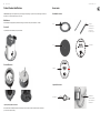
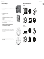
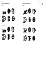
Product Feature Identi cation
IMPORTANT NOTE: Drawings for each loudspeaker below are generic and apply to the loudspeaker types specified. Some variations will be apparent in some models,
but differences are not critical for installation purposes except as noted.
Blind Mount
The blind-mount models are supplied with a pre-fitted backcan. Above applies to all models as well any others that do NOT have a “PI” suffix.
Pre-install
A pre-install (PI) unit is shown without the optional pre-install backcan.
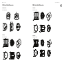
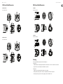
Pre-install backcan
Optional pre-install (PI) backcan for PI models.
NOTE: The CMS 603DC/ICT and CMS 803DC models have the transformer pre-attached to the inside of the backcan. The CMS 503DC/ICT has the transformer
pre-attached to the loudspeaker assembly.
Accessories
Standard Accessories
Optional Accessories
C-Ring
Grille
Paint Mask
Cut-out template
Tile-bridge kit
Note: A tile-bridge kit
must always be used
when installing into
suspended ceiling tiles
60 W Transformer
Note: For use with CMS
803 PI in distributed lines
without backcans.
Plaster (mud) ring

10 CMS 3.0 Series Quick Start Guide 11
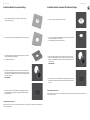
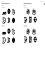
Installation Guide for Suspended Ceilings
1. Remove the ceiling tile from its frame and place it on a at surface. Position the cutout template
(self adhesive backed) on the tile. (Fig.1)
2. Cut out the hole in the ceiling tile using a pad saw following the broken line indicated on the template (Fig.2)
3. Place the C-Ring and tile-bridge on top of the ceiling panel, aligning the C-Ring over the hole, and screw the
C-Ring to the tile bridge using the xings provided. (Fig.3)
4. Go to the ‘Wiring and Setting Up’ chapter.
5. Slide the speaker assembly through the hole. Turn the screws (denoted “Screw Fix”) clockwise on the front
of the speaker to extend the mounting wings. Tighten the screws until a rm grip is achieved. (NOTE: Screws
have a PoziDriv head; use of a PoziDriv driver is recommended). If using a power driver,
TANNOY
recommends a
torque setting of 1.5 Nm. (Fig.4)
DO NOT OVERTIGHTEN!
6. Attach the nylon safety to the hooks on the front ba e before attaching the grille by presenting it to the
speakers and allowing the magnets to pull it into position (Fig.5). (With the CMS 403DCe/ICTe, the grille is
already tted to the product.)
NOTE ON INSTALLATION OF CMS 403DCe/ICTe:
Before tightening the screws in step 5, swivel the speaker in the desired direction. When the screws are tightened, the speaker will lock into position. Replace the front
trim to conceal the mounting screws.
Fig.1
Fig.2
Fig.3
Fig.4
Fig.5
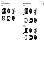
Installation Guide for Sheetrock (Plasterboard) Ceilings
1. Position the cutout template (self adhesive backed) on the ceiling. (Fig.1)
2. Cut out the hole in the ceiling using a pad saw following the broken line indicated on the template then slide the
C-Ring into the ceiling, aligning it over the cut-out hole. (Fig.2)
3. Go to the ‘Wiring and Setting Up’ chapter, then return to point 4 below.
4. Slide the speaker assembly through the hole. Turn the screws (denoted “Screw Fix”) clockwise on the front of
the speaker to extend the mounting wings. Tighten the screws until a rm grip is achieved. (NOTE: Screws have
a PoziDriv head; use of a PoziDriv driver is recommended). If using a power driver,
TANNOY
recommends a torque
setting of 1.5 Nm. (Fig.3)
DO NOT OVERTIGHTEN!
5. Attach the nylon safety to the hooks on the front ba e before attaching the grille by presenting it to the speakers
and allowing the magnets to pull it into position (Fig.4). (With the CMS 403DCe/ICTe, the grille is already tted to
the product.)
NOTE ON INSTALLATION OF CMS 403DCe/ICTe:
Before tightening the screws in step 4, swivel the speaker in the desired direction. When the screws are tightened, the speaker will lock into position. Replace the front
trim to conceal the mounting screws.
Fig.1
Fig.2
Fig.3
Fig.4

12 CMS 3.0 Series Quick Start Guide 13
Installation Guide for Optional Plaster Ring
An optional plaster (mud) ring bracket is available from TANNOY. This bracket is designed to be pre-installed into newly constructed, non-suspended ceilings.
1. Nail or screw the plaster ring to the joists. (Fig.1)
2. Lay the speaker wiring to where the speaker will be tted and complete the plastering work on the ceiling. (Fig.2)
3. Go to the ‘Wiring and Setting Up’ chapter, then return to point 4 below.
4. Slide the speaker assembly through the hole. Turn the screws (denoted “Screw Fix”) clockwise on the front of
the speaker to extend the mounting wings. Tighten the screws until a rm grip is achieved. (Note: Screws have a
PoziDriv head; use of a PoziDriv driver is recommended). If using a power driver,
TANNOY
recommends a torque
setting of 1.5 Nm. (Fig.3)
DO NOT OVERTIGHTEN!
5. Attach the nylon safety to the hooks on the front ba e before attaching the grille by presenting it to the speakers
and allowing the magnets to pull it into position (Fig.4). (With the CMS 403DCe/ICTe, the grille is already tted to
the product.)
NOTE ON INSTALLATION OF CMS 403DCe/ICTe:
Before tightening the screws in step 4, swivel the speaker in the desired direction. When the screws are tightened, the speaker will lock into position. Replace the front
trim to conceal the mounting screws.
Fig.1
Fig.2
Fig.3
Fig.4
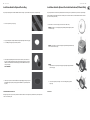
Installation Guide for Optional Pre-Installation Backcan (PI Models Only)
An optional pre-install backcan is available for all pre-install (PI) models. The backcan is designed for pre-installation in newly constructed, non-suspended ceilings.
NOTE: The CMS 603DC/ICT and CMS 803DC models have the transformer pre-attached to the inside of the backcan; the CMS 503DC/ICT models have the transformer
pre-attached to the loudspeaker assembly.
1. Attach the backcan to a safe and secure xing point. This can be done in a number of ways:
METHOD 1: Fix the backcan to a secure fixing point by using suitable fixings with the 4 fixing holes provided
on the PI backcan. (Fig.1)
METHOD 2: Secure the backcan to a safe and secure fixing point using suitable fixings with the flexible straps
that are attached to the PI backcan. (Fig.2)
METHOD 3:
a. Attach the PI backcan to the optional pre-mount ring (plaster ring) using the fixings provided with the
pre-mount ring. (Fig.3)
b. Next, secure the wings of the pre-mount ring to a safe and secure fixing point by using suitable
fixings. (Fig.4)
Please turn over
Fig.1
Fig.2
Fig.3
Fig.4

14 CMS 3.0 Series Quick Start Guide 15
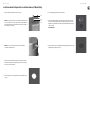
Installation Guide for Optional Pre-Installation Backcan (PI Models Only)
2. Attach the conduit to the installed backcan. This can be done in two ways:
METHOD 1: You can use the clamp at the back of the pre-install backcan. The product will accept a
squeeze connector with a thread size of up to 22 mm: To remove the cable clamp, simply unscrew
the threaded washer (under the wiring cover) which holds the cable clamp in place and replace it
with a conduit squeeze connector. (Fig.5)
METHOD 2: You can use any of the three knock-out points at the sides of the PI backcan
(19 mm, 22 mm or 28 mm diameter). (Fig.6)
3. If conduit is not chosen as the wiring method, run an approved speaker cable to the installed can.
Terminate in the top mounted cable clamp or with an approved cable connector in one of the three
knock-out points at the sides of the PI backcan.
4. Cut hole in the proper location in the ceiling using a pad saw. Place the pre-install backcan over the
hole. (Fig.7)
Conduit
Conduit
Squeeze
Connector
Fig.5
Fig.6
Fig.7
5. Go to the ‘Wiring and Setting Up’ chapter, then return to point 6 below.
6. Slide the speaker assembly through the hole. Turn the screws (denoted “Screw Fix”) clockwise on the front of
the speaker to extend the mounting wings. Tighten the screws until a rm grip is achieved. (NOTE: Screws have
a PoziDriv head; use of a PoziDriv driver is recommended). If using a power driver,
TANNOY
recommends a torque
setting of 1.5 Nm. (Fig.8)
DO NOT OVERTIGHTEN!
7. Attach the nylon safety to the hooks on the front ba e before attaching the grille by presenting it to the speakers
and allowing the magnets to pull it into position. (Fig.9)
Fig.8
Fig.9

16 CMS 3.0 Series Quick Start Guide 17
Wiring and Setting Up
1. Open the wiring cover (if applicable) and locate the Euro-type connector plug and socket at the back
of the speaker. (Fig.1)
2. For connection to an ampli er, use Pins 1 and 2 (Fig.2):
• Pin 1 is positive
• Pin 2 is negative
For connection to additional speakers in a distributed line, Pins 3 and 4 are in parallel where:
• Pin 3 is negative
• Pin 4 is positive
3. Close the wiring cover and tighten both screws on the cable clamp (if applicable).
4. Use the rotary switch on the front of the unit to select low impedance (LoZ) mode or high impedance
(70 V or 100 V) for distributed applications.
THE SPEAKER IS SUPPLIED IN LOW IMPEDANCE MODE. NEVER CONNECT THE SPEAKER TO
A 70/100 VOLT AMPLIFIER WHILE IT IS SET FOR LOW IMPEDANCE.
CMS 403DCe/ICTe and CMS 503DC/ICT models (all variants) use a 30 W transformer. In distributed line
applications, the transformer can be tapped at 30 W, 15 W and 7.5 W, with an additional 3.75 W tap
for 70 V line systems. (Fig.3)
CMS 603DC/ICT and CMS 803DC models (all variants) use a 60 W transformer. In distributed line
applications, the transformer can be tapped at 60 W, 30 W and 15 W, with an additional 7.5 W tap for
70 V line systems. (Fig.4)
Fig.1
Fig.2
Fig.3
Fig.4
CMS Series Model Dimensions
CMS 803DC BM
Hole Cut-out Size: 295 mm
CMS 803DC PI
Hole Cut-out Size: 295 mm
319.0
[12.56"]
327.7
[12.90"]
5.2
[0.20"]
310.5
[12.22"]
286.4
[11.27"]
319.0
[12.56"]
286.4
[11.27"]
125.6
[4.94"]
5.2
[0.20"]

18 CMS 3.0 Series Quick Start Guide 19
CMS Series Model Dimensions
CMS 803DC PI BACKCAN
Hole Cut-out Size: 295 mm
CMS 803DCQ
Hole Cut-out Size: 295 mm
Ø397.0
[15.63"]
Ø291.4
[11.47"]
Ø365.0
[14.37"]
8.8
[0.35"]
151.2
[5.95"]
168.5
[6.63"]
319.0
[12.56"]
327.7
[12.90"]
5.2
[0.20"]
310.5
[12.22"]
286.4
[11.27"]
CMS Series Model Dimensions
CMS 603DC BM
Hole Cut-out Size: 253 mm
CMS 603ICT BM
Hole Cut-out Size: 253 mm
273.3
[10.76"]
4.2
[0.17"]
255.8
[10.07"]
244.3
[9.62"]
274.0
[10.79"]
273.8
[10.78"]
4.1
[0.16"]
256.5
[10.10"]
244.3
[9.62"]
274.0
[10.79"]

20 CMS 3.0 Series Quick Start Guide 21
CMS Series Model Dimensions
CMS 603DC PI
Hole Cut-out Size: 253 mm
CMS 603ICT PI
Hole Cut-out Size: 253 mm
274.0
[10.79"]
4.1
[0.16"]
244.3
[9.62"]
100.0
[3.94"]
100.0
[3.94"]
4.1
[0.16"]
244.3
[9.62"]
273.5
[10.77"]
CMS Series Model Dimensions
CMS 603DC PI BACKCAN
Hole Cut-out Size: 253 mm
CMS 603ICT PI BACKCAN
Hole Cut-out Size: 253 mm
Ø351.0
[13.82"]
Ø249.4
[9.82"]
168.5
[6.63"]
8.8
[0.35"]
151.2
[5.95"]
Ø319.0
[12.56"]
Ø351.0
[13.82"]
Ø249.4
[9.82"]
168.5
[6.63"]
8.8
[0.35"]
151.2
[5.95"]
Ø319.0
[12.56"]

22 CMS 3.0 Series Quick Start Guide 23
CMS Series Model Dimensions
CMS 603ICT LS
Hole Cut-out Size: 253 mm
273.8
[10.78"]
4.1
[0.16"]
256.5
[10.10"]
244.3
[9.62"]
274.0
[10.79"]
CMS Series Model Dimensions
CMS 503DC BM
Hole Cut-out Size: 190 mm
CMS 503ICT BM
Hole Cut-out Size: 190 mm
205.9
[8.11"]
181.3
[7.14"]
205.3
[8.08"]
188.0
[7.40"]
4.5
[0.18"]
205.9
[8.11"]
181.3
[7.14"]
205.8
[8.10"]
188.5
[7.42"]
4.2
[0.17"]

24 CMS 3.0 Series Quick Start Guide 25
CMS Series Model Dimensions
CMS 503DC LP
Hole Cut-out Size: 253 mm
CMS 503ICT LP
Hole Cut-out Size: 253 mm
274.0
[10.79"]
98.6
[3.88"]
4.2
[0.17"]
244.3
[9.62"]
274.0
[10.79"]
98.6
[3.88"]
4.2
[0.17"]
244.3
[9.62"]
CMS Series Model Dimensions
CMS 503DC PI
Hole Cut-out Size: 190 mm
CMS 503ICT PI
Hole Cut-out Size: 190 mm
205.9
[8.11"]
133.3
[5.25"]
4.2
[0.17"]
205.9
[8.11"]
131.7
[5.19"]
4.2
[0.17"]
181.3
[7.14"]

26 CMS 3.0 Series Quick Start Guide 27
CMS Series Model Dimensions
CMS 503DC PI BACKCAN
Hole Cut-out Size: 190 mm
CMS 503ICT PI BACKCAN
Hole Cut-out Size: 190 mm
Ø288.0
[11.34"]
Ø256.0
[10.08"]
8.8
[0.35"]
136.2
[5.36"]
153.5
[6.04"]
Ø186.4
[7.34"]
Ø288.0
[11.34"]
Ø256.0
[10.08"]
8.8
[0.35"]
136.2
[5.36"]
153.5
[6.04"]
Ø186.4
[7.34"]
CMS Series Model Dimensions
CMS 403DCe
Hole Cut-out Size: 187 mm
CMS 403ICTe
Hole Cut-out Size: 187 mm
Painting
If desired, the grille and baffle panel may be painted to match the surrounding décor.
Painting the baffle:
• Carefully mask o the driver assembly using the paint mask provided to ensure that the paint does not come into contact with the cone and roll surround.
• Apply several thin coats of paint – this will provide a better nish than one overly thick coat.
Painting the grille:
• Carefully remove the acoustically transparent grille cloth from the reverse side of the grille.
• Paint the grille and then replace the grille cloth - several thin coats of paint will provide a better nish than one overly thick coat.
• Re-bond the grille cloth to the grille over the entire area using a light spray-adhesive to avoid audible resonances.
Ø205.0
[8.07"]
34.2
[1.35"]
147.6
[5.81"]
Ø181.1
[7.13"]
Ø205.0
34.2
[1.35"]
147.6
[5.81"]
Ø181.1
[7.13"]

28 CMS 3.0 Series Quick Start Guide 29
Technical Speci cations
CMS 803DC Models CMS 803DCQ Model
Performance
Frequency response (-3 dB)
(1)
47 Hz - 30 kHz BM Backcan 47 Hz - 30 kHz
Frequency range (-10 dB)
(1)
40 Hz - 35 kHz BM Backcan
Frequency range (-10 dB)
(1)
41 Hz - 35 kHz PI Backcan
System sensitivity (1 W @ 1 m)
(2)
92 dB (1 W = 4 V for 16 Ohms) 93 dB (1 W = 4 V for 16 Ohms)
Nominal Coverage Angle 90 degrees conical 60 degrees conical
Power Handling
(3)
Average 90 W
Programme 180 W
Peak 360 W
Recommended Amplifier Power 180 W @ 16 Ohms
Nominal Impedance (Lo, Z) 16 Ohms
Rated maximum SPL
Average 112 dB 113 dB
Peak 118 dB 119 dB
With THP60 - Average 110 dB 111 dB
Transformer Taps (via front rotary switch)
70 V 60 W (83 Ω) / 30 W (165 Ω) / 15 W (330 Ω) / 7.5 W (660 Ω) / OFF & low impedance operation
100 V 60 W (165 Ω) / 30 W (330 Ω) / 15 W (660 Ω) / OFF & low impedance operation
Transducers
Dual Concentric point source driver 1 x 200 mm (8.0") Dual Concentric driver, using Omnimagnet technology
Low Frequency 44 mm (1.75") voice coil, treated multi ber paper pulp cone
High Frequency 25 mm (1.00") PEI dome
Physical
Enclosure
Backcan Zinc plated steel
Ba e Re ex loaded UL 94V-0 rated ABS
Grille Steel, with weather resistant coating
Safety Features Safety ring located at rear of enclosure for load bearing safety bond
Clamping Design Security toggle clamp Min / Max clamping range 9.5 mm (0.37") / 60 mm (2.36") Recommended clamp torque: 1.5 Nm
Backcan Options
Blind Mount (BM) Complete with xed backcan —
Pre Install (PI) Separate backcan for pre-installation —
Cable Entry Options Cable clamp & squeeze connector for conduit up to 22 mm
Conduit Knockouts on PI Backcan 3 Sets of horizontal positions 19 / 22 / 28 mm (0.75" / 0.87" / 1.10")
Connectors Removable locking connector with screw terminals with “loop through” facility
Compliance UL-1480, UL-2043, CE
Notes:
1. Average over stated bandwidth. Measured in an IEC ba e in an Anechoic Chamber
2. Unweighted pink noise input, measured at 1 metre on axis
3. Long term power handling capacity as de ned in EIA - 426B test
A full range of measurements, performance data, CLF and Ease Data for CMS 803DC/CMS 803DCQ can be downloaded from www.tannoypro.com.
TANNOY operates a policy of continuous research and development. The introduction of new materials or manufacturing methods may introduce variations in actual performance; however, actual performance always will equal or exceed the published speci cations, which
TANNOY reserves the right to alter without prior notice. Please verify the latest speci cations when dealing with critical applications.
CMS 803DC Models CMS 803DCQ Model
Physical
Dimensions
Bezel diameter 319.0 mm (12.56")
Front of ceiling to rear of backcan — 310.5 mm (12.22")
Front of ceiling to top of safety loop — 327.7 mm (12.90")
BM Model: Front of ceiling to rear of backcan 310.5 mm (12.22") —
BM Model: Front of ceiling to top of safety loop 327.7 mm (12.90") —
PI Model: Front of ceiling surface to rear of speaker unit 125.6 mm (4.94") —
PI Model: Front of accessory backcan bezel to top of
safety loop
168.5 mm (6.63") —
Hole cutout diameter (all models) 295 mm (11.61")
Net Weight (ea) — 8.5 kg (18.74 lbs)
CMS 803DC BM 8.5 kg (18.74 lbs) —
CMS 803DC PI 5.0 kg (11.02 lbs) —
PI Backcan 4.2 kg (9.25 lbs) —
Included Accessories C-Ring, tile-bridge kit, paint mask, cut-out template, grille
Optional Accessories Plaster (mud) ring, Arco grille
Packed Quantity 2

30 CMS 3.0 Series Quick Start Guide 31
CMS 603DC Models CMS 603ICT Models
Performance
Frequency response (-3 dB)
(1)
BM Backcan 75 Hz - 30 kHz 78 Hz - 22 kHz
Frequency range (-10 dB)
(1)
BM Backcan 50 Hz - 30 kHz 51 Hz - 24 kHz
Frequency range (-10 dB)
(1)
PI Backcan 46 Hz - 30 kHz 46 Hz - 24 kHz
System sensitivity (1 W @ 1 m)
(2)
91 dB (1 W = 4 V for 16 Ohms)
Nominal Coverage Angle 90 degrees conical 90 degrees conical
Coverage Angle (1 kHz to 6 kHz) 92 degrees
Directivity Factor (Q) 7.1 averaged 1 kHz to 6 kHz
Directivity Index (DI) 7.9 averaged 1 kHz to 6 kHz
Power Handling
(3)
Average 80 W 60 W
Programme 160 W 120 W
Peak 320 W 240 W
Recommended Amplifier Power 160 W @ 16 Ohms 120 W @ 16 Ohms
Nominal Impedance (Lo, Z) 16 Ohms
Rated maximum SPL
Average 110 dB 109 dB
Peak 116 dB 115 dB
Transformer Taps (via front rotary switch)
70 V 60 W (83 Ω) / 30 W (165 Ω) / 15 W (330 Ω) / 7.5 W (660 Ω) / OFF & low impedance operation
100 V 60 W (165 Ω) / 30 W (330 Ω) / 15 W (660 Ω) / OFF & low impedance operation
Crossover — 7 kHz inductively coupled
Transducers
Dual Concentric point source driver
1 x 165 mm (6.5") Dual Concentric driver,
using Omnimagnet technology
—
Low Frequency 44 mm (1.75") voice coil, treated multi ber paper pulp cone 165 mm (6.50") mineral loaded polypropylene
High Frequency 25 mm (1.00") PEI dome ICT aluminium dome
Physical
Enclosure
Backcan Zinc plated steel
Ba e Re ex loaded UL 94V-0 rated ABS
Grille Steel, with weather resistant coating
Safety Features Safety ring located at rear of enclosure for load bearing safety bond
CMS 603ICT LS UL 1480 UUMW certi cation for Life Safety applications
Clamping Design Security toggle clamp Min / Max clamping range 9.5 mm (0.37") / 60 mm (2.36") Recommended clamp torque: 1.5 Nm
Backcan Options
Blind Mount (BM) Complete with xed backcan
Pre Install (PI) Separate backcan for pre-installation
Cable Entry Options Cable clamp & squeeze connector for conduit up to 22 mm
Conduit Knockouts on PI Backcan 3 Sets of horizontal positions 19 / 22 / 28 mm (0.75" / 0.87" / 1.10")
Connectors Removable locking connector with screw terminals with “loop through” facility
Compliance UL-1480, UL-2043, CE
Notes:
1. Average over stated bandwidth. Measured in an IEC ba e in an Anechoic Chamber
2. Unweighted pink noise input, measured at 1 metre on axis
3. Long term power handling capacity as de ned in EIA - 426B test
A full range of measurements, performance data, CLF and Ease Data for CMS 603DC/CMS 603ICT can be downloaded from www.tannoypro.com.
TANNOY operates a policy of continuous research and development. The introduction of new materials or manufacturing methods may introduce variations in actual performance; however, actual performance always will equal or exceed the published speci cations, which
TANNOY reserves the right to alter without prior notice. Please verify the latest speci cations when dealing with critical applications.
CMS 603DC Models CMS 603ICT Models
Physical
Dimensions
Bezel diameter 274.0 mm (10.79")
BM Model: Front of ceiling to rear of backcan 255.8 mm (10.07") 256.5 mm (10.10")
BM Model: Front of ceiling to top of safety loop 273.3 mm (10.76") 273.8 mm (10.78")
PI Model: Front of ceiling surface to rear of speaker unit 100.7 mm (3.96") 100.0 mm (3.94")
PI Model: Front of accessory backcan bezel to top of
safety loop
168.5 mm (6.60")
Hole cutout diameter (all models) 253 mm (9.96")
Net Weight (ea)
CMS 603DC BM 6.6 kg (14.6 lbs) —
CMS 603DC PI 3.8 kg (8.37 lbs) —
CMS 603ICT BM — 5.4 kg (11.9 lbs)
CMS 603ICT PI — 2.7 kg (5.95 lbs)
PI Backcan 3.7 kg (8.1 lbs)
Included Accessories C-Ring, tile-bridge kit, paint mask, cut-out template, grille
Optional Accessories Plaster (mud) ring, Arco grille
Packed Quantity 2

32 CMS 3.0 Series Quick Start Guide 33
CMS 503DC Models CMS 503DC LP Model
Performance
Frequency response (-3 dB)
(1)
85 Hz - 50 kHz BM Backcan 88 Hz - 22 kHz
Frequency range (-10 dB)
(1)
74 Hz - 54 kHz BM Backcan 77 Hz - 24 kHz
Frequency range (-10 dB)
(1)
70 Hz - 54 kHz PI Backcan —
System sensitivity (1 W @ 1 m)
(2)
89 dB (1 W = 4 V for 16 Ohms)
Nominal Coverage Angle 90 degrees conical
Power Handling
(3)
Average 60 W
Programme 120 W
Peak 240 W
Recommended Amplifier Power 120 W @ 16 Ohms
Nominal Impedance (Lo, Z) 16 Ohms
Rated maximum SPL
Average 107 dB
Peak 113 dB
Transformer Taps (via front rotary switch)
70 V 30 W (165 Ω) / 15 W (330 Ω) / 7.5 W (660 Ω) / 3.75 W (1320 Ω) / OFF & low impedance operation
100 V 30 W (330 Ω) / 15 W (660 Ω) / 7.5 W (1320 Ω) / OFF & low impedance operation
Transducers
Dual Concentric point source driver 1 x 130 mm (5.0") Dual Concentric driver, using Omnimagnet technology
Low Frequency 35 mm (1.38") voice coil, treated multi ber paper pulp cone
High Frequency 20 mm (0.79") PEI dome
Physical
Enclosure
Backcan Zinc plated steel
Ba e Re ex loaded UL 94V-0 rated ABS
Grille Steel, with weather resistant coating
Safety Features Safety ring located at rear of enclosure for load bearing safety bond
Clamping Design Security toggle clamp Min / Max clamping range 9.5 mm (0.37") / 60 mm (2.36") Recommended clamp torque: 1.5 Nm
Backcan Options
Blind Mount (BM) Complete with xed backcan —
Pre Install (PI) Separate backcan for pre-installation —
Cable Entry Options Cable clamp & squeeze connector for conduit up to 22 mm
Conduit Knockouts on PI Backcan
3 Sets of horizontal positions 19 / 22 / 28 mm
(0.75" / 0.87" / 1.10")
—
Connectors Removable locking connector with screw terminals with “loop through” facility
Compliance UL-1480, UL-2043, CE
Dimensions
Bezel diameter 205.9 mm (8.11") 274.0 mm (10.79")
Front of ceiling to rear of backcan — 98.6 mm (3.88")
BM Model: Front of ceiling to rear of backcan 188.0 mm (7.40") —
BM Model: Front of ceiling to top of safety loop 205.3 mm (8.08") —
PI Model: Front of ceiling surface to rear of speaker unit 133.3 mm (5.25") —
PI Model: Front of accessory backcan bezel to top of
safety loop
153.5 mm (6.04") —
Hole cutout diameter (all models) 190 mm (7.48") 253.0 mm (9.96")
Net Weight (ea) — 4.7 kg (10.36 lbs)
CMS 503DC BM 4.3 kg (9.47 lbs) —
CMS 503DC PI 3.2 kg (7.05 lbs) —
PI Backcan 1.9 kg (4.18 lbs) —
Included Accessories C-Ring, tile-bridge kit, paint mask, cut-out template, grille
Optional Accessories Plaster (mud) ring, Arco grille
Packed Quantity 2
Notes:
1. Average over stated bandwidth. Measured in an IEC ba e in an Anechoic Chamber
2. Unweighted pink noise input, measured at 1 metre on axis
3. Long term power handling capacity as de ned in EIA - 426B test
A full range of measurements, performance data, CLF and Ease Data for CMS 503DC/CMS 503DC LP can be downloaded from www.tannoypro.com.
TANNOY operates a policy of continuous research and development. The introduction of new materials or manufacturing methods may introduce variations in actual performance; however, actual performance always will equal or exceed the published speci cations, which
TANNOY reserves the right to alter without prior notice. Please verify the latest speci cations when dealing with critical applications.
CMS 503ICT Models CMS 503ICT LP Model
Performance
Frequency response (-3 dB)
(1)
85 Hz - 22 kHz BM Backcan 88 Hz - 50 kHz
Frequency range (-10 dB)
(1)
74 Hz - 24 kHz BM Backcan 77 Hz - 54 kHz
Frequency range (-10 dB)
(1)
71 Hz - 24 kHz PI Backcan —
System sensitivity (1 W @ 1 m)
(2)
89 dB (1 W = 4 V for 16 Ohms)
Nominal Coverage Angle 90 degrees conical
Coverage Angle (1 kHz to 6 kHz) 105 degrees —
Directivity Factor (Q) 5.6 averaged 1 kHz to 6 kHz —
Directivity Index (DI) 7.0 averaged 1 kHz to 6 kHz —
Power Handling
(3)
Average 50 W
Programme 100 W
Peak 200 W
Recommended Amplifier Power 100 W @ 16 Ohms
Nominal Impedance (Lo, Z) 16 Ohms
Rated maximum SPL
Average 106 dB
Peak 112 dB
Transformer Taps (via front rotary switch)
70 V 30 W (165 Ω) / 15 W (330 Ω) / 7.5 W (660 Ω) / 3.75 W (1320 Ω) / OFF & low impedance operation
100 V 30 W (330 Ω) / 15 W (660 Ω) / 7.5 W (1320 Ω) / OFF & low impedance operation
Crossover 7 kHz inductively coupled —
Transducers
Low Frequency 130 mm (5.00") mineral loaded polypropylene 1 x 130 mm (5.0") mineral loaded polypropylene
High Frequency ICT aluminium dome ICT
Physical
Enclosure
Backcan Zinc plated steel
Ba e Re ex loaded UL 94V-0 rated ABS
Grille Steel, with weather resistant coating
Safety Features Safety ring located at rear of enclosure for load bearing safety bond
Clamping Design
Security toggle clamp Min / Max clamping range 9.5 mm (0.37") / 60 mm (2.36") Recommended clamp torque: 1.5 Nm
Backcan Options
Blind Mount (BM) Complete with xed backcan —
Pre Install (PI) Separate backcan for pre-installation —
Cable Entry Options Cable clamp & squeeze connector for conduit up to 22 mm
Conduit Knockouts on PI Backcan
3 Sets of horizontal positions 19 / 22 / 28 mm
(0.75" / 0.87" / 1.10")
—
Connectors Removable locking connector with screw terminals with “loop through” facility
Compliance UL-1480, UL-2043, CE
Dimensions
Bezel diameter 205.9 mm (8.11") 274.0 mm (10.79")
Front of ceiling to rear of backcan 98.6 mm (3.88")
BM Model: Front of ceiling to rear of backcan 188.5 mm (7.42") 98.6 mm (3.88")
BM Model: Front of ceiling to top of safety loop 205.8 mm (8.10") —
PI Model: Front of ceiling surface to rear of speaker unit 131.7 mm (5.19") —
PI Model: Front of accessory backcan bezel to top of
safety loop
153.5 mm (6.04")
Hole cutout diameter (all models) 190 mm (7.48") 253.0 mm (9.96")
Net Weight (ea) — 4.4 kg (9.70 lbs)
CMS 503ICT BM 3.95 kg (8.70 lbs) —
CMS 503ICT PI 2.95 kg (6.50 lbs) —
PI Backcan 1.9 kg (4.18 lbs) —
Included Accessories C-Ring, tile-bridge kit, paint mask, cut-out template, grille
Optional Accessories Plaster (mud) ring, Arco grille
Packed Quantity 2
Notes:
1. Average over stated bandwidth. Measured in an IEC ba e in an Anechoic Chamber
2. Unweighted pink noise input, measured at 1 metre on axis
3. Long term power handling capacity as de ned in EIA - 426B test
A full range of measurements, performance data, CLF and Ease Data for CMS 503ICT/CMS 503ICT LP can be downloaded from www.tannoypro.com.
TANNOY operates a policy of continuous research and development. The introduction of new materials or manufacturing methods may introduce variations in actual performance; however, actual performance always will equal or exceed the published speci cations, which
TANNOY reserves the right to alter without prior notice. Please verify the latest speci cations when dealing with critical applications.

34 CMS 3.0 Series Quick Start Guide 35
Other important information
1. Register online. Please register your new
Music Tribe equipment right after you purchase it by
visiting tannoy.com. Registering your purchase using our
simple online form helps us to process your repair claims
more quickly and e ciently. Also, read the terms and
conditions of our warranty, if applicable.
2. Malfunction. Should your Music Tribe
Authorized Reseller not be located in your vicinity,
you may contact the Music Tribe Authorized Ful ller for
your country listed under “Support” at tannoy.com. Should
your country not be listed, please check if your problem
can be dealt with by our “Online Support” which may also
be found under “Support” at tannoy.com. Alternatively,
please submit an online warranty claim at behringer.com
BEFORE returning the product.
3. Power Connections. Before plugging the
unit into a power socket, please make sure you are using
the correct mains voltage for your particular model.
Faulty fuses must be replaced with fuses of the same type
and rating without exception.
Important information
CMS 403DCe Model CMS 403ICTe Model
Performance
Frequency response (-3 dB)
(1)
110 Hz - 50 kHz BM Backcan 110 Hz - 22 kHz
Frequency range (-10 dB)
(1)
80 Hz - 54 kHz BM Backcan 80 Hz - 24 kHz
System sensitivity (1 W @ 1 m)
(2)
88 dB (1 W = 4 V for 16 Ohms)
Nominal Coverage Angle 90 degrees conical
Coverage Angle (1 kHz to 6 kHz) —120 degrees
Directivity Factor (Q) — 5.26 averaged 1 kHz to 6 kHz
Directivity Index (DI) — 6.30 averaged 1 kHz to 6 kHz
Power Handling
(3)
Average 40 W
Peak 160 W
Recommended Amplifier Power 80 W @ 16 Ohms
Nominal Impedance (Lo, Z) 16 Ohms
Rated maximum SPL
Average 104 dB
Peak 110 dB
Transformer Taps (via front rotary switch)
70 V 30 W (165 Ω) / 15 W (330 Ω) / 7.5 W (660 Ω) / 3.75 W (1320 Ω) / OFF & low impedance operation
100 V 30 W (330 Ω) / 15 W (660 Ω) / 7.5 W (1320 Ω) / OFF & low impedance operation
Crossover — 7 kHz inductively coupled
Transducers
Dual Concentric point source driver
1 x 100 mm (4.0") Dual Concentric driver,
using Omnimagnet technology
100 mm (4.00") mineral loaded polypropylene
Low Frequency 35 mm (1.38") voice coil, treated multi ber paper pulp cone 19 mm (0.75") ICT aluminium dome
High Frequency 20 mm (0.79") PEI dome —
Physical
Enclosure
Backcan Re ex loaded UL 94V-0 rated ABS
Ba e Re ex loaded UL 94V-0 rated ABS
Grille Steel, with weather resistant coating
Safety Features Safety ring located at rear of enclosure for load bearing safety bond
Clamping Design Min / Max clamping range: 0.0 mm (0.0") / 20.0 mm (0.79")Recommended clamp torque: 1.5 Nm
Backcan
Blind Mount (BM) Complete with xed backcan —
Connectors Removable locking connector with screw terminals with “loop through” facility
Compliance UL-1480, UL-2043, CE
Dimensions
Bezel diameter 205.0 mm (8.07")
Front of ceiling to rear of pod 147.6 mm (5.81")
Hole cutout diameter 187 mm (7.36")
Net Weight (ea) 3.2 kg (7.05 lbs) 3.0 kg (6.61 lbs)
Included Accessories C-Ring, tile-bridge kit, paint mask, cut-out template, grille
Optional Accessories Plaster (mud) ring
Packed Quantity 2
Notes:
1. Average over stated bandwidth. Measured in an IEC ba e in an Anechoic Chamber
2. Unweighted pink noise input, measured at 1 metre on axis
3. Long term power handling capacity as de ned in EIA - 426B test A full range of measurements, performance data, CLF and Ease Data for CMS 403DCe/CMS 403ICTe can be downloaded from www.tannoypro.com.
TANNOY operates a policy of continuous research and development. The introduction of new materials or manufacturing methods may introduce variations in actual performance; however, actual performance always will equal or exceed the published speci cations, which
TANNOY reserves the right to alter without prior notice. Please verify the latest speci cations when dealing with critical applications.

-
 1
1
-
 2
2
-
 3
3
-
 4
4
-
 5
5
-
 6
6
-
 7
7
-
 8
8
-
 9
9
-
 10
10
-
 11
11
-
 12
12
-
 13
13
-
 14
14
-
 15
15
-
 16
16
-
 17
17
-
 18
18
-
 19
19


Tannoy CMS 503ICT LP Schnellstartanleitung
- Kategorie
- Autolautsprecher
- Typ
- Schnellstartanleitung
in anderen Sprachen
- English: Tannoy CMS 503ICT LP Quick start guide
- français: Tannoy CMS 503ICT LP Guide de démarrage rapide
- português: Tannoy CMS 503ICT LP Guia rápido
Verwandte Artikel
-
Tannoy CMS 803 PI 16 OHM BACKCAN Schnellstartanleitung
-
Tannoy iW 6DS-WH Schnellstartanleitung
-
-
-
Tannoy BACK CAN PCI 7DC RB Schnellstartanleitung
-
Tannoy AMS 5ICT Benutzerhandbuch
-
-
Tannoy CMS 503DC BM Schnellstartanleitung
-
Tannoy QCI A1-BL Schnellstartanleitung
-
Tannoy CMS 603DC BM Schnellstartanleitung