
D Umgebungstemperatur von maximal 65°C (UL), 70° (IEC)
F Température ambiante maximale de 65°C (UL), 70° (IEC)
EN
Surrounding air temperature rating of 65°C (UL), 70° (IEC)
D
Gewährleistung
Sichere Funktion ist dann gewährleistet, wenn die in
dieser Installationsanleitung beschriebenen Mon-
tage arbeiten korrekt ausgeführt worden sind und die
Funktionskontrolle vor und während des Betriebs ge-
mäss Beschreibung in dieser Installationsanleitung
durchgeführt wird. Ausserdem sind die Hinweise in
der Bedienungsanleitung zu beachten.
Sicherheit
An den Geräten dürfen keine Reparaturen oder Modi-
fikationen vorgenommen werden.
Autorisierte Personen
Montage-, Anschluss- und Demontagearbeiten dür-
fen ausschliesslich von elektrotechnisch unterwiese-
nen Personen ausgeführt werden.
Entsorgung
Defekte Geräte sind als Sondermüll an entsprechend
eingerichteten Sammelstellen zu entsorgen. Natio-
nale oder regionale Vorschriften über die Entsorgung
von Sondermüll sind zu befolgen.
F
Garantie
Le fonctionnement est garanti seulement si le mon-
tage décrit dans les instructions d’installation a été
correctement réalisé et un contrôle de fonctionne-
ment effectué avant et pendant l’utilisation, confor-
mément à la description donnée ci-dessous. Par
conséquent, il est impératif de respecter les instruc-
tions d’utilisation et d’installation.
Sécurité
Il est interdit d’effectuer des réparations ou des mo-
difications sur les appareils.
Personnes autorisées
Les travaux de montage, de raccordement et de dé-
montage doivent être effectués exclusivement par
du personnel qualifié en électricité.
Recyclage
Les appareils défectueux doivent être recyclés
comme des déchets spéciaux aux points de collecte
prévus à cet effet. Il est impératif de respecter les
règles nationales ou régionales en matière de recy-
clage des déchets spéciaux.
EN
Guarantee
The safe operation is assured if the assembly work
has been carried out according to these user instruc-
tions. Furthermore, the instructions in the manual
must be observed.
Safety
Any repair or modification measures to the devices
are not permitted.
Authorised persons
Assembly, connection and removal work should only
be carried out by authorized and qualified persons.
Disposal
Faulty products should be treated as hazardous
waste and disposed of in an appropriate manner.
National or regional regulations regarding the dis-
posal of hazardous waste should be adhered to.
2CCC481010M1001
Open-core sensor
2CCC481009M1001
Solid-core sensor
2CCC481014M0201
CMS-660 user manual
CMS-660 USB drivers for Windows
—
INSTALLATION MANUAL
Control Unit CMS-660
Unité de contrôle CMS-660

CMS
BUS
DIGITAL
INPUT
Status
Network
Reset
USB
2
4
1
3
2 CONTROL UNIT CMS-660 I UNITÉ DE CONTRÔLE CMS-660 INSTALLATION MANUAL
Document number 2CCC481013M0601 Rev. A (09.2018)
—
© Copyright 2018 ABB. All rights reserved.
Due to possible changes in design and
materials, the features and sizes cont-
ained in this catalog are to be considered
as binding only after confirmation by ABB.
—
ABB Switzerland Ltd.
Low Voltage Products
Fulachstrasse 150
CH-8201 Schaffhausen
Telefon: +41 58 586 41 11
Telefax: +49 58 586 42 22
www.abb.com/lowvoltage
D
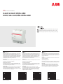
Produktübersicht
Fig. 1
Komponente Beschreibung
1 CMS-Bus-Schnittstelle
2 Digitaleingang
3 Anschlussklemmen für 24 V DC Versorgung
4 Anschlussklemmen für RS-485 (2-adrig)
Montage auf 35 mm DIN-Schiene / Demontage
Fig. 2a / Fig. 2b
Anschlussschema
Fig. 3
F
Vue d‘ensemble du produit
Fig. 1
Composants Description
1 Interface CMS-bus
2 Port d'entrée numérique
3 Alimentation externe 24 V CC
4 Port série RS-485 : Modbus RTU
Montage sur rail DIN 35 mm / Démontage
Fig. 2a / Fig. 2b
Schéma de raccordement
Fig. 3
EN
Product overview
Fig. 1
Part Description
1 CMS-Bus interface
2 Digital input port
3 24 V DC external power supply
4 Serial RS-485 port: Modbus RTU
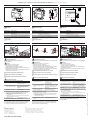
Assembly on 35 mm DIN rail / Dismantling
Fig. 2a / Fig. 2b
Connection diagram
Fig. 3
Fig. 1
CMS
BUS
DIGITAL
INPUT
Status
Network
Reset
USB
1
2
4
3
Fig. 3Fig. 2a Fig. 2b
Fig. 4
Fig. 6
Fig. 5
D
Montage CMS-Sensoren
Siehe Installationsanleitung 2CCC481010M1001 oder
2CCC481009M1001.
Hinweis
• Steckverbinder nur einmal verwenden
• Maximal 32 Sensoren anschliessen
• Maximale Länge des Flachbandkabels beachten
• Flachbandkabel darf keine Zugkräfte auf Sensoren ausüben, sonst
sind Messabweichungen möglich
• Luftdistanz von min. 5,5 mm vom Flachbandkabel zu blanken span-
nungsführenden Teilen einhalten
Platzierung der Steckverbinder mit Stift markieren
Fig. 4
Montieren der Steckverbinder mit Parallelzange
Fig. 5
Steckverbinder an Control Unit und Sensoren anschliessen
Fig. 6
Inbetriebnahme CMS-660
Manuelle Erstinbetriebnahme Beschreibung
1 CMS-660 an externes
Netzteil anschliessen
Das Gerät schaltet sich ein
und die Erstinbetriebnahme
startet automatisch.
2 Status-LED am CMS-660
beginnt gelb zu blinken
Dies zeigt an, dass kein Sensor
angelernt ist; gleichzeitig
blinkt die LED jedes Sensors
langsam.
3 Druckknopf am Sensor
drücken
Die LED des Sensors leuchtet
nun dauerhaft.
4 Sobald alle Sensoren hinzugefügt sind, gibt es drei
Möglichkeiten den Inbetriebnahmemodus zu verlassen
(a) Automatisch nach einer definierten Zeit
(b) Durch Drücken der Reset-Taste für < 1 Sekunde
(1 Signalton)
(c) Durch dreimaliges Drücken der Drucktaste des zuletzt
konfigurierten CMS-Sensors
5 Alle Sensoren sind
adressiert: Normalbetrieb
Status-LED am CMS-660
leuchtet grün.
Gerne weitere Informationen der Bedienungsanleitung
2CCC481014M0201 entnehmen, falls nach der ersten Inbetriebnahme
des Gerätes der Konfigurationsmodus erneut aufgerufen werden
muss, z.B. wenn ein weiterer Sensor adressiert werden muss
.
F
Montage des capteurs CMS
Voir la notice d‘installation 2CCC481010M1001 ou 2CCC481009M1001.
Avertissement
• N‘utiliser les connecteurs qu‘une seule fois
• Raccorder au maximum 32 capteurs
• Respectez la longueur maximale du câble plat
• Le bus de communication CMS ne doit exercer aucune pression sur
les capteurs, sinon des écarts de mesure sont possibles
• Une distance minimale de 5,5 mm entre le câble plat et des pièces
sous tension non isolées doit être respectée
Marquer l‘emplacement des connecteurs avec un crayon
Fig. 4
Montage des connecteurs avec une pince parallèle
Fig. 5
Raccordement des connecteurs à l‘unité de contrôle et aux capteurs
Fig. 6
Mise en service du système CMS-660
Mise en service initiale Details
1 Brancher le CMS-660 sur
l’alimentation externe
L’appareil s’allume et le
processus de première mise en
service se lance
automatiquement.
2 La LED status du CMS-660
commence à clignoter en
jaune
Indique qu’aucun capteur n’est
affecté ; parallèlement, la LED
de chaque capteur clignote
lentement.
3 Appuyer sur le bouton-
poussoir du capteur
La LED du capteur s’allume
maintenant en continu.
4 Une fois tous les capteurs ajoutés, il y a trois façons de
quitter le mode mise en service
(a) Délai de configuration expiré
(b) Appuyer sur le bouton Reset (Réinitialisation) pendant
< 1 seconde (1 bip)
(c) Appuyer trois fois sur le bouton-poussoir du dernier
capteur CMS configuré
5 Tous les capteurs sont
affectés : fonctionnement
normal
La LED status de l’unité de
contrôle passe au vert.
Si vous devez repasser en mode configuration après la première
mise en service de l‘appareil, (p. ex. un capteur supplémentaire
doit être affecté à l‘unité de contrôle), veuillez vous reporter au
manuel d‘utilisation 2CCC481014M0201.
EN
Mounting of CMS sensors
Refer to instruction manual 2CCC481010M1001 or 2CCC481009M1001.
Warning
• Use connectors only once
• Connect a max. number of 32 sensors
Consider the maximum flat cable length
• Flat cable should not exert force to the sensor, other wise measur-
ing deviations are possible
• Keep a distance of min. 5.5 mm from the flat cable to uninsulated
live parts
Mark desired placement of connectors with a pen
Fig. 4
Press connector set with a parallel pliers together
Fig. 5
Plug connectors to Control Unit and sensors
Fig. 6
System commissioning CMS-660
Manual initial commissioning Details
1 Connect CMS-660 to
external power supply
Device switches on and initial
commissioning automatically
starts.
2 Status LED on CMS-660
starts to blink yellow
Indicates no sensor assigned;
at the same time, the LED of
each sensor is flashing slowly.
3 Press push button on the
sensor
The sensor’s LED now lights up
continuously.
4 Once all sensor are added, there are three ways to leave the
commissioning mode
(a) Configured timeout
(b) Push the reset button for < 1 sec (1 beep)
(c) Click the push button of the last configured CMS sensor
for three times
5 All sensors are assigned:
normal operation
Status LED on control unit
changes to green.
If it is necessary to enter the configuration mode again after the first
commissioning of the device (e.g. one more sensor has to be assigned
to the control unit), please refer to the user manual
2CCC481014M0201.
CMS
BUS
DIGITAL
INPUT
CMS-660
Control Unit
USB
Status
Network
Reset
RS 485 24 V DC
A B + –
6 mm
0.24 in
∅ max. 0.5 mm
2
1 x AWG 26-20
8 mm
0.31 in
∅ max. 2.5 mm
2
1 x AWG 20-13
0.5 – 0.6 Nm
4.4 – 5.3 lb-in
Push-in spring
connection
CMS
BUS
DIGITAL
INPUT
✔
CMS
BUS
DIGITAL
INPUT
-
 1
1
-
 2
2


in anderen Sprachen
- English: ABB CMS-660 Installation guide
- français: ABB CMS-660 Guide d'installation
Verwandte Artikel
Andere Dokumente
-
DeLOCK 86469 Datenblatt
-
AVENTICS Bus Control CMS, B-Design, EtherNet/IP? Bedienungsanleitung
-
Tannoy CMS 503DC BM Schnellstartanleitung
-
Tannoy CMS 503ICT LP Schnellstartanleitung
-
Tannoy CMS 603DC BM Schnellstartanleitung
-
DYNACORD CMS1000 Benutzerhandbuch
-
-
-
Hitachi VTMX900EUK Benutzerhandbuch