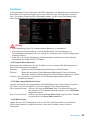
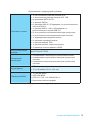
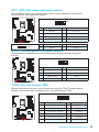
MSI MS-7984v1.0 Bedienungsanleitung
- Kategorie
- Motherboards
- Typ
- Bedienungsanleitung
Dieses Handbuch eignet sich auch für

I
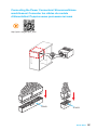
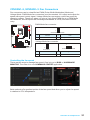
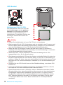
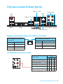
Quick Start
Quick Start
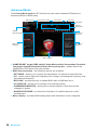
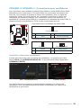
Thank you for purchasing the MSI
®
Z170A GAMING PRO
motherboard. This Quick Start section provides demonstration
diagrams about how to install your computer. Some of the
installations also provide video demonstrations. Please link to the
URL to watch it with the web browser on your phone or tablet. You
may have even link to the URL by scanning the QR code.
Kurzanleitung
Danke, dass Sie das MSI
®
Z170A GAMING PRO Motherboard
gewählt haben. Dieser Abschnitt der Kurzanleitung bietet eine Demo
zur Installation Ihres Computers. Manche Installationen bieten
auch die Videodemonstrationen. Klicken Sie auf die URL, um diese
Videoanleitung mit Ihrem Browser auf Ihrem Handy oder Table
anzusehen. Oder scannen Sie auch den QR Code mit Ihrem Handy,
um die URL zu öffnen.
Présentation rapide
Merci d’avoir choisi la carte mère MSI
®
Z170A GAMING PRO.
Ce manuel fournit une rapide présentation avec des illustrations
explicatives qui vous aideront à assembler votre ordinateur. Des
tutoriels vidéo sont disponibles pour certaines étapes. Cliquez sur
le lien fourni pour regarder la vidéo sur votre téléphone ou votre
tablette. Vous pouvez également accéder au lien en scannant le QR
code qui lui est associé.
Быстрый старт
Благодарим вас за покупку материнской платы MSI
®
Z170A
GAMING PRO. В этом разделе представлена информация,
которая поможет вам при сборке комьютера. Для некоторых
этапов сборки имеются видеоинструкции. Для просмотра видео,
необходимо открыть соответствующую ссылку в веб-браузере
на вашем телефоне или планшете. Вы также можете выполнить
переход по ссылке, путем сканирования QR-кода.

II
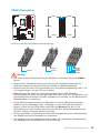
Quick Start
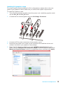
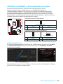
http://youtu.be/bf5La099urI
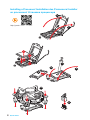
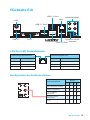
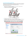
Installing a Processor/ Installation des Prozessors/ Installer
un processeur/ Установка процессора
1
2
3
6
4
5
7
8
9

III
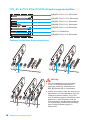
Quick Start
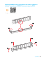
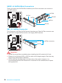
1
1
2
2
3
3
Installing DDR4 memory/ Installation des DDR4-Speichers/
Installer une mémoire DDR4/ Установка памяти DDR4
http://youtu.be/T03aDrJPyQs

IV
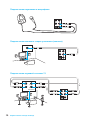
Quick Start
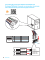
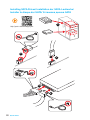
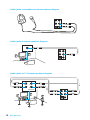
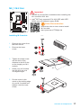
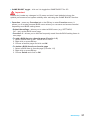
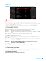
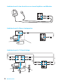
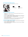
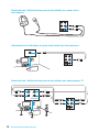
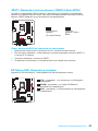
Connecting the Front Panel Header/ Anschließen der
Frontpanel-Stiftleiste/ Connecter un connecteur du panneau
avant/ Подключение разъемов передней панели
http://youtu.be/DPELIdVNZUI
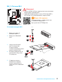
1
2 10
9
JFP1
1 HDD LED + 2 Power LED +
3 HDD LED - 4 Power LED -
5 Reset Switch 6 Power Switch
7 Reset Switch 8 Power Switch
9 Reserved 10 No Pin
RESET SW
POWER SW
POWER LED+
POWER LED-
HDD LED
HDD LED
RESET SW
JFP1
HDD LED
HDD LED -
HDD LED +
POWER LED -
POWER LED +
POWER LED

V
Quick Start
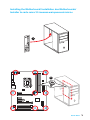
Installing the Motherboard/ Installation des Motherboards/
Installer la carte mère/ Установка материнской платы
1
2

VI
Quick Start
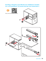
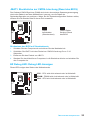
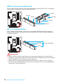
Installing SATA Drives/ Installation der SATA-Laufwerke/
Installer le disque dur SATA/ Установка дисков SATA
http://youtu.be/RZsMpqxythc
1
2
3
4
5

VII
Quick Start
1
4
5
Installing a Graphics Card/ Einbau der Grafikkarte/ Installer
une carte graphique/ Установка дискретной видеокарты
http://youtu.be/mG0GZpr9w_A
2
3

VIII
Quick Start
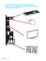
Connecting Peripheral Devices/ Peripheriegeräte/
Connecter un périphérique anschliessen/ Подключение
периферийных устройств

IX
Quick Start
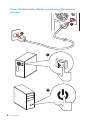
Connecting the Power Connectors/ Stromanschlüsse
anschliessen/ Connecter les câbles du module
d’alimentation/ Подключение разъемов питания
http://youtu.be/gkDYyR_83I4
JPWR1
JPWR2

X
Quick Start
Power On/ Einschalten/ Mettre sous-tension/ Включение
питания
1
4
2
3

1
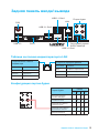
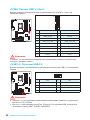
Contents
Contents
Safety Information ...................................................................................................2
Specifications ..........................................................................................................3
Rear I/O Panel ..........................................................................................................9
LAN Port LED Status Table ................................................................................. 9
Audio Ports Configuration .................................................................................... 9
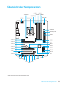
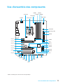
Overview of Components ....................................................................................11
CPU Socket ....................................................................................................... 12
DIMM Slots ........................................................................................................ 13
PCI_E1~6, PCI1: PCIe/ PCI Expansion Slots.................................................... 14
SATA1~6: SATA 6Gb/s Connectors .................................................................. 16
SE1_21: SATAe Connector ............................................................................... 16
M2_1: M.2 Slot ................................................................................................... 17
JPWR1~2: Power Connectors ........................................................................... 18
JFP1, JFP2: Front Panel Connectors ................................................................ 19
JAUD1: Front Audio Connector ......................................................................... 19
JTPM1: TPM Module Connector ....................................................................... 19
JUSB3: USB 3.1 Gen1 Connector ..................................................................... 20
JUSB1~2: USB 2.0 Connectors......................................................................... 20
CPUFAN1~2, SYSFAN1~3: Fan Connectors .................................................... 21
JCI1: Chassis Intrusion Connector .................................................................... 22
JBAT1: Clear CMOS (Reset BIOS) Jumper ...................................................... 23
EZ Debug LED: Debug LED indicators ............................................................ 23
BIOS Setup .............................................................................................................24
Entering BIOS Setup ......................................................................................... 24
Resetting BIOS .................................................................................................. 25
Updating BIOS ................................................................................................... 25
EZ Mode ............................................................................................................ 26
Advanced Mode ................................................................................................ 28
OC Menu ........................................................................................................... 29
Software Description ............................................................................................36
Installing Windows
®
7/ 8.1/ 10 ........................................................................... 36
Installing Drivers ................................................................................................ 36
Installing Utilities ................................................................................................ 36

2
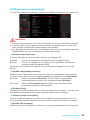
Safety Information
Safety Information
● The components included in this package are prone to damage from electrostatic
discharge (ESD). Please adhere to the following instructions to ensure successful
computer assembly.
● Ensure that all components are securely connected. Loose connections may cause
the computer to not recognize a component or fail to start.
● Hold the motherboard by the edges to avoid touching sensitive components.
● It is recommended to wear an electrostatic discharge (ESD) wrist strap when
handling the motherboard to prevent electrostatic damage. If an ESD wrist strap is
not available, discharge yourself of static electricity by touching another metal object
before handling the motherboard.
● Store the motherboard in an electrostatic shielding container or on an anti-static pad
whenever the motherboard is not installed.
● Before turning on the computer, ensure that there are no loose screws or metal
components on the motherboard or anywhere within the computer case.
● Do not boot the computer before installation is completed. This could cause
permanent damage to the components as well as injury to the user.
● If you need help during any installation step, please consult a certified computer
technician.
● Always turn off the power supply and unplug the power cord from the power outlet
before installing or removing any computer component.
● Keep this user guide for future reference.
● Keep this motherboard away from humidity.
● Make sure that your electrical outlet provides the same voltage as is indicated on
the PSU, before connecting the PSU to the electrical outlet.
● Place the power cord such a way that people can not step on it. Do not place
anything over the power cord.
● All cautions and warnings on the motherboard should be noted.
● If any of the following situations arises, get the motherboard checked by service
personnel:
▶ Liquid has penetrated into the computer.
▶ The motherboard has been exposed to moisture.
▶ The motherboard does not work well or you can not get it work according to user
guide.
▶ The motherboard has been dropped and damaged.
▶ The motherboard has obvious sign of breakage.
● Do not leave this motherboard in an environment above 60°C (140°F), it may
damage the motherboard.

3
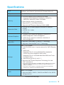
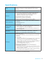
Specications
Specifications
CPU
Supports 6th Gen Intel
®
Core
™
i3/i5/i7 processors, and Intel
®
Pentium
®
and Celeron
®
processors for Socket LGA1151
Chipset Intel
®
Z170 Chipset
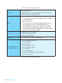
Memory
● 4x DDR4 memory slots, support up to 64GB
▶ Supports DDR4 3600(OC)/ 3200(OC)/ 3000(OC)/
2800(OC)/ 2600(OC)/ 2400/ 2133 MHz
● Dual channel memory architecture
● Supports ECC, un-buffered memory
● Supports Intel
®
Extreme Memory Profile (XMP)
Expansion Slots
● 3x PCIe 3.0 x16 slots (support x16/x0/x4 or x8/x8/x4
modes)
● 3x PCIe 3.0 x1 slots
● 1x PCI slot
Onboard Graphics
● 1x HDMI
™
port, support a maximum resolution of
4096x2160@24Hz, 2560x1600@60Hz
● 1x DVI-D port, support a maximum resolution of
1920x1200@60Hz
Multi-GPU
● Supports 3-Way AMD
®
CrossFire™ Technology
● Supports 2-Way NVIDIA
®
SLI™ Technology
Storage
Intel
®
Z170 Chipset
● 6x SATA 6Gb/s ports* (2 ports reserved for SATA Express
port)
● 1x M.2 slot*
▶ Supports PCIe 3.0 x4 and SATA 6Gb/s standards,
4.2cm/ 6cm/ 8cm length M.2 SSD cards
▶ Supports PCIe 3.0 x4 NVMe Mini-SAS SSD with Turbo
U.2 Host Card**
● 1x SATAe port (PCIe 3.0 x2)*/ ***
● Supports Intel
®
Smart Response Technology for Intel
Core
™
processors
* SATA5 and SATA6 ports will be unavailable when installing the M.2 module
in M.2 slot. SATA and SATAe ports maximum support 6x SATAs or 1x
SATAe + 4x SATAs.
** The Turbo U.2 Host Card is not included, please purchase separately.
*** SATAe port is backward compatible with SATA.
RAID
Intel
®
Z170 Chipset
● Supports RAID 0, RAID 1, RAID 5 and RAID 10 for SATA
storage devices
Continued on next page

4
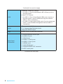
Specications
Continued from previous page
USB
● ASMedia
®
ASM1142 Chipset
▶ 2x USB 3.1 Gen2 (SuperSpeed USB 10Gbps) ports on
the back panel
● Intel
®
Z170 Chipset
▶ 6x USB 3.1 Gen1 (SuperSpeed USB) ports (4 ports on
the back panel, 2 ports available through the internal
USB 3.1 Gen1 connector)
▶ 6x USB 2.0 (High-speed USB) ports (2 ports on the back
panel, 4 ports available through the internal USB 2.0
connectors)
Audio
● Realtek
®
ALC1150 Codec
● 7.1-Channel High Definition Audio
● Supports S/PDIF output
LAN 1x Intel
®
I219-V Gigabit LAN controller
Back Panel
Connectors
● 1x PS/2 keyboard/ mouse port
● 2x USB 2.0 ports
● 1x DVI-D port
● 2x USB 3.1 Gen2 ports
● 4x USB 3.1 Gen1 ports
● 1x HDMI
™
port
● 1x LAN (RJ45) port
● 1x Optical S/PDIF OUT connector
● 5x OFC audio jacks
Continued on next page

5
Specications
Continued from previous page
Internal Connectors
● 1x 24-pin ATX main power connector
● 1x 8-pin ATX 12V power connector
● 6x SATA 6Gb/s connectors
● 1x SATAe connector
● 2x USB 2.0 connectors (supports additional 4 USB 2.0
ports)
● 1x USB 3.1 Gen1 connector (supports additional 2 USB
3.1 Gen1 ports)
● 2x 4-pin CPU fan connectors
● 3x 4-pin system fan connectors
● 1x Front panel audio connector
● 2x Front panel connectors
● 1x TPM module connector
● 1x Chassis Intrusion connector
● 1x Clear CMOS jumper
I/O Controller NUVOTON NCT6793 Controller Chip
Hardware Monitor
● CPU/System temperature detection
● CPU/System fan speed detection
● CPU/System fan speed control
Form Factor
● ATX Form Factor
● 12 in. x 9.6 in. (30.5 cm x 24.4 cm)
BIOS Features
● 1x 128 Mb flash
● UEFI AMI BIOS
● ACPI 5.0, PnP 1.0a, SM BIOS 2.8
● Multi-language
Continued on next page

6
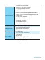
Specications
Continued from previous page
Software
● Drivers
● COMMAND CENTER
● LIVE UPDATE 6
● FAST BOOT
● SUPER CHARGER
● GAMING APP
● M-CLOUD
● RAMDISK
● GAMING LAN MANAGER
● Open Broadcaster Software
● Intel
®
Extreme Tuning Utility
● Norton
™
Security
● Google Chrome
™
,Google Toolbar, Google Drive
● SteelSeries Engine 3
● CPU-Z
Continued on next page

7
Specications
Continued from previous page
Performance
GAMING Features
● MYSTIC LIGHT
▶ 16.5 Million Colors
▶ 8 LED Effects
● AUDIO BOOST 3
▶ Isolated Audio PCB
▶ EMI Shielding
▶ Dual Headphone Amplifiers
▶ High Quality Audio Capacitors
▶ Golden Audio Connectors
● GAME BOOST
▶ Easy Overclocking
● GAMING LAN
▶ Intel I219-V Gigabit Ethernet
▶ MSI Network Manager
▶ Electric Wave Surge
● GAMING APP
▶ System Mode Switching: OC/Gaming/Silent
▶ Gaming Hotkey
▶ Gaming Mouse Master
▶ Gaming LED Control
● GAMING CERTIFIED
● Open Broadcaster Software
▶ Encoding using H264 (x264) and AAC.
▶ Support for Intel Quick Sync Video (QSV) and NVENC.
▶ Unlimited number of scenes and sources.
▶ Live RTMP streaming to Twitch, YouTube, DailyMotion,
Hitbox and more.
Continued on next page

8
Specications
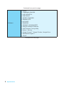
Continued from previous page
MSI Exclusive
Features
● CLICK BIOS 5
▶ EZ Mode & Advanced Mode Switching
▶ Board Explorer
▶ Hardware Monitor
● MILITARY CLASS 5
▶ Military Class Component
▶ Military Class Stability and Reliability
- ESD Protection
- EMI Protection
- Humidity Protection
- Circuit Protection
- High Temperature Protection
- Steel Armor PCIe Slots
● COMMAND CENTER
▶ System Monitor
▶ Smart Fan Control
● RAMDISK
● LIVE UPDATE 6
● M-CLOUD
● CPU-Z
● EZ Debug LED
Specification
Highlights
● DDR4 Boost Support
▶ Dual-Channel DDR4 Memory Support
▶ Isolated DDR4 Circuit Design
▶ DDR4 XMP Ready
● PCI Express 3.0 Support
▶ 2-Way Nvidia SLI
TM
Support
▶ 3-Way AMD CrossFire
TM
Support
● USB 3.1 Gen2 Ready
▶ USB 3.1 Gen2 (10 Gb/s) Type-A Ready
● Turbo M.2 Ready
▶ PCIe 3.0 x4 (32 Gb/s) Support
▶ PCIe / SATA Dual Mode Support
● SATA Express Support
● NVMe / AHCI Driver Support
● U.2 Support (Optional)

9
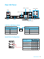
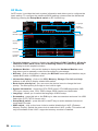
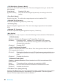
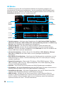
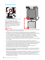
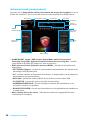
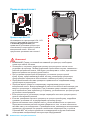
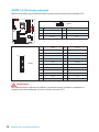
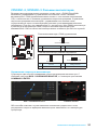
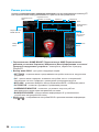
Rear I/O Panel
Rear I/O Panel
PS/2
LAN
USB 3.1 Gen1
USB 3.1 Gen2
Audio Ports
USB 2.0
USB 3.1 Gen1
Optical S/PDIF-Out
Link/ Activity LED
Status Description
Off No link
Yellow Linked
Blinking Data activity
Speed LED
Status Description
Off 10 Mbps connection
Green 100 Mbps connection
Orange 1 Gbps connection
LAN Port LED Status Table
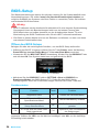
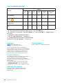
Audio Ports Configuration
Audio Ports
Channel
2 4 6 8
Center/ Subwoofer Out ● ●
Rear Speaker Out ● ● ●
Line-In/ Side Speaker Out ●
Line-Out/ Front Speaker Out ● ● ● ●
Mic In
(●: connected, Blank: empty)
DVI-D

10
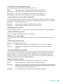
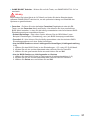
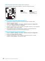
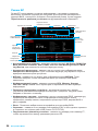
Rear I/O Panel
AUDIO INPUT
Rear Front
Side Center/
Subwoofer
Audio jacks to headphone and microphone diagram
Audio jacks to stereo speakers diagram
Audio jacks to 7.1-channel speakers diagram
AUDIO INPUT
Seite wird geladen ...
Seite wird geladen ...
Seite wird geladen ...
Seite wird geladen ...
Seite wird geladen ...
Seite wird geladen ...
Seite wird geladen ...
Seite wird geladen ...
Seite wird geladen ...
Seite wird geladen ...
Seite wird geladen ...
Seite wird geladen ...
Seite wird geladen ...
Seite wird geladen ...
Seite wird geladen ...
Seite wird geladen ...
Seite wird geladen ...
Seite wird geladen ...
Seite wird geladen ...
Seite wird geladen ...
Seite wird geladen ...
Seite wird geladen ...
Seite wird geladen ...
Seite wird geladen ...
Seite wird geladen ...
Seite wird geladen ...
Seite wird geladen ...
Seite wird geladen ...
Seite wird geladen ...
Seite wird geladen ...
Seite wird geladen ...
Seite wird geladen ...
Seite wird geladen ...
Seite wird geladen ...
Seite wird geladen ...
Seite wird geladen ...
Seite wird geladen ...
Seite wird geladen ...
Seite wird geladen ...
Seite wird geladen ...
Seite wird geladen ...
Seite wird geladen ...
Seite wird geladen ...
Seite wird geladen ...
Seite wird geladen ...
Seite wird geladen ...
Seite wird geladen ...
Seite wird geladen ...
Seite wird geladen ...
Seite wird geladen ...
Seite wird geladen ...
Seite wird geladen ...
Seite wird geladen ...
Seite wird geladen ...
Seite wird geladen ...
Seite wird geladen ...
Seite wird geladen ...
Seite wird geladen ...
Seite wird geladen ...
Seite wird geladen ...
Seite wird geladen ...
Seite wird geladen ...
Seite wird geladen ...
Seite wird geladen ...
Seite wird geladen ...
Seite wird geladen ...
Seite wird geladen ...
Seite wird geladen ...
Seite wird geladen ...
Seite wird geladen ...
Seite wird geladen ...
Seite wird geladen ...
Seite wird geladen ...
Seite wird geladen ...
Seite wird geladen ...
Seite wird geladen ...
Seite wird geladen ...
Seite wird geladen ...
Seite wird geladen ...
Seite wird geladen ...
Seite wird geladen ...
Seite wird geladen ...
Seite wird geladen ...
Seite wird geladen ...
Seite wird geladen ...
Seite wird geladen ...
Seite wird geladen ...
Seite wird geladen ...
Seite wird geladen ...
Seite wird geladen ...
Seite wird geladen ...
Seite wird geladen ...
Seite wird geladen ...
Seite wird geladen ...
Seite wird geladen ...
Seite wird geladen ...
Seite wird geladen ...
Seite wird geladen ...
Seite wird geladen ...
Seite wird geladen ...
Seite wird geladen ...
Seite wird geladen ...
Seite wird geladen ...
Seite wird geladen ...
Seite wird geladen ...
Seite wird geladen ...
Seite wird geladen ...
Seite wird geladen ...
Seite wird geladen ...
Seite wird geladen ...
Seite wird geladen ...
Seite wird geladen ...
Seite wird geladen ...
Seite wird geladen ...
Seite wird geladen ...
Seite wird geladen ...
Seite wird geladen ...
Seite wird geladen ...
Seite wird geladen ...
Seite wird geladen ...
Seite wird geladen ...
Seite wird geladen ...
Seite wird geladen ...
Seite wird geladen ...
Seite wird geladen ...
Seite wird geladen ...
Seite wird geladen ...
Seite wird geladen ...
Seite wird geladen ...
Seite wird geladen ...
Seite wird geladen ...
Seite wird geladen ...
Seite wird geladen ...
Seite wird geladen ...
Seite wird geladen ...
Seite wird geladen ...
Seite wird geladen ...
Seite wird geladen ...
Seite wird geladen ...
Seite wird geladen ...
Seite wird geladen ...
Seite wird geladen ...
-
 1
1
-
 2
2
-
 3
3
-
 4
4
-
 5
5
-
 6
6
-
 7
7
-
 8
8
-
 9
9
-
 10
10
-
 11
11
-
 12
12
-
 13
13
-
 14
14
-
 15
15
-
 16
16
-
 17
17
-
 18
18
-
 19
19
-
 20
20
-
 21
21
-
 22
22
-
 23
23
-
 24
24
-
 25
25
-
 26
26
-
 27
27
-
 28
28
-
 29
29
-
 30
30
-
 31
31
-
 32
32
-
 33
33
-
 34
34
-
 35
35
-
 36
36
-
 37
37
-
 38
38
-
 39
39
-
 40
40
-
 41
41
-
 42
42
-
 43
43
-
 44
44
-
 45
45
-
 46
46
-
 47
47
-
 48
48
-
 49
49
-
 50
50
-
 51
51
-
 52
52
-
 53
53
-
 54
54
-
 55
55
-
 56
56
-
 57
57
-
 58
58
-
 59
59
-
 60
60
-
 61
61
-
 62
62
-
 63
63
-
 64
64
-
 65
65
-
 66
66
-
 67
67
-
 68
68
-
 69
69
-
 70
70
-
 71
71
-
 72
72
-
 73
73
-
 74
74
-
 75
75
-
 76
76
-
 77
77
-
 78
78
-
 79
79
-
 80
80
-
 81
81
-
 82
82
-
 83
83
-
 84
84
-
 85
85
-
 86
86
-
 87
87
-
 88
88
-
 89
89
-
 90
90
-
 91
91
-
 92
92
-
 93
93
-
 94
94
-
 95
95
-
 96
96
-
 97
97
-
 98
98
-
 99
99
-
 100
100
-
 101
101
-
 102
102
-
 103
103
-
 104
104
-
 105
105
-
 106
106
-
 107
107
-
 108
108
-
 109
109
-
 110
110
-
 111
111
-
 112
112
-
 113
113
-
 114
114
-
 115
115
-
 116
116
-
 117
117
-
 118
118
-
 119
119
-
 120
120
-
 121
121
-
 122
122
-
 123
123
-
 124
124
-
 125
125
-
 126
126
-
 127
127
-
 128
128
-
 129
129
-
 130
130
-
 131
131
-
 132
132
-
 133
133
-
 134
134
-
 135
135
-
 136
136
-
 137
137
-
 138
138
-
 139
139
-
 140
140
-
 141
141
-
 142
142
-
 143
143
-
 144
144
-
 145
145
-
 146
146
-
 147
147
-
 148
148
-
 149
149
-
 150
150
-
 151
151
-
 152
152
-
 153
153
-
 154
154
-
 155
155
-
 156
156
-
 157
157
-
 158
158
-
 159
159
-
 160
160
-
 161
161
-
 162
162


MSI MS-7984v1.0 Bedienungsanleitung
- Kategorie
- Motherboards
- Typ
- Bedienungsanleitung
- Dieses Handbuch eignet sich auch für
in anderen Sprachen
Verwandte Artikel
-
MSI Z170A SLI PLUS Bedienungsanleitung
-
MSI Z170A-G45 GAMING Bedienungsanleitung
-
-
-
-
-
MSI MS-7A12 v1.1 Bedienungsanleitung
-
-
-
MSI Z170A GAMING M9 ACK Bedienungsanleitung