
1
Betriebsanleitung
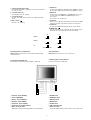
Farb-Monitor VMC-10/2 und VMC-14/2
Operating Instructions
Colour Monitor VMC-10/2 and VMC-14/2
Notice d’emploi
Moniteur couleur VMC-10/2 et VMC-14/2
Instrucciones de manejo
Monitor color VMC-10/2 y VMC-14/2

2
Contents
General Descriptions
Safety instructions
1 Installation
1.1 General notes for installation
1.2 Single connection
1.3 Monitor multiple connection
2 Starting / Operation
2.1 Monitor setting / controls VMC-10/2
2.2 Monitor setting / controls VMC-14/2
2.3 Rear side connectors
3 Maintenance
3.1 Cleaning
3.2 Services
4 Specifications
4.1 Technical data
General descriptions
• Possible use as a closed circuit television monitor or a video preview/
playback monitor.
• NTSC - / PAL auto-selection system.
• Rugged metal cabinet.
• The monitor could be stacked.
• Video A/B, Y/C input selector control. Audio input/output capabilitiy.
• Video A/B input/output looping with automatic 75 Ω termination,
Y/C input/output looping with impedance selector for high impedance
or 75 Ω termination.
• Volume control, contrast control, bright control, colour control,
sharpness control (VMC-14/2 only) tint control ,Video A/B selector,
Y/C selector and power control are on the front side of the monitor.
• Connectors for power supply, Video A/B input/output looping, Audio
A/B and Y/C impedance switch are on the rear side of the monitor.
• Loudspeaker is integrated.
• Detachable power cord.
• Universal power input.
Safety instructions
• The following instructions are for your own safety and should be
observed without failure.
• Please read these safety and operating instructions before putting the
unit into operation.
• Keep the operating instructions in a safe place for later use.
• The monitor emits only a small amount of heat during operation.
Nevertheless, heat has to be dissipated and sufficient fresh air has to
be supplied.
• Circulation of air has to be guaranteed, therefore do not cover the
ventilating slots.
• Enough distance to other appliances or walls is necessary.
Accumulation of heat reduces the service life of the monitor and might
set it on fire in the worst case.
Inhalt
Allgemeine Beschreibung
Sicherheitshinweise
1 Installation
1.1 Allgemeine Hinweise zur Aufstellung
1.2 Einzelanschluss des Monitors
1.3 Anschluss mehrerer Monitore
2 Inbetriebnahme / Bedienung
2.1 Monitoreinstellung VMC-10/2
2.2 Monitoreinstellung VMC-14/2
2.3 Monitoranschlüsse auf der Rückseite
3 Wartung
3.1 Pflege
3.2 Hinweise auf Reparaturdienste
4 Spezifikationen
4.1 Technische Daten
Allgemeine Beschreibung
• Das Gerät kann als Vorschaumonitor und zur Wiedergabe aufgezeich-
neter Bilder eingesetzt werden.
• Automatische Umschaltung von PAL- auf NTSC- Betrieb.
• Robustes Metallgehäuse.
• Der Monitor ist stapelbar.
• Der Monitor verfügt über zwei Video (FBAS) - Durchschleifeingänge A
und B sowie einen Y/C - und einen Audio-Durchschleifeingang.
• Der Y/C - Videoanschluss ist mit einem zuschaltbaren 75 Ω -
Abschlusswiderstand versehen, der bei Einzelbetrieb, oder wenn der
Monitor als letztes Gerät im Durchschleifbetrieb benutzt wird, zuge-
schaltet sein muss (Schalter auf „75 Ω”). Bei den beiden FBAS -
Eingängen wird der 75 Ω - Abschluss, abhängig von der Betriebsart:
Einzel- oder Durchschleifbetrieb, automatisch geschaltet.
• An der Frontseite befinden sich Lautstärke-, Kontrast-, Helligkeits-,
Farbkontrast- und Tint-Regler, sowie Video A/B, Y/C-Wahltasten mit
LED-Kontrollanzeige und die Netztaste.
• An der Rückseite sind der Netzeingang, der Y/C-Signalabschluss-
Schalter und die Ein-/ Ausgänge von Video A/B und Audio A/B.
• Im Gerät ist ein Lautsprecher integriert.
• Steckbares Netzanschlusskabel.
• Universal-Netzeingang.
Sicherheitshinweise
• Bevor Sie das Gerät anschließen und in Betrieb nehmen, lesen Sie
bitte zuerst die Sicherheitshinweise und die Betriebsanleitung.
• Bewahren Sie die Betriebsanleitung für spätere Verwendung sorgfältig
auf.
• Der Monitor gibt bei Betrieb nur wenig Wärme ab, trotzdem muss die
Wärme abgeführt und ausreichend Frischluft zugeführt werden.
• Lüftungsschlitze des Gerätes niemals abdecken, da die Luftzirkulation
gewährleistet sein muss.
• Auf ausreichenden Abstand zu anderen Geräten oder zur Wand
achten, da Wärmestaus zur Überhitzung führen, die die Lebensdauer
verringert und im Extremfall den Monitor in Brand setzen kann.
• Bei Betrieb in geschlossenen Regalwänden sind unbedingt ausrei-
chende Abstände einzuhalten.

3
• If put into operation in built-in shelves, it is absolutely necessary to
leave enough space for ventilation.
• If the monitor is brought from a cold environment into warm rooms, it
is necessary to wait until the monitor has adapted room temperature
and until any condensation water, which might be on the picture tube
has evaporated, before connecting and switching on the monitor.
• To prevent fire or shock hazard, do not expose this appliance to rain,
water or wet locations. Should any liquid or solid object fall into the
cabinet, unplug the unit and have it checked by the qualified personnel
before operating it any further.
• Use the monitor under conditions where temperature is within 0°C to
40°C and humidity is below 90%.
• Do not drop foreign materials such as water, liquid or metallic parts
through slots. This action could permanently damage the monitor.
• Unplug the unit from the wall outlet before cleaning or if it is not going
to be used for several days or more. To disconnect the cord, pull it out
by the plug. Never pull the cord itself.
• While mounting the connection cords they shouldn’t be loaded,
cracked or damaged.
• Do not expose the connection cords into water or wet locations.
• Only qualified service personnel is allowed to remove the cover.
1. Installation
1.1 General notes for installation
• Do not install the unit in an extremely hot or humid place or in a place
subject to excessive dust or mechanical vibration.
• Monitors have to be installed in such a way that external light from the
front or the side is avoided on the screen as far as possible.
• In order to prevent overheating, ensure that the ventilation slots in the
monitor are not covered.
• Monitors which are synchronized differently or which are supplied by
different signal sources are likely to influence each other. For this
reason, a distance of at least 0.5 m respectively 0.6 m for the VMC-
14/2 (from monitor center to monitor center) has to be kept when
installing a monitor.
• The video signal can be supplied only via a sufficiently shielded 75 Ω
coaxial cable.
1.2 Single connection
• Wird der Monitor aus kalter Umgebung in einen warmen Raum
gebracht, so ist erst abzuwarten, bis er Raumtemperatur angenommen
und sich evtl. angesammeltes Kondenswasser auf der Bildröhre
verflüchtigt hat, bevor er eingeschaltet wird.
• Das Gerät gegen Eindringen von Wasser und Feuchtigkeit schützen.
Sollte dennoch Feuchtigkeit eingedrungen sein, das Gerät nie unter
diesen Bedingungen einschalten, sondern zur Überprüfung an eine
qualifizierte Servicestelle geben. Eindringende Feuchtigkeit kann das
Gerät zerstören und birgt darüber hinaus die Gefahr eines Strom--
schlages.
• Das Gerät nur in einem Temperaturbereich von 0°C bis +40°C und
einer Luftfeuchtigkeit bis max. 90% betreiben.
• Niemals metallische oder andere Gegenstände durch die Lüftungs-
schlitze stecken, dies könnte das Gerät dauerhaft schädigen.
• Vor der Reinigung, oder wenn das Gerät über einen längeren Zeitraum
nicht benutzt wird, ist es vom Netz zu trennen. Dazu die Netzzu-
führung niemals am Kabel, sondern immer nur am Stecker aus der
Steckdose ziehen.
• Bei der Verlegung der Anschlusskabel ist darauf zu achten, dass diese
nicht belastet, geknickt oder beschädigt werden.
• Die Anschlusskabel sind vor Feuchtigkeit zu schützen.
• Das Gerät darf nur von autorisierten Personen geöffnet werden.
1. Installation
1.1 Allgemeine Hinweise zur Aufstellung
• Das Gerät ist vor großer Hitze, Staub, Feuchtigkeit und Vibrationsein-
wirkung zu schützen.
• Den Monitor so aufstellen, dass möglichst wenig Fremdlicht von
vorne oder seitlich auf den Bildschirm fällt.
• Um Überhitzung des Monitors zu verhindern, dürfen die Lüftungs-
schlitze am Monitor nicht bedeckt sein.
• Unterschiedlich synchronisierte oder aus unterschiedlichen Signal-
quellen angesteuerte Monitore können sich gegenseitig beeinflussen,
daher muss beim Aufstellen ein Mindestabstand von 0,5 m, bzw.
0,6 m beim VMC-14/2 (Gerätemitte zu Gerätemitte) eingehalten
werden.
• Das Videosignal darf nur über ein ausreichend geschirmtes 75 Ω
Koaxialkabel zugeführt werden.
1.2 Einzelanschluss des Monitors

4
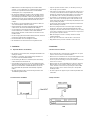
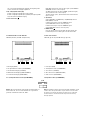
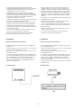
1.3 Monitor multiple connection
Up to 3 monitors can be connected using the loop-through feature of
this unit. When the monitor is connected to additional monitors, the
same picture can be obtained on all the connected monitors.
1.3 Anschluss mehrerer Monitore
Bei Benutzung des Video - Durchschleifeinganges (VIDEO IN / OUT)
können bis zu drei Monitore angeschlossen werden.
2. Starting / Operation
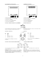
The following controls are located on the frontside on the monitor.
2.1 Monitor Setting / Controls VMC-10/2
2. Inbetriebnahme / Bedienung
Die Einstell-Regler befinden sich auf der Vorderseite des Monitors.
2.1 Monitoreinstellung VMC-10/2
1 Lautstärke - Regler (VOLUME)
Zur Erhöhung der Lautstärke das Reglerrad nach links, zur Absen-
kung nach rechts drehen. Ist der Audio - Eingang nicht belegt, das
Rändelrad ganz nach rechts drehen.
2 Kontrast - Regler (CONTRAST)
Zur Erhöhung des S/W - Kontrastes das Reglerrad nach links, zur
Absenkung nach rechts drehen.
3 Helligkeits - Regler (BRIGHT)
Zur Erhöhung der Grundhelligkeit das Reglerrad nach links, zur
Absenkung nach rechts drehen.
4 Farbkontrast - Regler (COLOR)
Zur Erhöhung der Farbsättigung das Reglerrad nach links, zur Absen-
kung nach rechts drehen.
5 TINT - Regler (TINT)
Beim Drehen des Reglers nach links wird die Hautfarbe grünlich, beim
Drehen nach rechts wird die Hautfarbe rötlich (wirksam nur bei NTSC-
Signalen).
6 A/B - Betriebsanzeige (A/B)
Die obere grüne LED leuchtet, wenn der Eingang A, die untere grüne,
wenn der Eingang B angewählt wurde.
1 VOLUME control
Adjust the Volume control for the appropriate audio level. Turn
clockwise to increase sound and counterclockwise to decrease it. If
the audio input is not used turn to minimum.
2 CONTRAST control
Adjust the Contrast control for the desired overall contrast. Turn
clockwise to increase picture contrast and counterclockwise to
decrease it.
3 BRIGHT control
Adjust the Bright control for the desired overall picture or display
brightness. Turn clockwise for more brightness and counterclockwise
for less.
4 COLOUR control
Adjust the Colour control to set the colour (saturation) level. When
turned counterclockwise, the colour seems pale (low colour). When
turned clockwise, the colour seems saturated (high colour).
5 TINT control
Adjust the Tint control for the proper colour phase or flesh tone. When
turned counterclockwise, the skin tone become greenish. When
turned clockwise, the skin tone become reddish (operation in NTSC
mode only).

5
7 A/B - Eingangswahlschalter (A/B)
Umschaltung auf die FBAS - Eingänge A oder B. Der Y/C - Schalter ist
auf „AUS“ zu stellen.
8 Y/C - Wahlschalter (YC)
Umschaltung auf den Y/C - Eingang.
9 Y/C - Betriebsanzeige
Die untere grüne LED leuchtet, wenn der Y/C - Eingang angewählt
wurde.
10 Netz - Schalter
Geräte Ein- / Ausschaltung.
6 A/B Indicator
The upper green LED will be indicated when the VIDEO A is selected.
The lower green LED will be indicated when the VIDEO B is selected.
7 A/B Selector
Set the selector to A (VIDEO-IN A) or B (VIDEO-IN B) of the compo-
site video input via the VIDEO A IN / VIDEO B IN connector of
the rear panel.
The Y/C selector is set to OFF state.
8 Y/C Selector
Set the selector to ON state, when monitoring a Y/C signal (S-VIDEO,
separated Y/C signal) via the Y/C IN connector on the rear panel.
9 Y/C Indicator
The lower green LED will be indicated, when the Y/C is selected.
10 POWER switch
Press the switch to turn the monitor ON. (The input indicator will be
illuminated.) Press the switch again to turn the monitor OFF.
A/B YC
VIDEO A
AUS / OFF AUS / OFF
VIDEO B
EIN / ON AUS / OFF
Y/C
EIN-AUS / ON-OFF EIN / ON
Selector Description
Note: ON/OFF means „Don’t care” state of the selector.
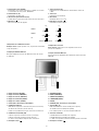
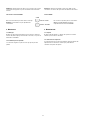
2.2 Monitor Setting / Controls VMC-14/2
Function of the controls see VMC-10/2
Eingangswahlschalter - Konfigurationen
Hinweis: EIN/AUS bedeutet, dass in diesem Fall die Schalterstellung
ohne Bedeutung ist.
2.2 Monitoreinstellung VMC-14/2
Beschreibung zur Funktion der einzelnen Regler: s. VMC-10/2
2
1
3
4
8
9
7
5
6
1 Lautstärke - Regler (VOLUME)
2 Schärfe (SHARPNESS)
3 Kontrast - Regler (CONTRAST)
4 Helligkeits - Regler (BRIGHT)
5 Farbkontrast - Regler (COLOUR)
6 Tönung (TINT, nur bei NTSC-Signalen)
7 CVBS - Y/C - Wahlschalter
CVBS: FBAS - Eingang A oder B angewählt (Taste nicht gedrückt)
1 VOLUME control
2 SHARPNESS control
3 CONTRAST control
4 BRIGHT control
5 COLOUR control
6 TINT control (NTSC only)
7 CVBS, Y/C Selector
Set the SELECTOR to CVBS (composite video) or Y/C for video input.

6
CVBS: When monitoring a composite video signal. (via the VIDEO A /
VIDEO B IN connector on the rear panel.)
Y/C: When monitoring a Y/C signal (S-VIDEO, separated Y/C signal,
via the Y/C IN connector on the rear panel.)
The input indicator (Y/C, A, B) will iluminate when the desired video
input is selected.
8 A/B Selector
Set the SELECTOR to A (VIDEO A IN) or B (VIDEO B IN) when the
CVBS (VIDEO) is selected.
A: When monitoring the composite VIDEO A IN signal.
(via the VIDEO A IN connector on the rear panel.)
B: When monitoring the composite VIDEO B IN signal.
(via the VIDEO B IN connector on the rear panel.)
9 POWER switch
Press the switch to turn the monitor ON. (The input indicator will
be illuminated.) Press the switch again to turn the monitor OFF.
Y/C: Y/C - Eingang angewählt (Taste gedrückt). Die zugehörige LED
leuchtet, wenn der Y/C - Eingang angewählt ist.
8 A/B - Eingangswahlschalter (A/B)
A: FBAS - Eingang A angewählt (Taste nicht gedrückt)
B: FBAS - Eingang B angewählt (Taste gedrückt) Die zugehörige LED’s
zeigen den jeweils angewählten Eingang.
9 Netz - Ein Schalter
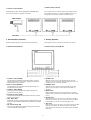
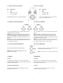
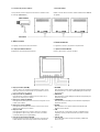
2.3 Rear side connectors
VMC-10/2 (fig. left side) and VMC-14/2 (fig. right side)
2.3 Monitoranschlüsse auf der Rückseite
VMC-10/2 (Bild links) und VMC-14/2 (Bild rechts)
2
1
543
4
53
2
1
1. Power input (AC/IN)
2. Y/C-Impedance switch (Y/C IMPEDANCE)
3. Y/C-connector (Y/C IN/OUT)
4. Video A/B connector (VIDEO A/B IN/OUT)
5. Audio connector (AUDIO IN/OUT)
Y/C-Impedance switch (Y/C IMPEDANCE)
1. Netzeingang (AC/IN)
2. Y/C-Signalabschluss-Schalter (Y/C IMPEDANCE)
3. Y/C-Durchschleifeingang (Y/C IN/OUT)
4. FBAS-Durchschleifeingänge (VIDEO A/B IN/OUT)
5. Ton-Durchschleifeingang (AUDIO IN/OUT)
zu 2. Y/C-Signalabschluss-Schalter (Y/C IMPEDANCE)
Y/C
IMPEDANCE
HIGH 75 Ω
Hinweis: Bei nur einem Monitor, bzw. am Ende einer Monitorkette, ist
dieser Schalter auf „75 Ω” zu stellen. Wird das Y/C - Signal durch-
geschleift, stellt man den Schalter auf „HIGH”.
Note: The impedance switch selects the S-VHS Video impedance. Set the
switch to the to 75 Ω position when only one monitor is used or when
the monitor is used as the last monitor in a chain. Set to „high” when
another monitor is connected to the Y/C output connector for loop-
through operation.

7
zu 3. Y/C-Durchschleifeingang (Y/C IN/OUT) Y/C-Connector (Y/C IN/OUT)
PIN Beschreibung
1 Masse
2 Masse
3 Y Ein-/ oder Ausgang
4 Ein-/ oder Ausgang
Zwei Mini-DIN Buchsen für den Y/C-Durchschleifeingang
PIN Description
1 GND
2 GND
3 Y Signal IN or OUT
4 C Signal IN or OUT
There are two Mini-DIN connectors for the Y/C in/out
for looping to other video monitors.
Video A/B connector (VIDEO A/B)zu 4. FBAS-Durchschleifeingänge (VIDEO A/B)
There are four BNC connectors for the composite video A/B inputs and
outputs.
Note: The impedance is automatically set to 75 Ω (by the input of a
signal on the input connector while operating in a single connection
mode. However, if a cable is connected to the output connector, the
connection is placed into the open status by the multiple connection and
high impedance automatically selected.
Caution: do not leave an unusual cable connected to the monitor. If a
single cable is used then it must be connected to the input connector for
the 75 Ω auto-termination selector to function properly.
Audio connector (AUDIO IN/OUT)
An insgesamt vier BNC-Buchsen können 2 FBAS-Signale im Durch-
schleifbetrieb angeschlossen werden.
Hinweis: Wird jeweils nur die Eingangsbuchse (IN) belegt, erfolgt ein
automatischer 75 Ω-Abschluss. Der Anschluss eines Kabels am
Durchschleifeingang (OUT) bewirkt jedoch die Aufhebung des 75 Ω-
Abschlusses und ermöglicht so den Durchschleifbetrieb zu weiteren
Monitoren.
Achtung: Niemals ein Kabel am Durchschleifausgang aufstecken, ohne
dass es zu einem weiteren Geräte-Eingang geführt wird, dies führt zu
einer Fehlfunktion des Monitors.
zu 5. Ton-Durchschleifeingang (AUDIO IN/OUT)
Zwei Cinch-Buchsen für den Ton-Durchschleifbetrieb.
Hinweis: Der Ton-Eingang kann unabhängig von den Video-
Eingängen betrieben werden.
There are two Cinch type connectors for the Audio in/out for
looping through to other video monitors.
Note: The Audio in/out does not depend on the Video inputs.
3. Maintenance
3.1 Cleaning
Clean the unit with a slightly damp soft cloth. Use a mild household
detergent. Never use strong solvents such as thinner or benzine as they
might damage the finish of the units.
3.2 Services
To prevent electric shock, do not remove screws or cover. Refer
servicing to qualified service personnel.
3. Wartung
3.1 Pflege
Zu Reinigung des Gerätegehäuse nur ein mildes Haushaltsmittel
verwenden. Niemals mit Verdünner oder Benzin reinigen. Dies kann die
Oberfläche dauerhaft schädigen.
3.2 Hinweis auf Reparaturdienste
Den Deckel des Gerätes nicht öffnen. Instandsetzung nur durch
qualifiziertes Servicepersonal.

8
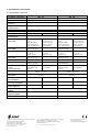
4. Spezifikationen / Specifications
4.1 Technische Daten / Technical data
Farb-Monitor / Colour Monitor VMC - 10/2 VMC - 14/2
Modell / Model VMC-10/2 VMC 14/2
EDV-Nr. / EDP no. 90363 90351
Bildschirm-Diagonale / 10” 14”
Screen size
Sichtbare Schirmdiagonale / 24 cm 34 cm
Visible screen size
Bildröhre / Picture Tube 0,63 mm DOT Pitch 0.63 mm DOT Pitch 0,66 mm DOT Pitch 0.66 mm DOT Pitch
Ablenkung / Deflection 90° 90°
Auflösung / Resolution > 280 TV-Linien (PAL) > 280 TV Lines (PAL) > 350 TV-Linien (PAL) > 350 TV-Lines (PAL)
(PAL)Video Norm / PAL / NTSC PAL / NTSC
System Standard
Video Eingänge A/B / Video A/B: Video A/B: Video A/B: Video A/B:
Video in A/B 2x1 Vss / composite video 1.0 2x1 Vss / composite video 1.0
75 Ω, FBAS, (BNC) Vp-p (at 75 Ω), Sync 75 Ω, FBAS, (BNC) Vp-p (at 75 Ω), Sync
positiv, asymmetrisch negative, automatic positiv, asymmetrisch negative, automatic
autom. 75 Ω-Abschluss 75 Ω termination autom. 75 Ω-Abschluss 75 Ω termination
Video Ausgänge A/B / Passive Loop-through outputs Passive Loop-through outputs
Video out A/B Durchschleifausgänge Durchschleifausgänge
Video Eingang / Video in Y/C Y -Signal 1 Vss Y Signal: 1 Vp-p Y -Signal: 1 Vss Y Signal: 1 Vp-p
Vss / 75 Ω Vp-p / 75 Ω; Vss / 75 Ω Vp-p / 75 Ω;
C-Signal: 0,3 Vss C Signal: 0.3 Vp-p C-Signal: 0,3 Vss C Signal: 0.3 Vp-p
Video Ausgang Y/C / Passiver Loop-through output Passiver Loop-through output
Video out Y/C Durchschleifausgang Durchschleifausgang
Audio Eingang / Audio in 300 mVss, > 47 kΩ 300 mVp-p, > 47 kΩ 300 mVss, > 47 kΩ 300 mVp-p, > 47 kΩ
Audio Ausgang / Audio out Passiver Loop-through output Passiver Loop-through output
Durchschleifausgang Durchschleifausgang
Anschluss Video A / B 4 x BNC-Buchse, 4 x BNC socket, 4 x BNC-Buchse, 4 x BNC socket,
in / out automatischer 75 Ω auto termination automatischer 75 Ω auto termination
Connector Video A / B Abschluss Abschluss
Linearität / Linearity Horizontal: 10% max Horizontal: 10% max
Vertikal: 10% max Vertikal: 10% max
Spannungsversorgung / 90-132 VAC, 198-254 VAC 90-132 VAC, 198-254 VAC
Power Source 50 / 60 Hz 50 / 60 Hz
Leistungsaufnahme / 55 W 55 Watts 70 W 70 Watts
Power consumption
Leistung / Lautsprecher / 1 W 1 Watt 1 W 1 Watt
Power cons. loudspeaker
Umgebungstemperatur / 0°C bis +40°C0°C to + 40°C0°C bis +40°C0°C to + 40°C
Ambient temperature
Rel. Luftfeuchte im Raum / 10 - 90 % 10 - 90 %
Humidity
Abmessungen (BxHxT) / 260 x 245 x 338 mm 350 x 330 x 375 mm
Dimensions (WxHxD)
Gewicht / Weight 10 kg 14 kg
Technische Änderungen vorbehalten.
Technical changes reserved.
© Copyright by VIDEOR TECHNICAL 04/01
eneo
®
ist eine eingetragene Marke der Videor Technical E. Hartig GmbH
Vertrieb ausschließlich über den Fachhandel.
VIDEOR TECHNICAL E. Hartig GmbH
Maybachstraße 5 · D-63322 Rödermark/Germany
Tel. (0 60 74) 888-0 · Fax. (0 60 74) 888-100
www.eneo-security.com
eneo
®
is a registered trademark of Videor Technical E. Hartig GmbH
VIDEOR TECHNICAL E. Hartig GmbH (U.K. Branch)
Unit 14, Campbell Court · Campbell Road, Bramley, Tadley
GB-Hampshire RG26 5EG
Tel. (0 12 56) 88 02 20 · Fax. (0 12 56) 88 00 89
Seite wird geladen ...
Seite wird geladen ...
Seite wird geladen ...
Seite wird geladen ...
Seite wird geladen ...
Seite wird geladen ...
Seite wird geladen ...
Seite wird geladen ...
-
 1
1
-
 2
2
-
 3
3
-
 4
4
-
 5
5
-
 6
6
-
 7
7
-
 8
8
-
 9
9
-
 10
10
-
 11
11
-
 12
12
-
 13
13
-
 14
14
-
 15
15
-
 16
16


Eneo VMC-10/2 Operating Instructions Manual
- Typ
- Operating Instructions Manual
- Dieses Handbuch eignet sich auch für
in anderen Sprachen
- English: Eneo VMC-10/2
- français: Eneo VMC-10/2
- español: Eneo VMC-10/2
Verwandte Artikel
-
Eneo VMC-19LCD-HMC1 Installation And Operating Instructions Manual
-
-
-
-
-
-
-
-
-
Andere Dokumente
-
Philips 14-COLOR MONITOR-RECEIVER 14RF50S Bedienungsanleitung
-
 American Dynamics AD9421 Benutzerhandbuch
-
 American Dynamics AD9414 Benutzerhandbuch
-
Panasonic WVCM1430 Bedienungsanleitung
-
Samsung AD9421A Bedienungsanleitung
-
-
Grundig DAVIO 37 P 37-4201 TOP Benutzerhandbuch

