3B SCIENTIFIC 1000817 [U8440450] Bedienungsanleitung
- Typ
- Bedienungsanleitung

3B SCIENTIFIC® PHYSICS
1
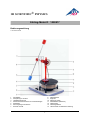
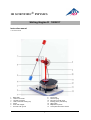
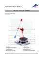
Stirling-Motor D 1000817
Bedienungsanleitung
11/23 THL/ALF/UD
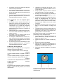
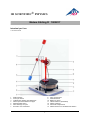
1 Grundplatte
2 Aussparung für Teelicht
3 Heizplattenanschluss
4 Schlauchanschlussstutzen mit Verschlusskappe
5 Stativsäule
6 Schwungstange mit Massen
7 Exzenter mit Nut
8 Winkelscheibe
9 Zugfeder
10 Pleuel mit Haken
11 Arbeitskolben (Membran)
12 Obere Platte
13 Verdrängerkolben
14 Untere Platte mit elektrischer Heizung

2
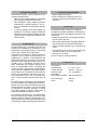
1. Sicherheitshinweise
Beim Arbeiten mit offener Flamme besteht
Brand- und Verletzungsgefahr!
Beim Umgang mit offener Flamme und flüs-
sigem Wachs besondere Vorsicht walten
lassen.
Der Stirling-Motor darf nicht gleichzeitig
elektrisch und mit Teelicht beheizt werden.
Dies kann zur Beschädigung des Geräts
führen.
Bei Betrieb des Stirling-Motors mit einem
Spotlight oder Sonnenlicht ist unbedingt da-
rauf zu achten, dass die roten Kunststoff-
teile nicht intensiver Wärmestrahlung aus-
gesetzt werden.
2. Beschreibung
Der Stirling-Motor D ist ein für den Unterricht op-
timiertes Funktionsmodell zur Demonstration
der Umwandlung von thermischer Energie in
mechanische Energie sowie zur Untersuchung
des Stirling’schen Kreisprozesses.
Der Verdrängerkolben bewegt sich diskontinu-
ierlich mit einer Verweilzeit während der Erwär-
mung und während der Abkühlung des Arbeits-
mediums Luft. Dadurch wird der ideale Stir-
ling’sche Kreisprozess besser ausgefahren als
dies bei kontinuierlicher Kolbenbewegung der
Fall wäre und es wird ein höherer Wirkungsgrad
erreicht. Die Steuerung des Verdrängerkolbens
erfolgt über die Winkelscheibe. Bei Wärmezu-
fuhr von unten über die Heizplatte oder eine
Kerzenflamme eilt der Verdrängerkolben dem
Arbeitskolben (Membran) um ca. 100° voraus.
Der optimale Winkel ist technisch bedingt dreh-
zahlabhängig.
Zur Wärmezufuhr kann wahlweise eine inte-
grierte elektrische Heizplatte, ein Teelicht oder
die gebündelte Wärmestrahlung der Sonne
bzw. einer Lampe genutzt werden. Dabei hängt
die Drehrichtung davon ab, ob die Wärmezufuhr
von oben oder von unten erfolgt.
Zur Aufnahme von pV-Diagrammen kann die
Druckmessung im Arbeitszylinder über einen
Schlauchanschlussstutzen bewerkstelligt wer-
den und die Volumenbestimmung durch Befes-
tigen eines Fadens am Haken des Pleuels zur
Messung des Hubweges des Arbeitskolbens.
3. Lieferumfang
1 Stirling-Motor D 1000817
1 Satz Transportsicherung (Schaumstoffblock,
Gummiring und Arretierstab)
4. Zubehör
Ergänzungssatz Stirling-Motor D (1008516)
Der Ergänzungssatz Stirling-Motor D stellt die
Zubehörteile bereit, die zum Aufbau der Senso-
ren nötig sind. Der Satz besteht aus:
1 Auflageplatte für die Montage des Wegauf-
nehmers (1021534)
1 Rändelschraube zur Befestigung der Auflage-
platte auf der Stativsäule
1 Stiel mit Magnetfuß für den Wegaufnehmer
1 Silikonschlauch zum Anschluss des Relativ-
drucksensors (1021532)
1 Fadenset mit Saugnapf
2 Massestücke mit Haken je 20 g
5. Technische Daten
Heizspannung: 8 – 15 V, 1,5 A
Gasvolumen: 330 cm³ – 345 cm³
Drehzahl: 30 – 100 U/min
Abmessungen ohne
Schwungstange: 260×185×330 mm³
Schwungstange: 400 mm
Masse: 2,2 kg

3
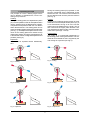
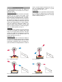
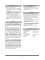
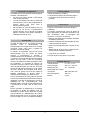
6. Funktionsprinzip
Die Funktionsweise des Stirling-Motors kann ver-
einfachend in die folgenden vier Takte unterteilt
werden:
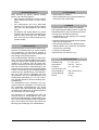
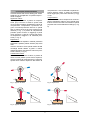
Wärmezufuhr:
Zur Wärmezufuhr bewegt sich der Verdränger-
kolben (P1) aufwärts und verdrängt die Luft
nach unten in den geheizten Bereich des Ver-
drängungszylinders. Temperatur und Druck
steigen annähernd isochor an. Der Arbeitskol-
ben befindet sich währenddessen im unteren
Totpunkt (siehe Fig. 1). Der Verdrängerkolben
läuft dem Arbeitskolben vorraus und erreicht
den oberen Totpunkt. Die Luft hat nun das
kleinste Volumen, die höchste Temperatur und
den höchsten Druck (siehe Fig. 2).
Expansion:
Die erwärmte Luft expandiert annähernd iso-
therm und treibt den Arbeitskolben (P2) nach
oben. Dabei wird mechanische Arbeit über die
Kurbelwelle an die Schwungstange abgegeben.
Das Luftvolumen wird größer, die Luft nimmt
Wärme auf und der Druck verringert sich (siehe
Fig. 3).
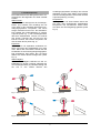
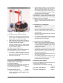
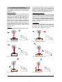
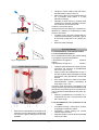
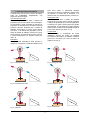
Wärmeabgabe:
Bei der Wärmeabgabe befindet sich der Ar-
beitskolben im oberen Totpunkt, während sich
der Verdrängerkolben (P1) abwärts bewegt und
die Luft in den oberen Bereich des
Verdrängungszylinders verdrängt. Die Luft wird
abgekühlt und die obere Platte nimmt Wärme
auf. Der Verdrängerkolben erreicht den unteren
Totpunkt (siehe Fig. 4 und 5).
Kompression:
Die abgekühlte Luft wird isotherm durch den
sich nach unten bewegenden Arbeitskolben
komprimiert. Die mechanische Arbeit hierfür
wird durch die Schwungstange geliefert (siehe
Fig. 6).
Fig. 1: Wärmezufuhr
Fig. 2: Wärmezufuhr
Fig. 3: Expansion
Fig. 4: Wärmeabgabe
P
V
P1
P
V
P
V
P2
P
V
P1

4
Fig. 5: Wärmeabgabe
Fig. 6: Kompression
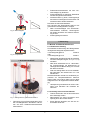
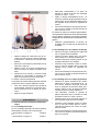
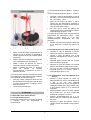
7. Erstinbetriebnahme
Fig. 7: Stirling-Motor in gesichertem Zustand
Gummiring (3) vom Sicherungshaken (4) für
den Verdrängerkolben abnehmen und Ha-
ken aus dem Schlauchanschlussstutzen
herausziehen.
Schlauchanschlussstutzen mit roter Ver-
schlusskappe (5) abdichten.
Schaumstoffblock (2) zwischen Stativsäule
und Schwungmasse entnehmen.
Arretierschraube (1) lösen, Schwungstange
horizontal im Gleichgewicht ausrichten und
Arretierschraube wieder festziehen.
Der Motor ist damit betriebsbereit.
Der Transport des Stirling-Motors darf nur mit
gesichertem Verdrängerkolben erfolgen.
Dazu Verschlusskappe vom Schlauchan-
schlussstutzen entfernen, Sicherungsha-
ken wieder einsetzen und mit dem Gummi-
ring sichern.
Schwungstange arretieren.
8. Bedienung
8.1 Betrieb als Wärmekraftmaschine
8.1.1 Elektrische Heizung
Zur elektrischen Beheizung des Stirling-Motors
ist folgendes Netzgerät empfehlenswert:
1 DC-Netzgerät @230 V 1003312
oder
1 DC-Netzgerät @115 V 1003311
Netzgerät an das Buchsenpaar anschließen
und eine Heizspannung bis 12 V (ca. 1,5 A)
einstellen.
Nach einer Aufheizzeit von ca. 1 bis 2 Minu-
ten Schwungstange mit Drehrichtung im
Uhrzeigersinn bei Blickrichtung von vorn auf
den Motor anstoßen.
Falls der Stirling-Motor sich nicht selbstän-
dig weiterdreht, den Anstoß nach ca. 1 min
wiederholen.
Die Motordrehzahl verhält sich annähernd pro-
portional zur Temperaturdifferenz zwischen
oberer Platte und unterer Platte und ist damit
weitgehend von der zugeführten Wärme abhän-
gig.
Heizspannung schrittweise bis auf 8 V redu-
zieren und Abnahme der Drehzahl be-
obachten.
8.1.2 Heizung mit einer Kerzenflamme
Teelicht entzünden und auf eine hitzeresis-
tente Unterlage stellen.
Stirling-Motor mit seiner zentrischen Aus-
sparung über das Teelicht stellen.
Einige Minuten abwarten, bis sich die un-
tere Platte erhitzt hat.
P
V
P
V
P2

5
Schwungstange mit Drehrichtung im Uhr-
zeigersinn bei Blickrichtung von vorn auf
den Motor anstoßen.
Falls der Stirling Motor sich nicht selbstän-
dig weiterdreht, den Anstoß nach ca. 1 min
wiederholen.
8.1.3 Heizung mit einer Lampe (Spotlight)
Obere Platte des Stirling-Motors von oben
aus einer Entfernung von 1 bis 2 cm einer
60-W-Glühlampe mit eingeschränktem Ab-
strahlwinkel (Spotlight) bestrahlen. Die un-
tere Platte kühlt in diesem Falle die Luft im
Verdrängerzylinder ab.
Alternativ die obere Platte mit durch einen
Hohlspiegel gebündeltes Sonnenlicht be-
heizen.
Etwa 8 bis 10 Minuten abwarten, bis sich die
obere Platte erhitzt hat.
Schwungstange mit Drehrichtung gegen
den Urzeigerrichtung bei Blickrichtung von
vorn auf den Motor anstoßen.
Falls der Stirling-Motor sich nicht selbstän-
dig weiterdreht, den Anstoß nach einiger
Zeit wiederholen.
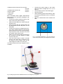
8.2 Aufnahme des pV-Diagramms
Zur Aufnahme des pV-Diagramms sind fol-
gende Geräte zusätzlich erforderlich:
1 Ergänzungssatz Stirling-Motor D 1008516
1 DC-Netzgerät @230 V 1003312
oder
1 DC-Netzgerät @115 V 1003311
1 Relativdrucksensor FW ±100 hPa 1021532
1 Wegaufnehmer FW 1021534
2 Sensorkabel 1021514
1 Datenlogger
1 Software
Weitere Informationen zum digitalen Messen
sind auf der Webseite des Produkts im 3B
Webshop zu finden
Relativdrucksensor mit dem Silikon-
schlauch an den Schlauchanschlussstutzen
anschließen.
Auflageplatte mit der Rändelschraube auf
der Stativsäule befestigen.
Stiel mit Magnetfuß in den Wegaufnehmer
schrauben und auf die Auflageplatte platzie-
ren.
Schraube an der Rolle des Wegaufnehmers
lösen. Faden ein Mal um die Rolle legen,
aus der Aussparung herausführen und eine
Schlaufe um die Schraube legen. Mit der
Schraube den Faden fixieren (siehe Fig. 8).
Das eine Ende des Fadens am Pleuelhaken
befestigen, ans andere Ende ein Masse-
stück hängen.
Einen zweiten Faden mittels des Saugnapfs
auf der Grundplatte befestigen. Faden über
die Nut im Exzenter legen und das zweite
Massestück ans freie Ende hängen.
Dieses Massestück dient als Last und sorgt da-
für, dass das pV-Diagramm besser ausgefah-
ren wird.
Netzgerät an die Heizplatte anschließen
und eine Spannung bis 12 V (ca. 1,5 A) ein-
stellen.
Beide Sensoren an den Datenlogger an-
schließen.
Software starten.
Nach der Aufwärmzeit den Stirling-Motor
durch Anstoßen im Uhrzeigersinn starten.
Messung starten. Daten auswerten.
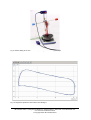
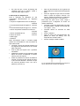
Fig. 8: Schematische Darstellung der Führung des
Fadens um die Rolle am Wegaufnehmer

3B Scientific GmbH Ludwig-Erhard-Straße 20 20459 Hamburg Deutschland www.3bscientific.com
Technische Änderungen vorbehalten
© Copyright 2023 3B Scientific GmbH
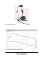
Fig. 9: Stirling-Motor D mit installierten Sensoren zur Aufnahme des pV-Diagramms
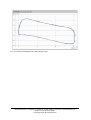
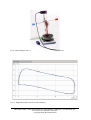
Fig. 10: Druck-Volumen-Diagramm des Stirling-Motors D

3B SCIENTIFIC® PHYSICS
1
Stirling Engine D 1000817
Instruction manual
11/23 THL/ALF/UD
1 Base plate
2 Hole for tea candle
3 Hot plate connector
4 Hose nozzle with sealing cap
5 Stand
6 Rotor with weights
7 Eccentric with groove
8 Torque disc
9 Tension spring
10 Connector rod with hook
11 Working piston (membrane)
12 Upper plate
13 Displacement piston
14 Lower plate with electric heater

2
1. Safety instructions
When working with naked flames, there is al-
ways a risk of fire and injury.
Take extra care when handling naked
flames and molten wax.
The Stirling engine may not be heated elec-
trically at the same time as it is being heated
by a candle. There is a risk of damage to the
equipment.
When operating the Stirling engine using a
spotlight or sunlight, it is essential that care
be taken not to expose the red plastic com-
ponents to intense heat.
2. Description
The Stirling engine D is a fully functional model,
optimised for teaching purposes and intended
to demonstrate how thermal energy can be con-
verted to mechanical energy as well as for in-
vestigating the Stirling cycle.
The displacement piston moves discontinuously
with a delay during heating and cooling of the
working medium, air. This emulates the ideal
Stirling cycle better than would be the case with
a continuously moving piston and also makes
for improved efficiency. The motion of the dis-
placement piston is controlled by the torque
disc. When heat is supplied from below, either
by means of the electric heater or by a candle
flame, the displacement piston precedes the
working piston (membrane) by about 100°. The
optimum angle is technically dependent on the
speed of rotation.
Heat can be supplied either by the built-in elec-
tric hot plate, a candle or by focussed heat radi-
ation from the sun or by a lamp. The direction of
rotation depends on whether the heat is sup-
plied from above or below.
To record pV diagrams, the pressure in the
working cylinder can be measured by means of
a hose attached to the nozzle provided and the
volume can be determined by attaching a
thread to the hook on the connecting rod in or-
der to measure the stroke of the working piston.
3. Scope of delivery
1 D-series Stirling engine 1000817
1 Set of transport packaging (foam plastic
block, rubber band and retaining rod)
4. Accessories
Supplementary set for Stirling engine D
(1008516)
The supplementary set for the Stirling engine D
provides accessories necessary for construct-
ing sensors. The set consists of the following:
1 Base plate for assembly of displacement
sensor (1021534)
1 Knurled screw for attaching the base plate to
the stand
1 Stem with a magnetic base for the displace-
ment sensor
1 Silicone tube for attaching the relative pres-
sure sensor (1021532)
1 Set of threads with suction cup
2 Weights with hook, both 20 g
5. Technical data
Heater voltage: 8 – 15 V, 1.5 A
Gas volume: 330 cm³ – 345 cm³
Speed: 30 – 100 rpm
Dimensions
not including rotor: 260×185×330 mm3
Rotor: 400 mm
Weight: 2.2 kg

3
6. Operating principle
The principle of a how a Stirling engine works
can be divided, in simplified form, into the fol-
lowing four processes:
Heating:
During the heating phase, the displacement piston
(P1) moves upwards so that air is displaced down
into the heated part of the displacement cylinder.
Temperature and pressure both rise in a fashion
that is almost isochoric. The working piston is in its
lower rest position (bottom dead centre) at this point
(see Fig. 1). The displacement piston moves in ad-
vance of the working piston till it reaches its top
dead centre position. This is the point where the air
is at its lowest volume, but highest temperature and
pressure (see Fig. 2).
Expansion:
The heated air expands almost isothermally,
thus
forcing the working piston (P2) upwards. In the
process, mechanical work is transferred via the
shaft to the rotor. The volume of air increases as
the air absorbs heat and the pressure reduces
(see Fig. 3).
Cooling:
Cooling occurs while the working piston is at top
dead centre and the displacement piston (P1) is
on its downstroke, forcing air to move into the
upper part of the displacement cylinder. The air
then cools and the upper plate absorbs heat.
The displacement piston finally reaches bottom
dead centre (see Figs. 4 and 5).
Compression:
The cooler air is compressed isothermally by
the working piston moving downwards. The me-
chanical work needed for this is supplied by the
rotor acting as a flywheel (see Fig. 6).
Fig. 1: Heating
Fig. 2: Heating
Fig. 3: Expansion
Fig. 4: Cooling
Fig. 5: Cooling
Fig. 6: Compression
P
V
P1
P
V
P
V
P2
P
V
P1
P
V
P
V
P2

4
7. Getting the engine ready for use
Fig. 7: Stirling engine as secured for storage
Remove the rubber band (3) from the secur-
ing hook (4) for the displacement piston and
take the hook out of the hose nozzle.
Seal off the hose nozzle with the red cap (5).
Remove the foam plastic block (2) between
the stand and the rotor weight.
Undo the securing screw (1), align the rotor
horizontally so that it is balanced and tighten
the screw back up again.
The engine is then ready for use.
The Stirling engine must not be transported un-
less the displacement piston is secured.
To secure it, take the sealing cap of the
hose nozzle, put the securing hook back in
and secure it in place with the rubber band.
Secure the rotor as well.
8. Operation
8.1 Operation as a heat engine
8.1.1 Electric heating
The following power supplies are recommended
for heating the Stirling engine electrically:
1 DC power supply @230 V 1003312
or
1 DC power supply @115 V 1003311
Connect the power supply to the pair of
sockets and set the heater voltage up to 12
V (1.5 A approx.).
After heating for about one or two minutes,
start the engine by pushing the rotor clock-
wise as seen from the front of the engine.
If the Stirling engine fails to keep moving of
its own accord, wait about a minute longer
and push the rotor round again.
The speed of the engine is nearly proportional
to the difference in temperature between the top
plate and the bottom plate and is thus largely
dependent on the heat supplied.
Reduce the heater voltage in steps down to
about 8 V and observe how the speed re-
duces.
8.1.2 Heating via a candle flame
Light a tea candle and place it on a heat-
resistant mat.
Place the Stirling engine over the candle so
the hole in the middle is over the flame.
Wait for several minutes until the lower plate
has heated up.
Push the rotor clockwise as seen from the
front of the engine.
If the Stirling engine fails to keep moving of
its own accord, wait about a minute longer
and push the rotor round again.
8.1.3 Heating via a lamp (spotlight)
Shine a light on the top plate from about 1
or 2 cm using a lamp with a 60-W bulb and
a focussed beam (spotlight). In this case it
is the lower plate that will cool the air in the
displacement cylinder.
Alternatively, the upper plate can be heated
via sunlight focused using a concave mirror.
Wait for about 8 to 10 minutes until the up-
per plate has heated up.
Push the rotor anti-clockwise as seen from
the front of the engine.
If the Stirling engine fails to keep moving of
its own accord, wait about a minute longer
and push the rotor round again.
8.2 Recording a pV diagram
To record a pV diagram, the following pieces of
equipment are also required:
1 Supplementary set for Stirling engine D
1008516
1 DC power supply @230 V 1003312
or
1 DC power supply @115 V 1003311

5
1 Relative Pressure Sensor FW ±100 hPa
1021532
1 Displacement Sensor FW 1021534
2 Sensor Cables 1021514
1 Data logger
1 Software
More information about digital measurement
can be found on the product's webpage in the
3B Webshop.
Connect the relative pressure sensor to the
hose nozzle using silicone tubing.
Attach the base plate to the stand using the
knurled screw.
Screw the stem with the magnetic base into
the displacement sensor and place it on the
base plate.
Loosen the screw on the displacement sen-
sor’s pulley. Wind a thread once around the
pulley and lead it out of the recess placing a
loop around the screw. Use the screw to fix
the thread in place (see Fig. 8).
Attach one end of the thread to the hook of
the connector rod and suspend a weight
from the other end.
Use the suction pad to attach a second
thread to the base plate. Thread this over
the groove in the eccentric and use the
other weight as a load on the free end.
This load ensures that the pV diagram comes
out better.
Connect the power supply to the heater
plate and set the voltage up to 12 V (1.5 A
approx.).
Connect both sensors to the data logger.
Start the software.
After the Stirling engine has heated up, start
it running by pushing the rotor in a clockwise
direction.
Start the measurement and evaluate the
data.
Fig. 8: Schematic illustration of how the thread is
wound around the pulley of the displacement sensor
Fig. 9: Stirling engine D with installed sensors for recording the pV diagram

3B Scientific GmbH ▪ Ludwig-Erhard-Straße 20 ▪ 20459 Hamburg ▪ Germany ▪ www.3bscientific.com
Subject to technical amendments
© Copyright 2023 3B Scientific GmbH
Fig. 10: Pressure-volume diagram for D-series Stirling engine

3B SCIENTIFIC® PHYSICS
1
Motor de Stirling D 1000817
Instrucciones de uso
11/23 THL/ALF/UD
1 Placa base
2 Entalladura para velita
3 Conexión de la placa calefactora
4 Racor de manguera con tapón
5 Columna soporte
6 Barra volante con masas
7 Excéntrica con ranura
8 Disco angular
9 Muelle tensor
10 Biela con gancho
11 Émbolo de trabajo (Membrana)
12 Placa superior
13 Émbolo de desplazamiento
14 Placa inferior con calefactor eléctrico

2
1. Advertencias de seguridad
¡Al trabajar con una llama abierta se corre el
riesgo de quemaduras o lesiones!
¡Es conveniente tener mucho cuidado al
trabajar con una llama abierta y cera líquida
en el mismo lugar!
El motor de Stirling no se debe calentar al
mismo tiempo con la velita y eléctrica-
mente. Esto puede conducir a un daño del
aparato.
Al trabajar con el motor de Stirling y un foco
luminoso (Spotlight) o con luz solar, es ne-
cesario tener en cuenta que las partes de
plástico rojas no queden expuestas a una
radiación calorífica intensa.
2. Descripción
El motor de Stirling D es un modelo funcional
optimizado para demostraciones didácticas de
la conversión de energía térmica en energía
mecánica así como para el estudio del proceso
cíclico de Stirling.
El émbolo de desplazamiento se mueve en
forma discontinua con un tiempo de permanen-
cia durante las fases de calentamiento y enfria-
miento del aire como medio de trabajo. En esta
forma se sigue mejor el proceso ideal de Stirling
contrario al caso de un movimiento continuo del
émbolo y se logra un rendimiento más alto. El
control del émbolo de desplazamiento se rea-
liza por medio de un disco angular. En caso de
una entrada de calor por debajo, el émbolo de
desplazamiento está en avance aprox. 100°
con respecto al émbolo de trabajo (membrana).
El ángulo óptimo depende da las revoluciones
debido a la técnica.
La entrada de calor se puede realizar ya sea por
medio de la placa calefactora integrada, o con
una velita o por medio de la radiación calorífica
solar o de una lámpara. La dirección de rotación
depende de si la entrada de calor se realiza por
arriba o por debajo.
Para el registro del diagrama pV, la medición de
la presión en el cilindro de trabajo se puede lle-
var a cabo a través de un racor de manguera y
la determinación del volumen fijando un hilo en
el gancho de la biela, para medir la carrera del
émbolo de trabajo.
3. Volumen de suministro
1 Motor de Stirling D 1000817
1 Juego de protección en el transporte (Bloque
de gomaespuma, anillo de goma y barra de
enclavamiento)
4. Accesorios
Juego complementario motor de Stirling D
(1008516)
El juego complementario del motor de Stirling
pone a disposición las partes accesorias nece-
sarias para el montaje de los sensores. El juego
se compone de:
1 Una placa de apoyo para el montaje del trans-
ductor de desplazamiento (1021534)
1 Tornillo moleteado para la fijación de la placa
de apoyo en la columna soporte
1 Un mango con pie magnético para el trans-
ductor de desplazamiento
1 Manguera de silicona para el empalme del
sensor de presión relativa ±100 hPa
(1021532)
1 Juego de hilos con ventosa
2 Pesas con gancho c/u de 20 g
5. Datos técnicos
Tensión de calefacción: 8 – 15 V, 1,5 A
Volumen del gas: 330 cm³ – 345 cm³
Revoluciones: 30 – 100 U/min
Dimensiones sin la
barra volante: 260×185×330 mm³
Barra volante: 400 mm
Masa: 2,2 kg

3
6. Principio funcional
El funcionamiento del motor de Stirling se
puede simplificar como dividido en los cuatro si-
guientes tactos:
Absorción de calor:
Para la entrada de calor el émbolo de despla-
zamiento (P1) se mueve hacia arriba y des-
plaza el aire hacia abajo en el espacio calen-
tado del cilindro de desplazamiento. La temper-
atura y la presión aumentan casi isocoramente.
El émbolo de trabajo se encuentra mientras
tanto en el punto muerto inferior (ver Fig. 1). El
émbolo de desplazamiento se mueve adelan-
tado con respecto al émbolo de trabajo y al-
canza el punto muerto superior. El aire tiene
ahora su mínimo volumen, la máxima tempera-
tura y la máxima presión (ver fig. 2).
Expansión:
El aire caliente se expande casi isotermamente
y acciona el émbolo de trabajo (P2) hacia
arriba. Así entrega trabajo mecánico a la barra
volante por medio de la manivela. El volumen
del aire aumenta, el aire absorbe calor y la
presión disminuye (ver fig. 3)
Entrega de calor:
En la entrega de calor el émbolo de trabajo se
encuentra en el punto muerto superior mientras
el émbolo de desplazamiento (P1) se mueve
hacia abajo y desplaza el aire en el espacio su-
perior del cilindro de desplazamiento. El aire se
enfría y la placa superior absorbe calor. El ém-
bolo de desplazamiento alcanza el punto
muerto inferior (ver Figs. 4 y 5).
Compresión:
El aire enfriado es comprimido isotérmicamente
por el émbolo de trabajo que se mueve hacia
abajo. El trabajo mecánico para ello lo entrega
la barra volante (ver fig. 6).
Fig. 1: Absorción de calor
Fig. 2: Absorción de calor
Fig. 3: Expansión
Fig. 4: Entrega de calor
P
V
P1
P
V
P
V
P2
P
V
P1

4
Fig. 5: Entrega de calor
Fig. 6: Compresión
7. Primera puesta en marcha
Fig. 7: Motor de Stirling en estado protegido para el
transporte
Se retira el anillo de goma (3) del gancho de
protección (4) para el émbolo de desplaza-
miento y se retira el gancho del racor de
manguera.
El racor de manguera se obtura con la tapa
de cierre (5) roja.
Se retira el bloque de gomaespuma (2) en-
tre la columna soporte y la masa volante.
Se afloja el tornillo de enclavamiento (1), se
lleva la barra volante a un equilibrio horizontal
y se vuelve a apretar el tornillo de enclava-
miento.
En esta forma el motor está listo para su funcio-
namiento.
El transporte del motor de Stirling se debe rea-
lizar sólo con el émbolo de desplazamiento ase-
gurado.
Para ello se retira la tapa de cierre del racor
de manguera, se vuelve a colocar el gancho
de protección y se asegura con el anillo de
goma.
Se enclava la barra volante.
8. Manejo
8.1 Funcionamiento como máquina térmica
8.1.1 Calefacción eléctrica
Para el calentamiento eléctrico del motor de Stir-
ling se recomienda la siguiente fuente de alimen-
tación:
1 Fuente de alimentación CC @230 V 1003312
resp.
1 Fuente de alimentación CC @115 V 1003311
Se conecta la fuente de alimentación en el
par de casquillos y se fija una tensión de ca-
lentamiento de hasta 12 V (aprox. 1,5 A).
Después de un tiempo de calentamiento de
aprox. 1 a 2 minutos se empuja cuidadosa-
mente la barra volante en dirección de rota-
ción en el sentido de las manecillas del reloj
viendo de frente hacia el motor.
En caso de que el motor de Stirling no siga
girando independientemente se vuelve a
empujar después de aprox. 1 minuto.
Las revoluciones del motor se comportan casi
proporcionalmente a la diferencia de tempera-
tura entre las placas superior e inferior y depen-
den ampliamente de la cantidad de calor sumi-
nistrada.
Se reduce gradualmente la tensión de cale-
facción hasta 8 V y se observa la reducción
de las revoluciones.
8.1.2 Calefacción con la llama de una vela
Se enciende la velita y se coloca sobre una
superficie resistente al calor.
Se coloca el motor de Stirling encima de la
velita centrada en su entalladura.
P
V
P
V
P2

5
Se espera unos minutos hasta que la placa
inferior se haya calentado.
Se empuja cuidadosamente la barra vo-
lante en dirección de rotación en el sentido
de las manecillas del reloj viendo de frente
hacia el motor.
En caso de que el motor de Stirling no siga
girando independientemente se vuelve a
empujar después de aprox. 1 minuto.
8.1.3 Calefacción con una lámpara (Spot-
light)
Se irradia la placa superior del motor de
Stirling por encima con una lámpara incan-
descente de 60 W a una distancia de 1 a 2
centímetros con un ángulo de irradiación
concentrado (Spotlight). En este caso la
placa inferior enfría el aire en el cilindro de
desplazamiento.
Alternativamente se calienta la placa supe-
rior con luz solar enfocada por medio de un
espejo cóncavo.
Se espera de 8 a 10 minutos hasta que la
placa superior se haya calentado.
Se empuja cuidadosamente la barra vo-
lante en dirección de rotación en el sentido
contrario de las manecillas del reloj viendo
de frente hacia el motor.
En caso de que el motor de Stirling no siga
girando independientemente se vuelve a
empujar después de aprox. 1 minuto.
8.2 Registro del diagrama pV
Para el registro del diagrama pV se requieren
además los siguientes aparatos:
1 Juego complementario motor de Stirling D
1008516
1 Fuente de alimentación CC @230 V 1003312
resp.
1 Fuente de alimentación CC @115 V 1003311
1 Sensor de presión relativa FW ±100 hPa
1021532
1 Transductor de desplazamiento FW 1021534
2 Cables de sensor 1021514
1 Data logger
1 Software
Encontrará más información sobre la medición
digital en el sitio web del producto, en la tienda
virtual de 3B.
Utilizando la manguera de silicona se co-
necta el sensor de presión relativa en el ra-
cor de manguera.
Se fija la placa de apoyo sobre la columna
soporte utilizando el tornillo moleteado.
El mango con pie magnético se atornilla en
el transductor de desplazamiento y se co-
loca en la placa de apoyo.
Se afloja el tornillo en la roldana del trans-
ductor de desplazamiento. Se le da una
vuelta al hilo alrededor de la roldana, se
saca de la ranura y se hace un lazo alrede-
dor del tornillo. Se fija el hilo con el tornillo
(ver fig. 8).
El extremo del hilo se fija en el gancho de la
biela, en el otro extremo se cuelga una
pesa.
Un segundo hilo se fija en la placa base uti-
lizando una ventosa. El hilo se coloca en la
excéntrica por la ranura y se cuelga la se-
gunda pesa en el extremo libre.
Esta pesa sirve de carga y hace posible que se
pueda seguir mejor el diagrama pV.
Se conecta la fuente de alimentación con la
placa calefactora y se fija una tensión de
hasta 12 V (aprox. 1,5 A.
Ambos sensores se conectan al data log-
ger.
Se pone en marcha el software.
Después de un tiempo de calentamiento se
empuja con cuidado el motor de Stirling en
sentido de las manecillas del reloj.
Se pone en marcha la medición. Se evalúan
los datos.
Fig. 8: Representación esquemática del paso del hilo
alrededor de la roldana en el transductor de
desplazamiento

3B Scientific GmbH ▪ Ludwig-Erhard-Straße 20 ▪ 20459 Hamburgo ▪ Alemania ▪ www.3bscientific.com
Nos reservamos el derecho a modificaciones técnicas
© Copyright 2023 3B Scientific GmbH
Fig. 9: Motor de Stirling D con sensores instalados para el registro del diagrama pV
Fig. 10: Diagrama Presión – Volumen del motor de Stirling D

3B SCIENTIFIC® PHYSICS
1
Moteur Stirling D 1000817
Instructions d’utilisation
11/23 THL/ALF/UD
1 Plaque de travail
2 Evidement pour bougie chauffe-plat
3 Connexion pour plaque chauffante
4 Raccord de tuyau flexible avec capuchon
5 Colonne du statif
6 Tige oscillante avec masses
7 Excentrique avec rainure
8 Disque angulaire
9 Ressort de traction
10 Bielle avec crochet
11 Piston moteur (membrane)
12 Plaque supérieure
13 Piston déplaceur
14 Plaque inférieure avec chauffage électrique

2
1. Consignes de sécurité
Lors de travaux avec une flamme nue, un risque
d’incendie et de blessure existe !
Pour la manipulation de flammes nues et de
cire liquide, faites preuve d’une attention
particulière.
Le moteur Stirling ne doit pas être chauffé
électriquement et avec la bougie chauffe-
plat simultanément. Ceci peut entraîner des
dommages au niveau de l’appareil.
Pendant le fonctionnement du moteur Stir-
ling avec un projecteur ou la lumière du so-
leil, il est impératif de veiller à ce que les
pièces rouges en plastique ne soient pas
exposées à un rayonnement thermique in-
tense.
2. Description
Le moteur Stirling D est un modèle de descrip-
tion optimisé pour les cours afin de démontrer
la conversion d’énergie thermique en énergie
mécanique ainsi que pour l’étude du cycle de
Stirling.
Le piston déplaceur se déplace par intermit-
tence avec une temporisation pendant le chauf-
fage et pendant le refroidissement du fluide mo-
teur – l’air. Ainsi, le cycle de Stirling idéal est
mieux développé qu’avec un déplacement con-
tinu du piston et un rendement plus élevé est
atteint. La régulation du piston déplaceur s’ef-
fectue par le biais du disque angulaire. En cas
d’apport de chaleur par le bas avec la plaque
chauffante ou une flamme de bougie, le piston
déplaceur est en avance d’environ 100° par rap-
port au piston moteur (membrane). L’angle op-
timal dépend de la vitesse en raison de la tech-
nique.
Pour l’apport de chaleur, une plaque chauffante
électrique intégrée, une bougie chauffe-plat ou
le rayonnement thermique focalisé du soleil ou
d’une lampe peuvent être utilisés au choix. Pour
cela, le sens de rotation dépend du fait que l’ap-
port de chaleur se fait par le haut ou par le bas.
Pour l’enregistrement de diagrammes pV, la
mesure de pression dans le cylindre moteur
peut être effectuée par le biais d’un raccord de
tuyau flexible et la détermination du volume en
fixant un fil sur le crochet de la bielle pour me-
surer la course du piston moteur.
3. Volume de livraison
1 Moteur Stirling D 1000817
1 Jeu de sécurités de transport (bloc en
mousse synthétique, bague de caoutchouc
et tige d’arrêt)
4. Accessoires
Kit d’extension Moteur Stirling D (1008516)
Le kit d’extension Moteur Stirling D prévoit les
pièces accessoires nécessaires pour le mon-
tage des capteurs. Le kit se compose de :
1 Plaque d’appui pour le montage du capteur de
déplacement (1021534)
1 Vis moletée pour la fixation de la plaque d’ap-
pui sur la colonne du statif
1 Tige avec support aimanté pour le capteur de
déplacement
1 Tuyau flexible en silicone pour la connexion
du capteur de pression relative (1021532)
1 Jeu de fils avec ventouse
2 Masses avec crochet de 20 g chacune
5. Caractéristiques techniques
Tension de chauffage : 8 – 15 V, 1,5 A
Volume de gaz : 330 cm³ – 345 cm³
Vitesse : 30 – 100 U/min
Dimensions
sans tige oscillante : 260×185×330 mm³
Tige oscillante : 400 mm
Poids : 2,2 kg
Seite wird geladen ...
Seite wird geladen ...
Seite wird geladen ...
Seite wird geladen ...
Seite wird geladen ...
Seite wird geladen ...
Seite wird geladen ...
Seite wird geladen ...
Seite wird geladen ...
Seite wird geladen ...
Seite wird geladen ...
Seite wird geladen ...
Seite wird geladen ...
Seite wird geladen ...
Seite wird geladen ...
Seite wird geladen ...
-
 1
1
-
 2
2
-
 3
3
-
 4
4
-
 5
5
-
 6
6
-
 7
7
-
 8
8
-
 9
9
-
 10
10
-
 11
11
-
 12
12
-
 13
13
-
 14
14
-
 15
15
-
 16
16
-
 17
17
-
 18
18
-
 19
19
-
 20
20
-
 21
21
-
 22
22
-
 23
23
-
 24
24
-
 25
25
-
 26
26
-
 27
27
-
 28
28
-
 29
29
-
 30
30
-
 31
31
-
 32
32
-
 33
33
-
 34
34
-
 35
35
-
 36
36


3B SCIENTIFIC 1000817 [U8440450] Bedienungsanleitung
- Typ
- Bedienungsanleitung
in anderen Sprachen
Verwandte Artikel
Andere Dokumente
-
Tannoy STIRLING III LZ SPECIAL EDITION Schnellstartanleitung
-
Focusrite VRM BOX Benutzerhandbuch
-
-
 AstroMedia The Ferris Wheel Benutzerhandbuch
-
Revell Handley Page Halifax B.I/B.II/GR.II Bedienungsanleitung
-
3B SCIENTIFIC PHYSICS 1005438 Benutzerhandbuch
-
 Thomashilfen ThevoVital Bedienungsanleitung
-
 Thomashilfen ThevoCare Bedienungsanleitung


