
1 / 20
■
Refl
ektor aus Aluminium, pulverbeschichtet
■
Rückenteil aus vorverzinktem Stahl
■
LNB-Tragarm aus Aluminium
■
Mast- und Schließschellen aus verzinktem Stahlblech
(komplett vormontiert)
■
Schrauben und Muttern in NIRO-Ausführung oder mit
korrosionsbeständigem Überzug
■
In Grau, Weiß oder Rot lieferbar
■
Lieferumfang: Refl
ektor mit vormontierter Mast- und
Speisesystem-Halterung
Merkmale
■
Zur Aufnahme von zwei LNBs (Multifeed-Empfang) zum
Empfang von bis zu 10° auseinander liegenden Satelliten
(z. B.
ASTRA/EUTELSAT HOTBIRD), nur bei CCA 750/850
möglich, ist zusätzlich die Multifeed-Halterung CCZ 02
(BN 20010044) erforderlich (siehe unten).
Bestimmungsgemäßer Gebrauch (Verwendungszweck)
Die Parabolantennen sind ausschließlich für den Empfang von Satellitensignalen und nur für den Einsatz als Haushaltsantenne
vorgesehen.
Als Haushaltsantenne gilt gemäß DIN 4131 eine Antenne mit höchstens 6 m freier Mastlänge und einem Einspannmoment bis
zu 1650 Nm.
Nicht geeignet für die Montage an schwingungsanfälligen Bauwerken.
Beachten Sie unbedingt die Angaben über die Grenzlast in den Technischen Daten (letzte Seite). Bei Überschreitung dieser Last können
Teile losbrechen!
Die Parabolantennen sind für die Verwendung mit einem Speisesystem (LNB) zum Empfang der Signale von einer Satellitenposition
oder zwei Speisesystemen für Multifeed-Anwendungen (bei CCA 750/850 mit CCZ 02) zum Empfang der Signale von zwei Satelliten-
positionen mit bis zu 10° Satellitenabstand konzipiert.
Die Speisesysteme sowie Hinweise zu deren Montage gehören nicht zum Lieferumfang der Parabolantenne.
Optional erhältliches Zubehör
■
Multifeed-Halterung CCZ 02, BN 20010044
Multifeed-Halterung passend für CCA
750/850.
Die Elevationswerte für Ihren Empfangsort können
Sie mit der Azimut-/Elevations-Berechnung im
Internet (http://www.kathrein.de) ermitteln.
Offset-Parabolantennen
CCA 600/x
CCA 750/x
CCA 850/x
Verwenden Sie die Parabolantenne nicht zu anderen Zwecken als in dieser Anleitung angegeben! Jegliche anderweitige
Nutzung hat den Verlust der Gewährleistung bzw. Garantie zur Folge.
Insbesondere dürfen Sie niemals
• irgendwelche Bauteile verändern oder
• andere Bauteile verwenden, als vom Hersteller ausdrücklich für die Verwendung mit der Antenne vorgesehen.
Andernfalls kann es sein, dass die Antenne nicht mehr ausreichend stabil und sicher ist!
Für die Installation/Montage und den Betrieb der Antenne ist die jeweils aktuell gültige Gesetzes- und Normenlage
verbindlich zu beachten/anzuwenden!
CityCom
R
Ein Unternehmen der Kathrein-Firmengruppe

2 / 20
CityCom
R
• Auf keinen Fall dürfen Sie unter oder in der Nähe von Freileitungen Antennen montieren, andernfalls können vielleicht
unbedingt erforderliche Mindestabstände unterschritten sein. Halten Sie auch zu den Seiten mindestens 1 m Abstand zu
allen anderen elektrischen Einrichtungen ein!
Bei Berührung oder falls metallische Antennenteile elektrische Einrichtungen berühren, besteht akute Lebens-
gefahr!
• Arbeiten Sie niemals bei aufziehendem Gewitter oder während eines Gewitters an Antennenanlagen.
Es besteht Lebensgefahr!
Grundlegende Sicherheitsmaßnahmen
• Montieren Sie niemals Antennen auf Gebäuden mit leicht entzündbaren Dachabdeckungen, z. B. Stroh, Reet oder
ähnlichen Materialien!
Andernfalls besteht Brandgefahr bei atmosphärischen Überspannungen (statische Aufl adung) oder Blitz-
entladungen (z. B. Gewitter).
• Die hier beschriebenen Montageschritte setzen gute handwerkliche Fähigkeiten und Kenntnisse vom Materialverhalten
bei Windeinwirkung voraus. Lassen Sie die Arbeiten daher von einem Fachmann ausführen, wenn Sie nicht selbst über
solche Voraussetzungen verfügen.
• Die montierende Person muss festes und rutschsicheres Schuhwerk tragen, schwindelfrei sein, sich sicher auf dem
Dach bewegen können sowie eine sichere Stand- und Halteposition haben (evtl. am Dach angurten).
• Vergewissern Sie sich, ob das Dach Ihr Gewicht trägt. Betreten Sie niemals brüchige oder unstabile Flächen!
Wenden Sie sich im Zweifelsfall an einen qualifi zierten Fachhändler oder an einen Fachmann des Dachhandwerks,
um einen geeigneten Montageort zu fi nden.
• Betreten Sie Dächer oder absturzgefährdete Stellen nur mit einem ordnungsgemäß angelegten intakten Sicherheitsgurt
oder verwenden Sie eine Arbeitsbühne.
• Leitern oder andere Steighilfen müssen in einwandfreiem Zustand (trocken, sauber und rutschfest) sein. Bauen Sie
keine waghalsigen „Klettertürme“!
• Wenn Passanten durch herabfallende Gegenstände während der Montage gefährdet werden können, müssen Sie den
Gefahrenbereich absperren! Achten Sie darauf, dass sich niemand unterhalb des Montageortes befi ndet.
Es besteht Lebens-/Verletzungsgefahr durch möglichen Absturz, Durchbruch und durch evtl. herabfallende
Teile sowie die Möglichkeit, dass das Dach beschädigt wird.
• Die jeweiligen landesspezifi schen Sicherheitsbestimmungen und aktuellen Normen z. B. DIN EN 60728-11 sind zu
beachten.
• Jegliche anderweitige Nutzung oder die Nichtbeachtung dieses Anwendungshinweises hat den Verlust der Gewähr-
leistung bzw. Garantie zur Folge.
Bevor Sie die Parabolantenne montieren, anschließen oder verwenden, beachten Sie unbedingt die Hinweise in dieser Anleitung!
Wenn Sie die Hinweise nicht beachten,
• können durch Fehlverhalten Gefahren für Ihre Gesundheit und Ihr Leben entstehen,
• können durch Fehler bei der Montage oder beim Anschluss Schäden an der Antenne oder am Montageort entstehen,
• haftet der Hersteller nicht für darauf zurückzuführende Fehlfunktionen und Schäden!
Bitte beachten Sie bei Arbeiten an Antennenanlagen Ihre Verantwortung für Ihre Mitmenschen!
Heben Sie die Anleitung für später auftretende Fragen auf und geben Sie diese bei einem Besitzerwechsel an den neuen Besitzer
weiter!
Montageort wählen
Der richtige Montageort ist entscheidend darüber, ob Ihre Parabolantenne sicher aufgebaut ist und optimal funktionieren kann.
Bei der Montageortwahl sind bauwerktypische Besonderheiten zu berücksichtigen. Bei Montage an Dach- und Gebäudekanten und
zylindrischen Bauwerken ist gemäß DIN 1055, Teil 4 bzw. 4131 mit erhöhten Wind oder Schwingungsbelastungen zu rechnen.
Die dynamischen Eigenschaften der Antenne und des Bauwerks können sich gegenseitig beeinfl ussen und negativ verändern.
Bei Nichtbeachtung kann eine Überschreitung der unter den technischen Daten genannten Grenzbelastung oder Schwingungsfestigkeit
auftreten. Die Parabolantenne muss nicht unbedingt auf das Dach, weil es nicht auf die Höhe über Grund ankommt, sondern nur auf
die freie „Sicht“ zum Satelliten. Deshalb kann ein geeigneter Montageort zum Beispiel auch im Garten, auf dem Balkon, auf der Terrasse,
an einer Fassade oder an einer Garage zu fi nden sein.
Wenn also möglich, sollten Sie besser nicht auf dem Dach montieren. Sie verringern damit Ihren Arbeitsaufwand und die Gefahren
bei Montagearbeiten auf dem Dach!

3 / 20
CityCom
R
1 TÜRKSAT
*)
42° Ost
2 ASTRA 2-Gruppe 28,2° Ost
3 ASTRA 3-Gruppe 23,5° Ost
4 ASTRA 1-Gruppe 19,2° Ost
5 EUTELSAT W 2 16° Ost
• Achten Sie darauf, dass sich keine Hindernisse zwischen
der Parabolantenne und dem jeweiligen Satelliten befi nden
(z. B. Bäume, Dach- oder Hausecken, andere Antennen).
Diese können den Empfang sogar so beeinträchtigen,
dass dieser bei ungünstiger Witterungslage völlig ausfällt.
*) Empfang abhängig vom jeweiligen Standort und der Ausleuchtzone
des Satelliten
6 EUTELSAT
HOTBIRD
13° Ost
7 EUTELSAT W 1 10° Ost
8 HISPA-Sat 30° West
• Für einen einwandfreien Empfang muss eine freie „Sicht“
in Richtung Süden (+/- 20°) gewährleistet sein, bei einer
Erhebung von etwa 30°. Dann stehen Ihnen folgende Satelliten
zur Auswahl:
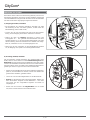
Antenne montieren
Achten Sie bei der Montage des Antennenträgers (Mast oder
Wandausleger) darauf, dass dieser senkrecht steht. Andern-
falls kann die Ausrichtung der Antenne auf den Satelliten zu
Schwierigkeiten führen.
a) Anforderungen an den Antennenträger
Verwenden Sie nur Masten oder Tragrohre, die speziell für
Antennenmontage geeignet sind. Andere Rohre oder Träger
haben zumeist nicht die erforderliche Festigkeit bei Wind- und
Wettereinfl üssen.
• Wählen Sie bei Mastmontage einen Rohrdurchmesser
zwischen 32 bis 60 mm (bei CCA 600x) bzw. zwischen 48 bis
76 mm (bei CCA 750x/CCA 850x) mit einer Wanddicke von
mindestens 2 mm. Bei Wand-montage empfi ehlt CityCom
die Verwendung der Kathrein-Wandhalterungen ZAS 60 oder
ZAS 61.
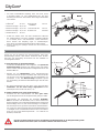
• Bei einer Mastmontage auf dem Dach, muss der Mast über
mindestens 1/6 der freien Länge eingespannt werden
(im Beispiel unten rechts sind dies 0,7 m).
b) Mehrere Antennen an einem Antennenträger:
• Montieren Sie die Parabolantenne am Mast ganz unten,
um das Biegemoment an der Einspannstelle gering zu halten.
• Überschreiten Sie keinesfalls die maximale Belastbar-
keit für den Mast oder Masthalter, wie in deren technischen
Daten angegeben. Die maximale Belastbarkeit ist ausreichend
berücksichtigt, wenn Sie Ihre Antennenanlage so ausführen,
wie im Beispiel rechts gezeichnet und übliche Haushaltsanten-
nen sowie aus dem Fachhandel bezogene Mastbauteile (Rohr
in Stahlgüte St 52 mit Außendurchmesser 60 mm und Wand-
dicke 2,5 mm an der Masteinspannstelle – z. B. ZSH 59 von
Kathrein) verwenden.
Reflektormitte
Ø 32-(60)76 mm
Bei einer anderen Bauweise müssen Sie Windlast und Biegemoment an der Einspannstelle gemäß
DIN EN 60728-11 errechnen (oder von einem Fachmann errechnen lassen).

4 / 20
CityCom
R
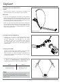
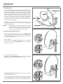
Tragarm
• Stecken Sie den Tragarm in die Öffnung am Refl ektor und
schieben Sie ihn bis zum Anschlag hinein, bis er einrastet.
Mastschelle
• Lockern Sie die Flügelmuttern und bringen Sie den Gewinde-
bügel und die Schließschelle in Montageposition (siehe Grafi k
rechts). Befestigen Sie den Parabolspiegel vorerst locker am
Mast oder dem Ausleger. Später muss der Parabolspiegel noch
in der Azimuth-Richtung ausgerichtet werden.
• Ziehen Sie die Schraubenverbindungen zwischen Mastschel-
le und Antennenträger handfest an (bei CCA 600/x Schlüssel-
weite 10, bei CCA 750/x und 850/x Schlüsselweite 13), ggf.
etwas lockern. Später muss der Parabolspiegel noch in der Ele-
vation ausgerichtet werden.
c) Montage Tragarm und Mastschellen
d) Montage Speisesystemhalterung
• Entfernen Sie die Schelle von der vormontierten Speise-
systemhalterung, lösen Sie die Schraube und setzen
Sie das Speisesystem ein. Schließen Sie die Schel-
le wieder und drehen Sie die Schraube wieder leicht an.
Das Speisesystem muss evtl. noch auf die Polarisation
eingestellt werden. Siehe dazu den Anwendungshinweis des
Speisesystems.
e) Speisesystem (LNB)
Das/die Speisesystem/e sowie Hinweise zu deren Montage
gehören nicht zum Lieferumfang der Parabolantenne.
Bitte entnehmen Sie daher die näheren Informationen zur
sachgerechten Montage den Anleitungen, die dem jeweiligen
Speisesystem beiliegen.
Tipp:
Bei Multifeed-Anwendungen sollte die Antenne auf den
Satelliten ausgerichtet werden, der die pegelschwächeren
Signale sendet.
Beispiel CCA 600
Pos. 1 Pos. 2
ASTRA 19,2° Ost EUTELSAT 13° Ost
EUTELSAT 16° Ost EUTELSAT 10° Ost
EUTELSAT 13° Ost EUTELSAT 7° Ost
• Beispiel für Montagepositionen bei einer Mutifeed-Anwendung
mit bis zu 10° Satellitenabstand in Verbindung mit der
Multifeed-Halterung CCZ 02 (bei CCA 750/850 möglich):

5 / 20
CityCom
R
Antenne ausrichten
Die Antenne muss sowohl von der Richtung (Azimut), als auch von
der Neigung (Elevation) her genau auf den Satelliten ausgerichtet
sein. Bei Multifeed-Lösungen sollte die Antenne auf den Satelliten
mit dem schwächsten Signalpegel ausgerichtet werden.
a) Neigung (Elevation) einstellen
• Bei Einstellung der Neigung (Elevation) beachten Sie bitte
die Skalierung an der, von hinten gesehen, rechten Seite der
Masthalterung (siehe Grafi k rechts).
• Lockern Sie die zwei Schrauben auf jeder Seite der Masthal-
terung, um die Neigung der Antenne verändern zu können.
• Stellen Sie dann die Neigung (Elevation) in Bezug zum
Anzeigepfeil ein – den genauen Elevationswinkel für Ihren
Standort fi nden Sie in der Azimut-/Elevationstabelle am Ende
dieser Anleitung. Wenn Ihr Standort in der Tabelle nicht aufge-
führt ist, orientieren Sie sich am nächstgelegenen Ort.
• Ziehen Sie die vier Schrauben an der Masthalterung handfest
an, die Neigung muss später noch feineingestellt werden.
b) Richtung (Azimut) einstellen
Für die folgenden Schritte benötigen Sie gegebenenfalls einen
Helfer, falls Sie nicht selbst an einem Antennenmessgerät oder
Bildschirm mit angeschlossenem Satelliten-Receiver das Ergeb-
nis der Ausrichtarbeiten beobachten können. Eine exakte Ausrich-
tung der Antenne kann nur mittels eines digitalen Antennenmess-
gerätes geschehen. Fragen Sie hierzu Ihren Fachhändler.
• Stellen Sie am Satelliten-Receiver einen bekannten Programm-
platz ein, um kontrollieren zu können, ob Sie auch wirklich den
gewünschten Satelliten „getroffen“ haben.
• Lösen Sie nun leicht die Flügelmuttern an der Mastschelle.
• Drehen Sie die Antenne grob in Richtung Süden. Drehen Sie
dann die Antenne langsam um die Mittelachse – nach links
und rechts, bis das eingestellte Programm am besten zu
empfangen ist.
• Ziehen Sie im Anschluss die Flügelmuttern erst nur soweit
fest, dass sich die Antenne nicht verdrehen kann.

6 / 20
CityCom
R
d) Antenne endgültig festschrauben
• Ziehen Sie anschließend die Muttern an der Schließschelle
wechselseitig per Hand fest. Im Anschluss ziehen Sie die
Flügelmuttern mit einem Gabelschlüssel (SW 10 bzw. 13 mm)
je um eine Umdrehung nach.
c) Feineinstellung
• Lockern Sie erneut die Schrauben auf jeder Seite der Masthal-
terung und schwenken Sie die Antenne leicht nach oben und
unten, bis Sie entweder am Antennenmessgerät das stärkste
Antennensignal messen oder bei optischer Beurteilung am
Bildschirm den besten Bildeindruck erzielen: Hierzu schwen-
ken Sie die Antenne soweit nach oben und unten, bis Sie
jeweils an die Grenze kommen, wo die ersten sogenannten
„Fischchen“ (analog) oder „Klötzchen“ (digital) am Bildschirm
erscheinen. Stellen Sie die Antenne dann in die Mitte zwischen
diesen beiden Grenzpunkten.
• Korrigieren Sie nun abwechselnd die Richtung (Azimut) und
Neigung (Elevation), bis sich das Mess- oder Bildergebnis
nicht mehr verbessert.
Hinweis: Beim Festdrehen der Muttern an der Schließschelle
kann sich die Antenne leicht verdrehen! Dies sollten
Sie bei der Feineinstellung beachten (und eventuell
für eine ganz genaue Einstellung ausnutzen).
• Bei CCA 600/x:
Ziehen Sie danach links und rechts an der Halterung
die Schrauben an der Neigungsskala fest (Drehmoment-
schlüssel: max. 5 Nm).
• Kontrollieren Sie zum Schluss noch einmal alle Schraubver-
bindungen auf festen Sitz.
• Führen Sie die Kabel in die Öffnung an der Tragarmunterseite
ein und befestigen Sie sie im weiteren Verlauf, damit diese nicht
durch Windbewegungen scheuern und beschädigt werden.
• Bei CCA 750/x und CCA 850/x:
Ziehen Sie danach beide Schrauben an jeder Seite der Mast-
halterung fest (Drehmomentschlüssel: max. 7 Nm).

7 / 20
CityCom
R
Erdungs- und Blitzschutzarbeiten dürfen wegen
der Gefahr unzulänglicher Arbeitsergebnisse nur
von hierfür speziell geschulten Fachkräften des
Elektrohandwerks ausgeführt werden!
Führen Sie niemals Erdungs- und
Blitzschutzarbeiten durch, wenn Sie nicht
selbst Fachkraft mit entsprechenden
Kenntnissen sind!
Die hier abgedruckten Hinweise sind keine
Aufforderung an Nichtfachleute, Erdungs- und
Blitzschutzarbeiten in eigener Verantwortung
durchzuführen, sondern dienen der von Ihnen
beauftragten Fachkraft als zusätzliche Information!
Im schraffi erten Bereich
ist lt. Norm eine
Antennenerdung nicht
zwingend erforderlich.
Antenne erden/Blitzschutz
Die Antenne muss gemäß DIN EN 60728-11 aufgebaut und ent-
sprechend geerdet werden. Von der Erdungspfl icht ausgenommen
sind nur solche Antennen:
– die mehr als 2 m unterhalb der Dachkante
– und zugleich weniger als 1,5 m von Gebäuden
angebracht sind.
Zur Erdung muss der Mast auf kürzestem Weg über einen
geeigneten Erdungsleiter mit der Blitzschutzanlage des Gebäudes
verbunden sein, falls keine Blitzschutzanlage vorhanden ist: mit
der Gebäudeerdung.
Anschlüsse an die Blitzschutzanlage dürfen nur von einem qualifi -
zierten Blitzschutzanlagen-Installateur durchgeführt werden.
a) Geeignet als Erdungsleiter
– ist ein Einzelmassivdraht mit einem Querschnitt von min.
16 mm
2
Kupfer, min. 25 mm
2
Aluminium oder min. 50 mm
2
Stahl.
b) Nicht geeignet als Erdungsleiter
- sind die Außenleiter der Antennenkabel
- metallische Hausinstallationen (z. B. Metallrohre der
Wasser- oder Heizungsanlage) da die Dauerhaftigkeit der
Verbindung nicht gewährleistet werden kann
- oder Schutzleiter oder Neutralleiter des Starkstromnetztes.
c) Führung von Erdungsleitern
• Antennenkabel und Erdungsleiter dürfen nicht durch Räume
geführt werden, die zur Lagerung von leicht entzündlichen
Stoffen dienen (z. B. Heu, Stroh) oder in denen sich eine
explosive Atmosphäre bilden kann (z. B. Gase, Dämpfe).
• Bei Verwendung der Parabolantenne in kompletten Antennen-
anlagen (z. B. Verteilanlagen) müssen zudem die Erdungs-
maßnahmen so ausgeführt sein, dass der Erdungsschutz auch
dann bestehen bleibt, wenn einzelne Einheiten entfernt oder
ausgetauscht werden.
Gefahren können nicht nur durch Gewitter entstehen (Blitzschlag),
sondern auch durch statische Aufl adung oder Kurzschluss in den
angeschlossenen Geräten.
Deshalb muss generell für alle Antennenanlagen aus Sicherheits-
gründen ein Potenzialausgleich aus 4 mm² Kupfer vorgenommen
werden.
Die Kabelschirme aller Koaxialantennen-Niederführungskabel
müssen über einen Potenzialausgleichsleiter mit dem Mast
verbunden werden.

8 / 20
CityCom
R
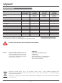
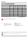
Technische Daten
1)
Bei einem Staudruck von 800 N/m² nach EN 60728-11
2)
90° Elevation sind nur bei einer an der Mastspitze montierten Parabolantenne möglich
Alle Angaben sind typische Werte!
Es können Teile losbrechen, wenn Sie die Grenzlast überschreiten!
Typ
RAL 7011 (Grau)
RAL 9002 (Weiß)
RAL 8012 (Rot)
CCA 600G
CCA 600W
CCA 600R
CCA 750G
CCA 750W
CCA 750R
CCA 850G
CCA 850W
CCA 850R
Bestell-Nr.
200100015
200100014
200100016
200100018
200100017
200100019
200100021
200100020
200100022
Refl ektor Durchmesser mm 570 x 640 740 x 840 850 x 850
Empfangsbereich GHz 10,70-12,75 10,70-12,75 10,70-12,75
Antennengewinn bei 11,75 GHz dBi 35,2 37,8 38,7
Kreuzpolarisationsentkopplung dB > 27 > 27 > 27
Halbwertsbreite ° 2,9 2,2 2,2
Windlast
1)
N 290 495 615
Max. zulässige Windgeschwindigkeit km/h 160 160 160
Grenzlast bei Staudruck 1235 N/m² (160 km/h) N 450 765 950
Spannbereich der Mastschelle mm 32-60 32-76 32-76
Einstellbereich Elevation/Azimut ° 5-50/360 12-45-90
2)
/360 9-41-90
2)
/360
LNB-Aufnahme mm 40 40 40
Verpackungseinheit St. 1 1 1
Gewicht kg 3,36 6,0 6,6
Elektronische Geräte gehören nicht in den Hausmüll, sondern müssen - gemäß Richtlinie 2002/96/EG DES
EUROPÄISCHEN PARLAMENTS UND DES RATES vom 27. Januar 2003 über Elektro- und Elektronik-Altgeräte
fachgerecht entsorgt werden.
Bitte geben Sie dieses Gerät am Ende seiner Verwendung zur Entsorgung an den dafür vorgesehenen öffentlichen
Sammelstellen ab.
ESW GmbH
Elektronik Service Wetzlar GmbH
Philipsstraße 1
D-35576 Wetzlar
Telefon 08641/9545-0 · Fax 08641/9545-36
E-Mail: [email protected]
Internet: www.esw-katek.de
Hinweis: Verehrter Kunde, sollten Sie mit den
CityCom-Qualitätsprodukten wider Erwar-
ten Probleme haben, setzen Sie sich bitte
mit Ihrem Fachhändler bzw. mit unserer
Servicestelle in Verbindung. Die Anschrift
unserer Servicestelle lautet:

9 / 20
CityCom
R

CityCom
R
9364695/-/VKDT/1113/DE - Technische Änderungen vorbehalten!
Internet: www.kathrein.de
KATHREIN-Werke KG • Anton-Kathrein-Straße 1 - 3 • Postfach 10 04 44 • 83004 Rosenheim • Deutschland • Telefon 08031 184-0 • Fax 08031 184-385

CityCom
R
Ein Unternehmen der Kathrein-Firmengruppe
11 / 20
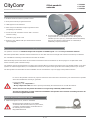
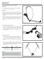
■
Refl
ector made of aluminium, powder coated
■
Rear panel made of pre-galvanised steel
■
LNB support arm of aluminium
■
Mast clamps and threaded clamps of galvanised steel
(completely pre-mounted)
■
Screws and nuts of stainless steel or with a corrosion-
resistant coating
■
Available in grey, white or red
■
Delivery scope: refl
ector with pre-mounted mast and feed
system supports
Features
■
To mount two LNBs (multi-feed reception) on the boom
(only possible for CCA
750/850) to receive the signals of
satellites up to 10° apart (e.g. ASTRA/EUTELSAT HOTBIRD),
the CCZ 02 multi-feed support (Order no. 20010044) is
additionally required (see below).
Proper use (use for the intended purpose)
The parabolic antennas are intended solely for the reception of satellite signals and for use only as domestic antennas.
DIN 4131 specifi es that a domestic antenna should have no more than 6 m free mast length and a fi xed-end moment up to 1650 Nm.
It is unsuitable for mounting on structures that are liable to vibration.
Make absolutely sure that the values for the maximum load listed in the Technical Data (on the last page) are complied with. If this
load is exceeded, parts could break away!
The parabolic atennas are designed for use with a feed system (LNB) for reception of the signals from one satellite position, or two feed
systems for multi-feed applications (CCA 750/850 with CCZ 02) for reception of the signals from two satellite positions up to 10°apart.
The feed systems and instructions for their installation are not included in the scope of supply of the parabolic antenna.
Optionally available accessories
■
Multi-feed support CCZ 02, Order no. 20010044
Multi-feed support suitable for CCA
750/850.
To determine the elevation values for your location,
consult the azimuth/elevation calculation table on
the following Internet website:
http://www.kathrein.de
Offset parabolic
antennas
CCA 600/x
CCA 750/x
CCA 850/x
Do not use the parabolic antenna for purposes other than those listed in this manual! Any use other than that specifi ed
above will invalidate the warranty or guarantee.
In particular, never
• modify any of its components or
• fi t any components other than those expressly intended by the manufacturer for use with the antenna.
Breach of these rules may lead to the antenna no longer being suffi ciently stable and safe!
The laws and standards currently valid for the installation and operation of the antenna are binding and are to be
observed an applied without fail!

12 / 20
CityCom
R
• Under no circumstances install antennas in the vicinity of overhead power cables; otherwise the required clearances,
which are absolutely essential, may no longer be satisfi ed. Maintain a clearance of at least 1 m from all other electrical
equipment in all directions!
If you or metal parts of the antenna touch any electrical device there is a serious risk of a fatal electric shock!
• Never work on antenna systems during a thunderstorm or when a thunderstorm is approaching.
There is a risk of a fatal electric shock!
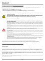
Basic Safety Precautions
• Never install antennas on buildings with easily fl ammable roof coverings such as straw, rushes or similar materials!
Otherwise there is a risk of fi re due to atmospheric over-voltages (static charges) or lightning discharges
(e.g. during thunderstorms).
• The installation operations described here assume good craftsmanship capabilities and knowledge of the behaviour of
materials under the effects of wind. Therefore if you do not possess the required skills, have this work performed by a
specialist.
• The person doing the work must wear strong non-slip footwear, must not be liable to dizziness, must be able to move
around safely on the roof and have a secure standing and attachment position (if necessary, wear a safety harness when
on the roof).
• Make sure that the roof is able to bear your weight. Never walk on fragile or unstable surfaces! In case of doubt, contact
a qualifi ed specialist dealer or specialist roofi ng contractor to fi nd an appropriate installation location.
• Do not go on to roofs or other high places without a correctly attached safety harness that is in good condition. Otherwise
use a work platform.
• Ladders or other means of climbing must be in faultless condition (dry, clean and non-slip). Never build any irresponsible
“scrambling towers”!
• If there is a risk that passers-by may be injured by items falling from above during installation, you must close off the risk
area using barriers! Make sure that no-one is underneath the installation location.
Risk of death or injury due to falling from the roof, falling through the roof and falling parts, plus the possibility
of damage to the roof.
• The respective national safety regulations and current standards such as DIN EN 60728-11 should be complied with.
• Any other use or failure to comply with these instructions will result in voiding of warranty coverage.
Before you install, connect or use the parabolic antenna, make sure that you comply with the instructions in this manual!
If you disregard these instructions,
• malfunctions may arise, creating risks to your life and health,
• defects in the installation or the connection may cause damage to the antenna or to the attachment point,
• the manufacturer will not accept liability for malfunctions and damage arising!
When working on antenna systems, please remember your duty of care towards your fellow human beings!
Keep the manual for any questions that arise later, and if the building passes to another owner, pass it on to the new owner!
Selecting the installation site
It is essential to select the correct installation site. This determines whether your parabolic antenna can be erected safely and perform to its
optimum capabilities.
When selecting the installation site, take account of special features of the structure of the building. If the installation is at the edge of the roof
or the building or on a cylindrical structure, DIN 1055, parts 4 and 4131 specifi es the increased wind and vibration loadings that should be
allowed for. The dynamic properties of the antenna and the structure can mutually infl uence each other and cause detrimental changes.
Disregarding these considerations can lead to the maximum load or vibration fatigue stress listed in the Technical Data being exceeded.
The parabolic antenna need not necessarily be mounted on the roof, since the requirement is not height as such but an unobstructed
“view” of the satellite. For this reason, an appropriate installation site might also be found for instance in the garden, on the terrace, on the
face of the building or on a garage.
In fact if other sites are possible, it is better to avoid the roof. This will result in less work for you and will reduce the hazards associated
with installation work on the roof!

13 / 20
CityCom
R
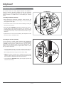
1 TÜRKSAT
*)
42° East
2 ASTRA 2 group 28.2° East
3 ASTRA 3 group 23.5° East
4 ASTRA 1 group 19.2° East
5 EUTELSAT W 2 16° East
• Do make sure that there are no obstacles between the
parabolic antenna and the respective satellite (such as trees,
roofs, house eaves or other antennas). Such items can
impair reception to the extent that during unfavourable stormy
weather the signal is lEast altogether.
*)
The reception is dependent upon the respective location and the satel-
lite coverage zone
6 EUTELSAT
HOTBIRD
13° East
7 EUTELSAT W 1 10° East
8 HISPA-Sat 30° West
• For good reception, an unobstructed “view” to the south
(+/- 20°) must be ensured, at an elevation of about 30°. The
following satellites are then available for selection:
Installing the antenna
When installing the antenna carrier (mast or wall boom), ensure
that it is standing upright. Otherwise, there may be problems with
the alignment of the antenna to the satellites.
a) Requirements on the antenna carrier
Use only masts or support tubes that are specially designed
for installation of antennas. Other tubes generally do not
have the strength required to withstand the forces of wind and
weather.
• For mast installation, select a tube diameter between 32 and
60 mm (for CCA 600x) or between 48 and 76 mm (for CCA 750x/
CCA 850x) with a wall thickness of at least 2 mm. For wall
installation, CityCom recommends the use of Kathrein’s
ZAS 60 or ZAS 61 wall brackets.
• For mast installation on a roof, the mast must be clamped for
at least 1/6 of its free length (in the example bottom right this
is 0.7 m).
b) Several antennas on a single antenna carrier:
• Install the parabolic antenna as far down the mast as
possible, so as to minimise the bending moment at the
clamping point.
• Under no circumstances exceed the maximum value for
the loading on the mast or mast support, as stated in the
Technical Data. Suffi cient cognizance of the maximum
loading is achieved if you arrange your antenna system as
shown in example bottom right and use conventional domestic
antennas together with mast components from a specialist
supplier (tube in steel grade St 52 with outer diameter 60 mm
and wall thickness 2.5 mm at the mast clamping point –
e.g. ZSH 59 from Kathrein).
Ø 32-(60)76 mm
If you arrange the structure differently you must calculate wind loading and bending moment at the
clamping point as specifi ed in DIN EN 60728-11 (or have a specialist do the calculation for you).
East
South
West
Reflektormitte
Centre of the
refl ector
3.5 m
3.0 m
2.0 m
min. 0.7 m

14 / 20
CityCom
R
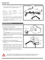
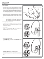
Support arm
• Insert the support arm into the opening on the refl ector and slide it in
as far as it will go until it locks into place.
Mast clamp
• Slacken the winged nuts and bring the threaded U-bolt and
threaded clamp into installation position (see graphic on right).
Attach the parabolic refl ector to the mast or boom, at fi rst
loosely. Later on, the parabolic refl ector’s azimuth will have to
be aligned.
• Tighten the screw connectors between mast clamp and
antenna support fi nger-tight (for CCA 600/x spanner size 10,
for CCA 750/x and 850/x spanner size 13), loosen if required.
Later on, the parabolic refl ector’s elevation will have to be
aligned.
c) Installing the support arm and mast clamps
d) Installation feed system support
• Remove the clamp from the pre-feed system support, loosen
the screw and insert the feed system. Close the clamp and
tighten the screw slightly. The feed system may need to be still
set to the polarisation. Please refer to the application note of
the feed system.
e) Feed system (LNB)
The feed system(s) and instructions for their installation are
not included in the scope of supply of the parabolic anten-
na. For more detailed information on their correct installation
please refer to the manuals supplied with the respective feed
system.
Tip:
For multi-feed applications the antenna should be aligned
towards the satellite which is transmitting the weakest signal
level.
Example CCA 600
Pos. 1 Pos. 2
ASTRA 19,2° East EUTELSAT 13° East
EUTELSAT 16° East EUTELSAT 10° East
EUTELSAT 13° East EUTELSAT 7° East
• Example for the installation positions for a multi-feed applica-
tion with up to 10° satellite spacing using the multi-feed
support CCZ 02 (possible with CCA 750/850):

15 / 20
CityCom
R
Aligning the antenna
The antenna must be exactly aligned towards the satellite in
respect of both the direction (azimuth) and also the inclination
(elevation). For multi-feed applications the antenna should be
aligned towards the satellite which is transmitting the weakest
signal.
a) Setting inclination (elevation)
• When adjusting the inclination (elevation), please observe the
scaling on the right side of the mast fi xing, as seen from behind
(see graphic on the right).
• Loosen both screws on each side of the mast fi xing to modify the
elevation of the antenna.
• Now adjust the inclination (elevation) respective the arrow –
you will fi nd the exact elevation angle for your location in the
azimuth/elevation table at the end of this manual. If your location
is not listed in this table, use the nearest listed location as your
reference.
• Tighten the four screws on the mast fi xing, fi ne adjustment of the
elevation must be undertaken later.
b) Setting the direction (azimuth)
If you yourself are unable whilst performing the adjustments
to read the results of the alignment work on an antenna meter
or screen connected to the satellite receiver, you may need an
assistant for the following steps. The precise alignment of the
antenna can be achieved only if a digital antenna meter is used.
Ask your dealer about this.
• Set the satellite receiver to a known channel so that you can
verify that you have really “locked on” to the desired satellite.
• Now slightly loosen the wing nuts on the mast clamp.
• Twist the antenna so that it faces roughly south. Then slowly
twist the antenna about its central axis to left and right until the
best reception is obtained for the selected channel.
• Then tighten the wing nuts initially just enough to prevent the
antenna from turning.

16 / 20
CityCom
R
Zenith
Elevation angle
West
Azimuth angle
East
South
Horizon
d) Final tightening of the antenna
• Tighten the nuts on the bracket using your hand. Subsequently
tighten the wing nuts using an open-ended spanner (AF 10 or
13 mm) by one turn each.
c) Fine adjustment
• Loosen the screws on each side of the mast fi xing and swivel
the antenna slightly upwards and downwards, until you either
measure the strongest antenna signal on your antenna meter
or until you visualize the best image quality on your screen: to
do this, swivel the antenna upwards and then downwards until
you come to the points where the so-called “fi sh” (analogue)
or “blocks” (digital) appear on your screen. Adjust the antenna
between these two limits.
• Alternate correcting the orientation (azimuth) and inclination
(elevation) until the measurement or image results no longer
improve.
Note: There is a risk of the antenna twisting when the nuts
are being tightened on the clamp! You should bear
this in mind while performing fi ne adjustment (and
take advantage of this for a precise adjustment).
• For CCA 600/x:
Tighten the screws left and right of the bracket on the
inclination scale (torque spanner: max. 5 Nm).
• At the end, make sure all screw fi xings are tight.
• Insert the cables in the opening on the bottom of the boom and
fasten these so that they do not chafe and are not damaged by
wind.
• For CCA 750/x and CCA 850/x:
Tighten both screws on each side of the mast fi xing (torque
spanner : max. 7 Nm).

17 / 20
CityCom
R
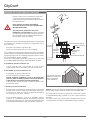
The standard says that
within the hatched area
antenna grounding
is not compulsory.
Antenna grounding/lightning protection
Grounding
conductor
Grounding
connection
Equipotential bonding rail
Equipotential
bonding
cable
Equipotential bonding rail
Mains connection
Equipoten-
tial bond-
ing cable
Because of the serious consequences if the work
is not done properly, grounding and lightning
protection work may be performed only by specially
trained electricians!
Never perform grounding and lightning
protection work if you are not a specialist with
the appropriate skills!
The instructions printed here are not an
invitation to non-specialists to perform grounding
and lightning protection work on their own account;
they are meant solely as additional information for
the specialists whom you employ!
The antenna must be erected to DIN EN 60728-11 and grounded
as specifi ed. The grounding requirement is inapplicable only to
those antennas:
– more than 2 m below the edge of the roof
– and at the same time less than 1.5 m from buildings.
For grounding, the mast must be connected by means of a suitable
ground conductor to the lightning protection system of the building,
using the shortest route. If no lightning protection system is availa-
ble: to the building‘s ground conductor.
Connection to the lightning protection system may be made only
by a qualifi ed lightning protection system installation engineer.
a) Suitable as ground conductors are:
– a single solid wire with a cross-section of at least 16 mm²
copper, at least 25 mm² aluminium or at least 50 mm² steel.
b) Unsuitable as ground conductors are:
- b) Unsuitable as ground conductors are:
- the outer conductors of antenna cables
- metallic domestic installations (such as the metal pipe-
work of a water or heating system), since the permanence
of the electrical connection cannot be guaranteed
- or the protective ground conductor or neutral conductor of the
mains power supply
c) Routing of ground conductors
• Antenna cables and grounding conductors must not be routed
through rooms used for storing easily fl ammable substances
(such as hay or straw) or in which an explosive atmosphere
can develop (such as gases, vapours).
• If the parabolic antenna is used in an integrated antenna
system (e. g. a distribution system), the grounding measures
must also be designed in such a way that grounding protection
is still maintained if individual units are removed or replaced.
Hazards may be caused not only by thunderstorms (lightning), but
also by static charges and short circuits in the connected units.
For safety reasons therefore in general for all antenna systems
an equipotential bonding conductor of 4 mm² copper should be
provided.
The cable screens of all coaxial antenna downlink cables must be
connected to the mast with an equipotential bonding conductor.

18 / 20
CityCom
R
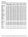
Technical Data
1)
At a dynamic pressure of 800 N/m² to EN 60728-11
2)
90° elevation is only possible for a parabolic antenna that is mounted on the tip of a mast
All fi gures are typical values!
If the maximum load is exceeded, parts may break away!
Type
RAL 7011 (Grey)
RAL 9002 (White)
RAL 8012 (Red)
CCA 600G
CCA 600W
CCA 600R
CCA 750G
CCA 750W
CCA 750R
CCA 850G
CCA 850W
CCA 850R
Order no.
200100015
200100014
200100016
200100018
200100017
200100019
200100021
200100020
200100022
Refl ector diameter mm 570 x 640 740 x 840 850 x 850
Reception range GHz 10.70-12.75 10.70-12.75 10.70-12.75
Antenna gain at 11.75 GHz dBi 35.2 37.8 38.7
Cross-polarisation decoupling dB > 27 > 27 > 27
Half-power beam width ° 2.9 2.2 2.2
Wind load
1)
N 290 495 615
Max. allowable wind speed km/h 160 160 160
Maximum load at a dynamic pressure of
1235 N/m² (160 km/h)
N 450 765 950
Mast clamp range mm 32-60 32-76 32-76
Setting range Elevation/Azimuth ° 5-50/360 12-45-90
2)
/360 9-41-90
2)
/360
LNB support mm 40 40 40
Packing unit Pc. 1 1 1
Weight kg 3.36 6.0 6.6
Electronic equipment is not household waste in accordance with directive 2002/96/EC OF THE EUROPEAN PARLIA-
MENT AND THE COUNCIL dated 27
th
January 2003 on used electrical and electronic equipment, it must be disposed of
properly.
At the end of its service life, take this unit for disposal to an appropriate offi cial collection point.
ESW GmbH
Elektronik Service Wetzlar GmbH
Philipsstraße 1
35576 Wetzlar/GERMANY
Phone +49 8641/9545-0 · Fax + 49 8641/9545 36
E-mail: [email protected]
Internet: www.esw-katek.de
Note: Dear customer,
Should you experience unexpected dif-
fi culties with CityCom’s quality products,
please contact your specialist dealer or
our service centre. The address of our
service centre is:

19 / 20
CityCom
R

CityCom
R
9364695/-/VKDF/1113/EN - Technical data subject to change!
Internet: www.kathrein.de
KATHREIN-Werke KG • Anton-Kathrein-Straße 1 - 3 • P.O. Box 10 04 44 • 83004 Rosenheim • GERMANY• Phone +49 8031 184-0 • Fax +49 8031 184-385
-
 1
1
-
 2
2
-
 3
3
-
 4
4
-
 5
5
-
 6
6
-
 7
7
-
 8
8
-
 9
9
-
 10
10
-
 11
11
-
 12
12
-
 13
13
-
 14
14
-
 15
15
-
 16
16
-
 17
17
-
 18
18
-
 19
19
-
 20
20


in anderen Sprachen
- English: CityCom CCA 750G User manual
Andere Dokumente
-
Kathrein Euroline KEA 650 Benutzerhandbuch
-
Kathrein 20010006 Benutzerhandbuch
-
-
Kathrein CAS 80ws Datenblatt
-
Kathrein CAS 90ws Benutzerhandbuch
-
-
-
-
-