Seite wird geladen ...

Motoriduttori per scorrevoli
Gear-motor for sliding gates
Motoreducteur pour coulissants
Motorreductores para rejas correderas
Getriebe für Schiebegitter
Motorredutores para portões de correr
Napęd silnikowy do bram przesuwnych
TURBO 30
Istruzioni ed avvertenze per l’installazione e l’uso
Instructions and warnings for installation and use
Instrucciones y advertencias para su instalación y uso
Anleitungen und Hinweise zu Installation und Einsatz
Instruções e advertências para a instalação e utilização
Instructions et avertissements pour l’installation et l’usage
Management
System
ISO 9001:2008
www.tuv.com
ID 9105043769

2
IT
1
2
3
4
5
6
7
Avvertenze per la sicurezza
2.1
2.2
4.1
4.2
4.3
4.4
4.5
5.1
5.2
Introduzione al prodotto
Descrizione del prodotto
Quadro d’insieme e caratteristiche tecniche
Veriche preliminari
Installazione del prodotto
Funzionamento manuale
Installazione
Fissaggio
Fissaggio cremagliera
Fissaggio necorsa
Collaudo e messa in servizio
Collaudo
Messa in servizio
Istruzioni ed avvertenze destinate
all’utilizzatore nale
Dichiarazione CE di conformità
pag. 3
pag. 4
pag. 4
pag. 4
pag. 5
pag. 5
pag. 5
pag. 5
pag. 6
pag. 6
pag. 7
pag. 7
pag. 7
pag. 7
pag. 8
pag. 59
INDICE

3
IT
1 - AVVERTENZE PER LA SICUREZZA
ATTENZIONE – per la sicurezza delle persone è im-
portante rispettare queste istruzioni e conservarle
per utilizzi futuri.
Leggere attentamente le istruzioni prima di eseguire l’installazione.
La progettazione e la fabbricazione dei dispositivi che
compongono il prodotto e le informazioni contenute
nel presente manuale rispettano le normative vigenti
sulla sicurezza. Ciò nonostante un’installazione e una
programmazione errata possono causare gravi ferite
alle persone che eseguono il lavoro e a quelle che
useranno l’impianto. Per questo motivo, durante l’in-
stallazione, è importante seguire attentamente tutte le
istruzioni riportate in questo manuale.
Non procedere con l’installazione se si hanno dubbi di qualunque
natura e richiedere eventuali chiarimenti al Servizio Assistenza Key
Automation.
Per la legislazione Europea la realizzazione di una
porta automatica o un cancello automatico deve ri-
spettare le norme previste dalla Direttiva 2006/42/
CE (Direttiva Macchine) e in particolare, le norme EN
12445; EN 12453; EN 12635 e EN 13241-1, che con-
sentono di dichiarare la conformità dell’automazione.
In considerazione di ciò, il collegamento denitivo dell’automatismo
alla rete elettrica, il collaudo dell’impianto, la sua messa in servizio
e la manutenzione periodica devono essere eseguiti da personale
qualicato ed esperto, rispettando le istruzioni riportate nel riquadro
“Collaudo e messa in servizio dell’automazione”.
Inoltre, egli dovrà farsi carico di stabilire anche le prove previste in
funzione dei rischi presenti e dovrà vericare il rispetto di quanto
previsto da leggi, normative e regolamenti: in particolare, il rispetto
di tutti i requisiti della norma EN 12445 che stabilisce i metodi di
prova per la verica degli automatismi per porte e cancelli.
ATTENZIONE - Prima di iniziare l’installazione, effet-
tuare le seguenti analisi e veriche:
vericare che i singoli dispositivi destinati all’automazione siano
adatti all’impianto da realizzare. Al riguardo, controllare con partico-
lare attenzione i dati riportati nel capitolo “Caratteristiche tecniche”.
Non effettuare l’installazione se anche uno solo di questi dispositivi
non è adatto all’uso;
vericare se i dispositivi acquistati sono sufcienti a garantire la si-
curezza dell’impianto e la sua funzionalità;
eseguire l’analisi dei rischi che deve comprendere anche l’elenco
dei requisiti essenziali di sicurezza riportati nell’ Allegato I della Di-
rettiva Macchine, indicando le soluzioni adottate. L’analisi dei rischi
è uno dei documenti che costituiscono il fascicolo tecnico dell’au-
tomazione. Questo dev’essere compilato da un installatore profes-
sionista.
Considerando le situazioni di rischio che possono
vericarsi durante le fasi di installazione e di uso del
prodotto è necessario installare l’automazione osser-
vando le seguenti avvertenze:
non eseguire modiche su nessuna parte dell’automatismo se non
quelle previste nel presente manuale. Operazioni di questo tipo
possono solo causare malfunzionamenti. Il costruttore declina ogni
responsabilità per danni derivanti da prodotti modicati arbitraria-
mente;
evitare che le parti dei componenti dell’automazione possano venire
immerse in acqua o in altre sostanze liquide. Durante l’installazio-
ne evitare che i liquidi possano penetrare all’interno dei dispositivi
presenti;
se sostanze liquide penetrano all’interno delle parti dei componenti
dell’automazione, scollegare immediatamente l’alimentazione elet-
trica e rivolgersi al Servizio Assistenza Key Automation. L’utilizzo
dell’automazione in tali condizioni può causare situazioni di pericolo;
non mettere i vari componenti dell’automazione vicino a fonti di ca-
lore né esporli a amme libere. Tali azioni possono danneggiarli ed
essere causa di malfunzionamenti, incendio o situazioni di pericolo;
tutte le operazioni che richiedono l’apertura del guscio di protezio-
ne dei vari componenti dell’automazione, devono avvenire con la
centrale scollegata dall’alimentazione elettrica. Se il dispositivo di
sconnessione non è a vista, apporre un cartello con la seguente
dicitura: “MANUTENZIONE IN CORSO”;
tutti i dispositivi devono essere collegati ad una linea di alimentazio-
ne elettrica dotata di messa a terra di sicurezza;
il prodotto non può essere considerato un efcace sistema di prote-
zione contro l’intrusione. Se desiderate proteggervi efcacemente,
è necessario integrare l’automazione con altri dispositivi;
il prodotto può essere utilizzato esclusivamente dopo che è stata
effettuata la “messa in servizio” dell’automazione, come previsto nel
paragrafo “Collaudo e messa in servizio dell’automazione”;
prevedere nella rete di alimentazione dell’impianto un dispositivo di
disconnessione con una distanza di apertura dei contatti che con-
senta la disconnessione completa nelle condizioni dettate dalla ca-
tegoria di sovratensione III;
per la connessione di tubi rigidi e essibili o passacavi utilizzare
raccordi conformi al grado di protezione IP55 o superiore;
l’impianto elettrico a monte dell’automazione deve rispondere alle
vigenti normative ed essere eseguito a regola d’arte;
si consiglia di utilizzare un pulsante di emergenza da installare nei
pressi dell’automazione (collegato all’ingresso STOP della scheda
di comando) in modo che sia possibile l’arresto immediato in caso
di pericolo;
questo dispositivo non è destinato a essere usato da persone (bam-
bini compresi) le cui capacità siche, sensoriali o mentali siano ri-
dotte, oppure con mancanza di esperienza o di conoscenza, a meno
che esse abbiano potuto beneciare, attraverso l’intermediazione di
una persona responsabile della loro sicurezza, di una sorveglianza
o di istruzioni riguardanti l’uso del dispositivo;
i bambini devono essere sorvegliati per sincerarsi che non giochino
con l’apparecchio.
ATTENZIONE - Il materiale dell’imballaggio di tutti i
componenti dell’automazione deve essere smaltito
nel pieno rispetto della normativa presente a livello
locale.
ATTENZIONE - I dati e le informazioni indicate in que-
sto manuale sono da ritenersi suscettibili di modica
in qualsiasi momento e senza obbligo di preavviso da
parte di Key Automation S.r.l.

4
IT
2.1 - Descrizione del prodotto
2 - INTRODUZIONE AL PRODOTTO
DATI TECNICI TURBO 30
Modello SC-30CSM
Centrale CT-24M
Alimentazione 230 (24) Vac (Vdc)
Potenza assorbita 250 W
Assorbimento motore 1,1 A
Grado di protezione IP 54
Coppia Nm 10
Velocità* 20 cm/s
Forza di spinta 300 N
Peso massimo cancello 300 Kg
Classe di isolamento 1
Ciclo di lavoro 50 %
Temperatura di esercizio -20 +55 °C
Peso 10,5 Kg
2.2 - Quadro d’insieme e caratteristiche tecniche
Motoriduttore elettromeccanico irreversibile per cancelli scorrevoli
dal peso max di 300 Kg. Alimentazione a 230 Vac (motore a 24Vdc),
frizione elettronica, encoder, centrale e radio incorporate, completo
di necorsa magnetici, piastra di ssaggio e viti di ssaggio.
Pignone M4. Predisposto per inserimento delle batterie tampone.
* Valore variabile in relazione al peso del cancello
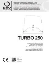
INSTALLAZIONE STANDARD
1 Colonnina con fotocellula
2 Automazione motoriduttore
3 Fotocellula di rilevazione
4 Lampeggiante di segnalazione
5 Selettore a chiave
6 Trasmettitore radio
253
240
81
170,5
1 1
2
3
4
5
6
3

5
IT
IT
4 - INSTALLAZIONE DEL PRODOTTO
4.1 - Funzionamento manuale
4.2 - Installazione
3 - VERIFICHE PRELIMINARI
Prima di installare il prodotto vericare e controllare i seguenti punti:
la struttura del cancello deve essere solida ed appropriata;
durante la corsa, il cancello non deve presentare eccessivi sbanda-
menti laterali;
il sistema di ruote/rotaia inferiore e rulli/guida superiore deve funzio-
nare senza eccessivi attriti
per evitare il deragliamento del cancello devono essere installate le
battute di arresto dello scorrevole, sia in apertura che in chiusura, e
un secondo rullo/guida superiore nel pieno rispetto della normativa
vigente;
nei cancelli preesistenti eliminare l’eventuale serratura manuale;
portare alla base del cancello le canaline di adduzione dei cavi di
alimentazione (Ø25-50mm) e di collegamento esterno (fotocellula,
lampeggiante, selettore a chiave, ecc.).
Per sbloccare il motoriduttore, alzare lo sportellino e inserire la chia-
ve quindi ruotarla in senso antiorario di 350°.
Quando si vuole riarmare il sistema, fare attenzione a ruotare com-
Rispettando le misure d’ingombro, ssare a terra la piastra di base
mediante 4 robusti tasselli ad espansione (g.3) oppure annegarla
Attenzione : Posizionare i due bulloni (A) in dotazione, nelle apposite forature quadrate al di sotto della piastra.
N.B. É necessario conoscere le dimensioni della cremagliera per poter calcolare con precisione il posizionamento della contropiastra.
pletamente la chiave in senso orario.
Accertarsi che il motore non sia in funzione e l’anta sia ferma.
Porre la chiave in un luogo sicuro e facilmente ricordabile.
nel calcestruzzo (g.4).
Prevedere una o più guaine per il passaggio dei cavi elettrici.
Fig. 2
Fig. 3 Fig. 4

6
IT
4.4 - Fissaggio cremagliera
Fig. 9
4.3 - Fissaggio
Fig. 5 Fig. 6 Fig. 7
BATTERIE TAMPONE
Turbo 30 è provvisto di una sede per poter installare due batterie
tampone
TIPO: 12V 1,2Ah DIM : 44 x 98 x 52
Devono essere collegate con il carica batterie modello:
900CABAT-30
85mm
85mm
10mm
1mm
Togliere il coperchio svitando le viti (g.5).
Appoggiare il motoriduttore sulla piastra posizionarlo come indicato
in g.8.
Avvitare i dadi alle due viti (g.6).
É importante bloccare energicamente i due dadi M12, assicuran-
dosi che durante tutta la corsa del cancello, il motoriduttore sia ben
saldo a terra.
Sbloccare il motoriduttore nel modo indicato in g.2 e portare il can-
cello in completa apertura.
Appoggiare un elemento di cremagliera al pignone, e ssare lo stes-
so con viti e distanziali al cancello.
Spostare manualmente il cancello portando il pignone in corrispon-
denza dell’ultimo distanziale.
Fissare l’elemento di cremagliera denitivamente.
Qualora la regolazione consentita dalla cremagliera non fosse suf-
ciente, è possibile compensare l’altezza del motoriduttore agendo
sulle quattro viti (g.7).
Si consiglia, dopo alcune manovre del motore, un ulteriore ssaggio
delle viti.
Per un corretto posizionamento degli altri elementi e garantire la
loro rettilineità, è necessario utilizzare un elemento di cremagliera
usandolo come appoggio e riferimento (g.9).
Bisogna garantire inoltre un’aria fra cremagliera e pignone di 2 mm
così da non far gravare il peso del cancello sul pignone del motori-
duttore (g.8).

7
IT
4.5 - Fissaggio necorsa
Fig. 10
Fig. 11
s
Il cancello deve essere dotato di fermi di arresto in apertura e in
chiusura che impediscano il deragliamento del cancello stesso.
La posizione del fermo d’arresto deve garantire che le staffe di ne-
corsa non entrino in collisione con il pignone.
Nel caso in cui i necorsa non fossero rilevati dalla centrale si consi-
glia di ruotare entrambi i magneti di 180° sull’asse orizzontale della
staffetta metallica portamagnete.
Posizionare le staffe di ne corsa in modo che il punto indicato (S)
in g.10 sia al centro del pignone.
La distanza da tenere tra magnete e motore deve essere tra i 5 e
10 mm.
Fissare la staffa del necorsa mediante i grani (g.11)
5 - COLLAUDO E MESSA IN SERVIZIO
5.2 - Messa in servizio
A seguito del positivo collaudo di tutti (e non solo di alcuni) i disposi-
tivi dell’impianto si può procedere con la messa in servizio;
è necessario realizzare e conservare per 10 anni il fascicolo tecnico
dell’impianto che dovrà contenere lo schema elettrico, il disegno o
foto dell’impianto, l’analisi dei rischi e le soluzioni adottate, la dichia-
razione di conformità del fabbricante di tutti i dispositivi collegati,
il manuale istruzioni di ogni dispositivo e il piano di manutenzione
dell’impianto;
ssare sul cancello o la porta una targa indicante i dati dell’automa-
zione, il nome del responsabile della messa in servizio, il numero di
matricola e l’anno di costruzione, il marchio CE;
ssare una targa che indichi le operazioni necessarie per sbloccare
manualmente l’impianto;
realizzare e consegnare all’utilizzatore nale la dichiarazione di
conformità , le istruzioni e avvertenze d’uso per l’utilizzatore nale e
il piano di manutenzione dell’impianto;
accertarsi che l’utilizzatore abbia compreso il corretto funzionamen-
to automatico, manuale e di emergenza dell’automazione;
informare anche in forma scritta l’utilizzatore nale sui pericoli e ri-
schi ancora presenti;
ATTENZIONE - dopo la rilevazione di un ostacolo, il cancello o la
porta si ferma in apertura e viene esclusa la chiusura automatica;
per riprendere il movimento bisogna premere il pulsante di coman-
do o usare il trasmettitore.
5.1 - Collaudo
Tutti i componenti dell’impianto devono essere collaudati seguendo
le procedure indicate nei rispettivi manuali di istruzioni;
controllare che siano rispettate le indicazioni del Capitolo 1 – Avver-
tenze per la sicurezza;
controllare che il cancello o la porta si possano muovere liberamen-
te una volta sbloccata l’automazione e che siano in equilibrio e ri-
mangano quindi fermi se lasciati in qualsiasi posizione;
controllare il corretto funzionamento di tutti i dispositivi collegati (fo-
tocellule, bordi sensibili, pulsanti di emergenza, altro) effettuando
delle prove di apertura, chiusura e arresto del cancello o della porta
tramite i dispositivi di comando collegati (trasmettitori, pulsanti, se-
lettori);
effettuare le misurazioni della forza d’impatto come previsto dalla
normativa EN12445 regolando le funzioni di velocità, forza motore e
rallentamenti della centrale nel caso in cui le misurazioni non diano i
risultati desiderati no a trovare il giusto settaggio.
Il collaudo dell impianto va eseguito da un tecnico qualicato che
deve effettuare le prove richieste dalla normativa di riferimento in
funzione dei rischi presenti, vericando il rispetto di quanto previsto
dalle normative, in particolare la norma EN12445 che indica i meto-
di di prova per gli automatismi per porte e cancelli.

8
IT
Key Automation S.r.l. produce sistemi per l’automazione di cancelli,
porte garage, porte automatiche, serrande, barriere per parcheg-
gi e stradali. Key Automation non è però il produttore della vostra
automazione, che è invece il risultato di un’opera di analisi, valu-
tazione, scelta dei materiali, e realizzazione dell’impianto eseguita
dal vostro installatore di ducia. Ogni automazione è unica e solo il
vostro installatore possiede l’esperienza e la professionalità neces-
sarie ad eseguire un impianto secondo le vostre esigenze, sicuro ed
afdabile nel tempo, e soprattutto a regola d’arte, rispondente cioè
alle normative in vigore. Anche se l’automazione in vostro possesso
soddisfa il livello di sicurezza richiesto dalle normative, questo non
esclude l’esistenza di un “rischio residuo”, cioè la possibilità che si
possano generare situazioni di pericolo, solitamente dovute ad un
utilizzo incosciente o addirittura errato, per questo motivo desideria-
mo darvi alcuni consigli sui comportamenti da seguire:
• prima di usare per la prima volta l’automazione, fatevi spiegare
dall’installatore l’origine dei rischi residui;
• conservate il manuale per ogni dubbio futuro e consegnatelo ad un
eventuale nuovo proprietario dell’automazione;
• un uso incosciente ed improprio dell’automazione può farla diven-
tare pericolosa: non comandate il movimento dell’automazione se
nel suo raggio di azione si trovano persone, animali o cose;
• se adeguatamente progettato un impianto di automazione garanti-
sce un alto grado di sicurezza, impedendo con i suoi sistemi di rile-
vazione il movimento in presenza di persone o cose, e garantendo
un’attivazione sempre prevedibile e sicura. È comunque prudente
vietare ai bambini di giocare in prossimità dell’automazione e per
evitare attivazioni involontarie non lasciare i telecomandi alla loro
portata.
• non appena notate qualunque comportamento anomalo da par-
te dell’automazione, togliete alimentazione elettrica all’impianto ed
eseguite lo sblocco manuale. Non tentate da soli alcuna riparazio-
ne, ma richiedete l’intervento del vostro installatore di ducia: nel
frattempo l’impianto può funzionare come un’apertura non automa-
tizzata, una volta sbloccato il motoriduttore con apposita chiave di
sblocco data in dotazione con l’impianto. Con le sicurezze fuori uso
è necessario far riparare quanto prima l’automatismo;
• in caso di rotture o assenza di alimentazione: attendete l’intervento
del vostro installatore, o il ritorno dell’energia elettrica se l’impianto
non è dotato di batterie tampone, l’automazione può essere aziona-
ta come una qualunque apertura non automatizzata. Per fare ciò è
necessario eseguire lo sblocco manuale;
• sblocco e movimento manuale: prima di eseguire questa opera-
zione porre attenzione che lo sblocco può avvenire solo quando
l’anta è ferma.
• Manutenzione: Come ogni macchinario la vostra automazione
ha bisogno di una manutenzione periodica afnché possa funzio-
nare più a lungo possibile ed in completa sicurezza. Concordate
con il vostro installatore un piano di manutenzione con frequenza
periodica; Key Automation consiglia un intervento ogni 6 mesi per
un normale utilizzo domestico, ma questo periodo può variare in
funzione dell’intensità d’uso. Qualunque intervento di controllo, ma-
nutenzione o riparazione deve essere eseguito solo da personale
qualicato.
• Non modicate l’impianto ed i parametri di programmazione e di
regolazione dell’automazione: la responsabilità è del vostro instal-
latore.
• Il collaudo, le manutenzioni periodiche e le eventuali riparazioni
devono essere documentate da chi le esegue e i documenti conser-
vati dal proprietario dell’impianto.
Gli unici interventi che vi sono possibili e vi consigliamo di effettua-
re periodicamente sono la pulizia dei vetrini delle fotocellule e la
rimozione di eventuali foglie o sassi che potrebbero ostacolare l’au-
tomatismo. Per impedire che qualcuno possa azionare il cancello o
la porta, prima di procedere, ricordatevi di sbloccare l’automatismo
e di utilizzare per la pulizia solamente un panno leggermente inu-
midito con acqua.
• Al termine della vita dell’automazione, assicuratevi che lo smalti-
mento sia eseguito da personale qualicato e che i materiali venga-
no riciclati o smaltiti secondo le norme valide a livello locale.
Se il vostro trasmettitore dopo qualche tempo vi sembra funziona-
re peggio, oppure non funzionare affatto, potrebbe semplicemente
dipendere dall’esaurimento della pila (a seconda dell’uso, possono
trascorrere da diversi mesi no ad oltre un anno). Ve ne potete ac-
corgere dal fatto che la spia di conferma della trasmissione non si
accende, oppure si accende solo per un breve istante.
Le pile contengono sostanze inquinanti: non gettarle nei riuti co-
muni ma utilizzare i metodi previsti dai regolamenti locali.
Vi ringraziamo per aver scelto Key Automation S.r.l. e vi invitiamo
a visitare il nostro sito internet www.keyautomation.it per ulteriori
informazioni.
6 - ISTRUZIONI ED AVVERTENZE DESTINATE ALL’UTILIZZATORE FINALE

9
IT
NOTE

10
EN
1
2
3
4
5
6
7
Safety warnings
2.1
2.2
4.1
4.2
4.3
4.4
4.5
5.1
5.2
Product overview
Product description
Set panel and technical characteristics
Preliminary checks
Installing the product
Manual running
Installing
Fixing
Rack assembling
Limit switch xing
Testing and commissioning
Testing
Commissioning
Instructions and warnings for the
end user
EC Declaration of Conformity
pag. 11
pag. 12
pag. 12
pag. 12
pag. 13
pag. 13
pag. 13
pag. 13
pag. 14
pag. 14
pag. 15
pag. 15
pag. 15
pag. 15
pag. 16
pag. 59
INDEX

11
EN
1 - SAFETY WARNINGS
CAUTION – to ensure personal safety it is important
to follow these instructions and keep them for future
reference.
Read the instructions carefully before proceeding with installation.
The design and manufacture of the devices making
up the product and the information in this manual are
compliant with current safety standards. However,
incorrect installation or programming may cause se-
rious injury to those working on or using the system.
Compliance with the instructions provided here when
installing the product is therefore extremely impor-
tant.
If in any doubt regarding installation, do not proceed and contact the
Key Automation Technical Service for clarications.
Under European legislation, an automatic door or
gate system must comply with the standards envisa-
ged in the Directive 2006/42/EC (Machinery Directive)
and in particular standards EN 12445; EN 12453; EN
12635 and EN 13241-1, which enable declaration of
presumed conformity of the automation system.
Therefore, nal connection of the automation system to the electri-
cal mains, system testing, commissioning and routine maintenance
must be performed by skilled, qualied personnel, in observance of
the instructions in the “Testing and commissioning the automation
system” section.
The aforesaid personnel are also responsible for the tests required
to verify the solutions adopted according to the risks present, and
for ensuring observance of all legal provisions, standards and regu-
lations, with particular reference to all requirements of the EN 12445
standard which establishes the test methods for testing door and
gate automation systems.
WARNING - Before starting installation, perform the
following checks and assessments:
ensure that every device used to set up the automation system is
suited to the intended system overall. For this purpose, pay special
attention to the data provided in the “Technical specications” sec-
tion. Do not proceed with installation if any one of these devices is
not suitable for its intended purpose;
check that the devices in the kit are sufcient to guarantee system
safety and functionality;
perform a risk assessment, including a list of the essential safety
requirements as envisaged in Annex I of the Machinery Directive,
specifying the solutions adopted. The risk assessment is one of the
documents included in the automation system’s technical le. This
must be compiled by a professional installer.
Considering the risk situations that may arise during
installation phases and use of the product, the auto-
mation system must be installed in compliance with
the following safety precautions:
never make any modications to part of the automation system
other than those specied in this manual. Operations of this type
can only lead to malfunctions. The manufacturer declines all liability
for damage caused by unauthorised modications to products.
do not allow parts of the automation system to be immersed in water
or other liquids. During installation ensure that no liquids are able to
enter the various devices;
should this occur, disconnect the power supply immediately and
contact a Key Automation Service Centre. Use of the automation
system in these conditions may cause hazards;
never place automation system components near to sources of heat
or expose them to naked ames. This may damage system compo-
nents and cause malfunctions, re or hazards.
All operations requiring opening of the protective housings of va-
rious automation system components must be performed with the
control unit disconnected from the power supply. If the disconnect
device is not in a visible location, afx a notice stating: “MAINTE-
NANCE IN PROGRESS”;
all devices must be connected to an electric power line equipped
with an earthing system.
The product cannot be considered to provide effective protection
against intrusion. If effective protection is required, the automation
system must be combined with other devices;
the product may not be used until the automation system “commis-
sioning” procedure has been performed as specied in the “Auto-
mation system testing and commissioning” section.
The system power supply line must include a circuit breaker device
with a contact gap allowing complete disconnection in the condi-
tions specied by class III overvoltage;
use unions with IP55 or higher protection when connecting hoses,
pipes or raceways;
the electrical system upstream of the automation system must com-
ply with the relevant regulations and be constructed to good wor-
kmanship standards;
users are advised to install an emergency stop button close to the
automation system (connected to the control PCB STOP input) to
allow the gate or door to be stopped immediate in case of danger;
this device product is not intended for use by persons (including
children) with impaired physical, sensory or mental capacities, or
with lack of experience or skill, unless a person responsible for their
safety provides surveillance or instruction in use of the device;
children must be supervised to ensure that they do not play with the
equipment.
WARNING - The automation system component
packaging material must be disposed of in full obser-
vance of current local waste disposal legislation.
WARNING - The data and information in this manual
are subject to modication at any time, with no obli-
gation on the part of Key Automation S.r.l. to provide
notice.

12
EN
2.1 - Product description
2 - INTRODUCING THE PRODUCT
TECHNICAL DATA TURBO 30
Model SC-30CSM
Control unit CT-24M
Power 230 (24) Vac (Vdc)
Consumption power 250 W
Motor consumption 1,1 A
Protection degree IP 54
Torque Nm 10
Speed* 20 cm/s
Thrust force 300 N
Max gate weight 300 Kg
Insulation class 1
Working cycle 50 %
Working temperature -20 +55 °C
Weight 10,5 Kg
2.2 - Set panel and and technical characteristics
Irreversible electromechanical gearmotor for sliding gates up
to 300 Kg in weight. Operating voltage 230 Vac (motor 24 Vdc),
electronic clutch, encoder, integral control unit and radio, complete with
magnetic limit switches, xing plates and screws. M4 pinion. Fitted
to take buffer batteries.
* Variable data according to gate weight
STANDARD INSTALLATION
1 Post for photocells
2 Automation electromechanical
3 Photocell detectors
4 Flashing light
5 Key switch
6 Radio transmitter
1 1
2
3
4
5
6
3
253
240
81
170,5

13
EN
4 - INSTALLING THE PRODUCT
4.1 - Manual running
4.2 - Installing
3 - PRELIMINARY CHECKS
Before the installation starts, we suggest to carry out following
inspections and operations:
the gate framework must be strong and suitable;
the gate must not show too many sideways slide skids during the
running;
the system of wheels/lower rail and roller/upper runner must work
without too many frictions;
to avoid the gate derailment you must install the stop beats of the
sliding, whether at the opening or closing, and a second upper
roller/runner in full observance of the current law;
remove any manual lock in the beforehand gates;
take on the gate bottom the feed raceway of the feeding cables
(Ø25-50mm) and of external connection (photocell, ash-light, key
selector, etc...).
To release the gearmotor, lift the cover and insert the key then turn
it anticlockwise through 350°.
When rearming the system, take care to turn the key fully clockwise.
Respecting the overall size, x to ground the base-plate through
4 sturdy screw-anchors (g.3) or drown it into the concrete (g.4).
Warning : Fit the two bolts (A) supplied into the square holes provided underneath the plate.
N.B. The exact dimensions of the rack must be known to allow precise calculation of the counterplate position.
Make sure that the motor is not running and the gate is at a
standstill.
Keep the key in a safe, easily remembered place.
Plan for one or more sheathing for the passage of the power lines.
Fig. 2
Fig. 3 Fig. 4

14
EN
4.4 - Rack assembling
Fig. 9Fig. 8
4.3 - Fixing
Fig. 5 Fig. 6 Fig. 7
BUFFER BATTERY
The Turbo 30 has a compartment designed to take two buffer
batteries
TYPE: 12V 1.2Ah DIM : 44 x 98 x 52
They must be connected to the battery charger model:
900CABAT-30
85mm
85mm
10mm
1mm
Take the lid off unscrewing the screws (g.5).
Place the gearmotor on the plate, positioned as shown in g.8.
Screw the nuts onto the two screws (g.6).
It is important to lock the two socket head screws forcefully, making
sure, that the gear motor is steady on the ground, during the whole
gate running.
Release the gearmotor as indicated by the g.2 and open entirely
the gate.
Put a rack element on the pinion gear and fasten it to the gate with
screw and spacing bars.
Move the gate manually bringing the pinion gear into line with the
last spacing bar.
Fasten the rack element for good.
If the regulating allowed by the rack is not sufcient, it is possible to
counterbalance the gearmotor high working on the four screws
(g.7).
The screws should be tightened again after the motor has been
operated a few times.
For a correct positioning of the other elements and to assure their
straightness, it is necessary to employ a rack element using it as
support and reference (g.9).
It is besides necessary to assure an aperture of 2 mm between rack
and pinion gear, so that the gate weight doesn’t rest on the
gearmotor pinion gear (g.8).

15
EN
4.5 - Limit switch xing
Fig. 10
Fig. 11
s
The gate has to be equipped with stop locks at the opening and
closing, which prevent the gate derailment.
The stop lock position must assure that the limit switch brackets
don’t collide with the pinion gear.
If the control unit is not reading the limit switch signals, turn both
magnets through 180° around the horizontal axis of the metal
mounting bracket.
Position the limit switch brackets so that the point marked (S) in
g.10 is in the centre of the pinion.
The gap between the magnet and the motor must be between 5
and 10 mm.
Fasten the limit switch bracket through the dowels (g.11)
5 - TESTING AND COMMISSIONING THE AUTOMATION SYSTEM
5.2 - Commissioning
Once all (and not just some) of the system devices have passed the
testing procedure, the system can be commissioned;
the system’s technical dossier must be produced and kept for
10 years. It must contain the electrical wiring diagram, a drawing
or photograph of the system, the analysis of the risks and the
solutions adopted to deal with them, the manufacturer’s declaration of
conformity for all connected devices, the operator’s manual for
every device and the system maintenance plan;
x a dataplate with the details of the automation, the name of
the person who commissioned it, the serial number and year of
construction and the CE marking on the gate or door;
also t a sign specifying the procedure for releasing the system by
hand;
draw up the declaration of conformity, the instructions and
precautions for use for the end user and the system maintenance
plan and consign them to the end user;
ensure that the user has fully understood how to operate the system
in automatic, manual and emergency modes;
the end user must also be informed in writing about any risks and
hazards still present;
WARNING - after detecting an obstacle, the gate or door stops
during its opening travel and automatic closure is disabled; to
restart operation, the user must press the control button or use the
transmitter.
5.1 - Testing
All system components must be tested following the procedures
described in their respective operator’s manuals;
ensure that the recommendations in Chapter 1 - Safety Warnings -
have been complied with;
check that the gate or door is able to move freely once the automation
system has been released and is well balanced, meaning that it will
remain stationery when released in any position;
check that all connected devices (photocells, sensitive edges,
emergency buttons, etc.) are operating correctly by performing gate
or door opening, closing and stop tests using the connected control
devices (transmitters, buttons or switches);
perform the impact measurements as required by the EN12445
standard, adjusting the control unit’s speed, motor force and
deceleration functions if the measurements do not give the required
results, until the correct setting is obtained.
The system must be tested by a qualied technician, who must
perform the tests required by the relevant standards in relation
to the risks present, to check that the installation complies with
the relevant regulatory requirements, especially the EN12445
standard which species the test methods for gate and door automation
systems.

16
EN
16
Key Automation S.r.l. produces systems for the automation of gates,
garage doors, automatic doors, roller blinds and car-park and road
barriers. However, Key Automation is not the manufacturer of your
complete automation system, which is the outcome of the analysis,
assessment, choice of materials and installation work of your cho-
sen installer. Every automation system is unique, and only your
installer has the experience and skill required to produce a safe,
reliable, durable system tailored to your needs, and above all that
complies with the relevant regulatory standards. Although your au-
tomation system complies with the regulation safety level, this does
not rule out the presence of “residual risk”, meaning the possibility
that hazards may occur, usually due to reckless or even incorrect
use. We would therefore like to give you some advice for the correct
use of the system:
• before using the automation system for the rst time, have the
installer explain the potential causes of residual risks to you;
• keep the manual for future reference, and pass it on to any new
owner of the automation system;
• reckless use and misuse of the automation system may make it
dangerous: do not operate the automation system with people, ani-
mal or objects within its range of action;
• a properly designed automation system has a high level of safety,
since its sensor systems prevent it from moving with people or ob-
stacles present so that its operation is always predictable and safe.
However, as a precaution children should not be allowed to play clo-
se to the automation system, and to prevent involuntary activation,
remote controls must not be left within their reach;
• as soon as any system malfunction is noticed, disconnect the
electricity supply and perform the manual release procedure. Never
attempt repairs on your own; call in your installation engineer. In
the meantime the door or gate can be operated without automation
once the geared motor has been released using the release key
supplied with the system. In the event of safety devices out of ser-
vice arrange for repairs to the automation immediately;
• in the event of malfunctions or power failures: while waiting for the
engineer to come (or for the power to be restored if your system is
not equipped with buffer batteries), the door or gate can be used just
like any non-automated installation. To do this, the manual release
procedure must be carried out;
• manual release and operation: rst bear in mind that the release
procedure can only be carried out with the door or gate stationery.
• Maintenance: Like any machine, your automation system needs
regular periodic maintenance to ensure its long life and total safe-
ty. Arrange a periodic maintenance schedule with your installation
engineer. Key Automation recommends that maintenance checks
should be carried out every six months for normal domestic use, but
this interval may vary depending on the level of use. Any inspection,
maintenance or repair work must only be carried out by qualied
staff.
• Never modify the automation system or its programming and setup
parameters: this is the responsibility of your installation engineer.
• Testing, routine maintenance and any repairs must be recorded by
the person who performs them and the documents must be conser-
ved by the system’s owner.
The only procedures you are capable of, and which you are recom-
mended to perform, are cleaning of the photocell glass and removal
of any leaves or stones that may obstruct the automation system.
To prevent anyone from activating the gate or door, release the au-
tomation system before starting. Clean only with a cloth dipped in
a little water.
At the end of its useful life, the automation system must be disman-
tled by qualied personnel, and the materials must be recycled or
disposed of in compliance with the legislation locally in force.
If after some time your remote control seems to have become less
effective, or stops operating completely, the battery may be at (de-
pending on the level of use, this may take from several months up
to more than a year). You will realise this because the transmission
conrmation light does not come on, or only lights up for a very
short time.
Batteries contain pollutants: do not dispose of them with normal wa-
ste but follow the methods specied by the local regulations.
Thank you for choosing Key Automation S.r.l.; please visit our Inter-
net site www.keyautomation.it for further information.
6 - INSTRUCTIONS AND WARNINGS FOR THE END USER

17
EN
17
NOTES

18
FR
1
2
3
4
5
6
7
Consignes de sécurité
2.1
2.2
4.1
4.2
4.3
4.4
4.5
5.1
5.2
Présentation du produit
Description du produit
Tableau d’ensemble et caractéristiques
techniques
Vérications préalables
Installation du produit
Fonctionnement manuel
Installation
Fixation
Pose de la crémaillère
Fixation des dispositifs de n de course
Réception et mise en service
Réception
Mise en service
Instructions et avertissements
destinés à l’utilisateur nal
Déclaration CE de conformité
page 19
page 20
page 20
page 20
page 21
page 21
page 21
page 21
page 22
page 22
page 23
page 23
page 23
page 23
page 24
page 59
TABLE DES MATIÈRES

19
FR
1 - CONSIGNES DE SÉCURITÉ
ATTENTION – pour la sécurité des personnes, il est
important de respecter ces instructions et de les con-
server pour pouvoir les consulter ultérieurement.
Lire attentivement les instructions avant d’effectuer l’installation.
La conception et la fabrication des dispositifs qui
composent le produit et les informations contenues
dans ce guide respectent les normes de sécurité en
vigueur. Néanmoins, une installation et une program-
mation erronées peuvent causer de graves blessures
aux personnes qui exécutent le travail et à celles qui
utiliseront l’installation. C’est pourquoi il est impor-
tant, durant l’installation, de suivre scrupuleusement
toutes les instructions fournies dans ce guide.
Ne pas effectuer l’installation en cas de doute, de quelque nature
que ce soit, et, au besoin, demander des éclaircissements au servi-
ce après-vente de Key Automation.
Pour la législation européenne, la réalisation d’une
porte ou d’un portail automatique doit respecter les
normes prévues par la directive 2006/42/CE (directive
Machines) et, en particulier, les normes EN 12445, EN
12453, EN 12635 et EN 13241-1, qui permettent de dé-
clarer la conformité de l’automatisme.
C’est pourquoi le branchement dénitif de l’automatisme au rése-
au électrique, la réception de l’installation, sa mise en service et la
maintenance périodique doivent être conés à du personnel qualié
et spécialisé qui interviendra selon les instructions fournies dans la
section « Réception et mise en service de l’automatisme ».
De plus, il devra se charger de procéder aux essais prévus en fon-
ction des risques présents et vérier le respect de toutes les pre-
scriptions des lois, normes et règlements : en particulier, le respect
de toutes les exigences de la norme EN 12445 qui dénit les mé-
thodes d’essai per la vérication des automatismes pour portes et
portails.
ATTENTION - Avant de commencer l’installation, ef-
fectuer les analyses et vérications suivantes:
vérier que chacun des dispositifs destinés à l’automatisme est
adapté à l’installation à réaliser. À ce sujet, contrôler tout particu-
lièrement les données indiquées dans le chapitre « Caractéristiques
techniques ». Ne pas effectuer l’installation si ne serait-ce qu’un
seul de ces dispositifs n’est pas adapté à ce type d’utilisation;
vérier que les dispositifs présents dans le kit sont sufsants pour
garantir la sécurité de l’installation et son bon fonctionnement;
effectuer l’analyse des risques, qui doit aussi comprendre la liste
des exigences essentielles de sécurité contenues dans l’annexe I
de la directive Machines, en indiquant les solutions adoptées. L’a-
nalyse des risques est l’un des documents qui constituent le dossier
technique de l’automatisme. Ce dernier doit être rédigé par un in-
stallateur professionnel.
Compte tenu des situations de risque qui peuvent se
présenter durant les phases d’installation et d’utilisa-
tion du produit, il est nécessaire d’installer l’automa-
tisme en respectant les consignes suivantes:
Ne pas apporter de modications à une quelconque partie de l’au-
tomatisme, en dehors de celles qui sont prévues dans ce guide.
Ce type d’interventions ne peut que causer des problèmes de fon-
ctionnement. Le constructeur décline toute responsabilité en cas
de dommages dérivant de produits modiés de manière arbitraire;
Il faut faire en sorte que les pièces des composants de l’automati-
sme ne soient jamais plongées dans l’eau ni dans d’autres substan-
ces liquides. Durant l’installation, éviter que des liquides puissent
pénétrer à l’intérieur des dispositifs présents;
Si des substances liquides pénètrent à l’intérieur des pièces des
composants de l’automatisme, débrancher immédiatement l’alimen-
tation électrique et s’adresser au service après-vente Key Automa-
tion. L’utilisation de l’automatisme dans ces conditions peut être
source de danger;
Ne pas mettre les différents composants de l’automatisme à pro-
ximité de sources de chaleur et ne pas les exposer à des ammes
libres. Ces actions peuvent les endommager et causer des pro-
blèmes de fonctionnement, un incendie ou des dangers;
Toutes les opérations qui nécessitent l’ouverture de la coque de
protection des différents composants de l’automatisme doivent s’ef-
fectuer avec la logique de commande débranchée de l’alimentation
électrique. Si le dispositif de mise hors tension ne peut pas être sur-
veillé, il faut poser dessus un écriteau indiquant : « MAINTENANCE
EN COURS »;
La logique de commande doit être branchée à une ligne d’alimenta-
tion électrique avec mise à la terre de sécurité;
Le produit ne peut pas être considéré comme un système de pro-
tection efcace contre l’intrusion. Si vous souhaitez vous protéger
efcacement, il faut intégrer d’autres dispositifs à l’automatisme;
Le produit ne peut être utilisé qu’après les opérations de « mise en
service » de l’automatisme, comme cela est prévu dans la section
« Réception et mise en service de l’automatisme »;
prévoir dans le réseau d’alimentation de l’installation un dispositif
de disjonction avec une distance d’ouverture des contacts qui ga-
rantisse la disjonction complète dans les conditions prévues par la
catégorie de surtension III;
Pour le raccordement de tubes rigides et exibles ou de passe-câ-
bles, utiliser des raccords conformes à l’indice de protection IP55 ou
supérieur;
L’installation électrique en amont de l’automatisme doit être confor-
me aux normes en vigueur et être réalisée dans les règles de l’art;
Il est conseillé d’utiliser un bouton d’urgence à installer à proximité
de l’automatisme (raccordé à l’entrée STOP de la carte de comman-
de) de manière à pouvoir arrêter immédiatement le portail ou la porte
en cas de danger;
Ce dispositif n’est pas destiné à être utilisé par des personnes (y
compris les enfants) dont les capacités physiques, sensorielles ou
mentales sont limitées ou qui manquent d’expérience ou de con-
naissance, à moins qu’elles aient pu bénécier, par le biais d’une
personne responsable de leur sécurité, d’une surveillance ou d’in-
structions relatives à l’utilisation du dispositif;
les enfants doivent être surveillés an de s’assurer qu’ils ne jouent
pas avec l’appareil.
ATTENTION - Les matériaux d’emballage de tous les
composants de l’automatisme doivent être éliminés
conformément à la norme locale en vigueur.
ATTENTION - Les données et les informations fournies
dans ce guide peuvent être modiées par Key Automa-
tion S.r.l. à tout moment et sans obligation de préavis.

20
FR
2.1 - Description du produit
2 - PRÉSENTATION DU PRODUIT
DONNÉES TECHNIQUES TURBO 30
Modèle SC-30CSM
Armoire de commande CT-24M
Alimentation 230 (24) Vac (Vdc)
Puissance absorbée 250 W
Absorption moteur 1,1 A
Degré de protection IP 54
Couple Nm 10
Vitesse* 20 cm/s
Force de poussée 300 N
Poids max. portail 300 Kg
Classe d’isolement 1
Cycle de travail 50 %
Température de fonctionnement -20 +55 °C
Poids 10,5 Kg
2.2 - Tableau d’ensemble et caractéristiques techniques
Opérateur électromécanique irréversible pour portails coulissants
d’un poids max. de 300 kg. Alimentation à 230 Vac (moteur à 24
Vdc), embrayage électronique, encodeur, logique de commande
et radio incorporées, avec ns de course magnétiques, plaque de
xation et vis de xation. Pignon M4. Prévu pour le logement des
batteries tampon.
* Données variables in relation au poids du portail
INSTALLATION STANDARD
1 Colonnette avec photocellule
2 Motoreducteur
3 Photocellule
4 Clignotante
5 Selecteur à clef
6 Télécommande
1 1
2
3
4
5
6
3
253
240
81
170,5
/