Marantec Comfort SU1100M Bedienungsanleitung
- Kategorie
- Toröffner
- Typ
- Bedienungsanleitung
Dieses Handbuch eignet sich auch für

Gear-motor for sliding gates
Getriebe für Schiebetore
Motoriduttori per cancelli scorrevoli
Motoreducteur pour coulissants
Motorreductores para puertas correderas
Motorredutores para portões de correr
Naped silnikowy do bram przesuwnych
COMFORT SU
SU500F, SU700M, SU1100M

2
EN
1
2
3
4
5
6
Safety warnings
2.1
2.2
4.1
4.2
4.3
4.4
4.5
4.6
5.1
5.2
5.3
Product overview
Product description
Models and technical characteristics
Preliminary checks
Installing the product
Installation
Installing the foundation box
Motor unlock
Fixing the plate
Rack assembling
Limit switch xing
Testing and commissioning
Testing
Commissioning
Instructions and warnings for the end user
Images
pag. 3
pag. 4
pag. 4
pag. 4
pag. 4
pag. 5
pag. 5
pag. 5
pag. 5
pag. 5
pag. 5
pag. 6
pag. 6
pag. 6
pag. 7
pag. 45
INDEX
7
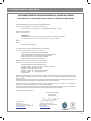
EC Declaration of Conformity pag. 49

3
EN
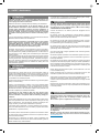
1 - SAFETY WARNINGS
ORIGINAL INSTRUCTIONS - important safety instructions. Fol-
low the instructions since incorrect installation can lead to se-
vere inquiry! Save these instructions.
Read the instructions carefully before proceeding with installation.
The design and manufacture of the devices making up the
product and the information in this manual are compliant with
current safety standards. However, incorrect installation or
programming may cause serious injury to those working on or
using the system. Compliance with the instructions provided
here when installing the product is therefore extremely impor-
tant.
If in any doubt regarding installation, do not proceed and contact the
Marantec Technical Service for clarications.
Under European legislation, an automatic door or gate system
must comply with the standards envisaged in the Directive
2006/42/EC (Machinery Directive) and in particular standards
EN 12453; EN 12635 and EN 13241-1, which enable declaration
of presumed conformity of the automation system.
Therefore, nal connection of the automation system to the electri-
cal mains, system testing, commissioning and routine maintenance
must be performed by skilled, qualied personnel, in observance of
the instructions in the “Testing and commissioning the automation
system” section.
The aforesaid personnel are also responsible for the tests required
to verify the solutions adopted according to the risks present, and for
ensuring observance of all legal provisions, standards and regula-
tions, with particular reference to all requirements of the EN12453
standard which establishes the test methods for testing door and
gate automation systems.
Before starting installation, perform the following checks and
assessments:
ensure that every device used to set up the automation system is
suited to the intended system overall. For this purpose, pay special
attention to the data provided in the “Technical specications” sec-
tion. Do not proceed with installation if any one of these devices is
not suitable for its intended purpose;
check that the devices purchased are sucient to guarantee system
safety and functionality;
perform a risk assessment, including a list of the essential safety
requirements as envisaged in Annex I of the Machinery Directive,
specifying the solutions adopted. The risk assessment is one of the
documents included in the automation system’s technical le. This
must be compiled by a professional installer.
Considering the risk situations that may arise during instal-
lation phases and use of the product, the automation system
must be installed in compliance with the following safety pre-
cautions:
never make modications to any part of the automation system other
than those specied in this manual. Operations of this type can only
lead to malfunctions. The manufacturer declines all liability for da-
mage caused by unauthorised modications to products;
if the power cable is damaged, it must be replaced by the manufac-
turer or its after-sales service, or in all cases by a person with similar
qualications, to prevent all risks;
do not allow parts of the automation system to be immersed in water
or other liquids. During installation ensure that no liquids are able to
enter the various devices;
should this occur, disconnect the power supply immediately and
contact a Marantec Service Centre. Use of the automation system in
these conditions may cause hazards;
never place automation system components near to sources of heat
or expose them to naked lights. This may damage system compo-
nents and cause malfunctions, re or hazards;
The drive shall be disconnected from its power source during
cleaning, maintenance and when replacing parts. If the discon-
nect device is not in a visible location, ax a notice stating:
“MAINTENANCE IN PROGRESS”:
connect all devices to an electric power line equipped with an
earthing system;
the product cannot be considered to provide eective protection
against intrusion. If eective protection is required, the automation
system must be combined with other devices;
the product may not be used until the automation system “commis-
sioning” procedure has been performed as specied in the “Automa-
tion system testing and commissioning” section;
the system power supply line must include a circuit breaker device
with a contact gap allowing complete disconnection in the conditions
specied by class III overvoltage;
use unions with IP55 or higher protection when connecting hoses,
pipes or cable glands;
the electrical system upstream of the automation system must com-
ply with the relevant regulations and be constructed to good wor-
kmanship standards;
this appliance can be used by children aged from 8 years and above
and persons with reduced physical, sensory or mental capabilities or
lack of experience and knowledge if they have been given supervi-
sion or instruction concerning use of the appliance in a safe way and
understand the hazards involved;
before starting the automation system, ensure that there is no-one
in the immediate vicinity;
before proceeding with any cleaning or maintenance work on the
automation system, disconnect it from the electrical mains;
special care must be taken to avoid crushing between the part ope-
rated by the automation system and any xed parts around it;
children must be supervised to ensure that they do not play with the
equipment.
that the drive cannot be used with a driven part incorporating a wi-
cket door unless the drive can only be operated with the wicket door
in the safe position;
The automation system component packaging material must
be disposed of in full observance of current local waste dispo-
sal legislation.
Marantec reserves the right to amend these instructions if ne-
cessary; they and/or any more recent versions are available at
www.marantec.com
Frequently examine the installation for imbalance where ap-
plicable and signs of wear or damage to cables, springs and
mounting.
Do not use if repair or adjustment is necessary.
ATTENTION !
ATTENTION !
ATTENTION !
ATTENTION !
ATTENTION !

4
EN
2 - INTRODUCING THE PRODUCT
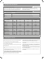
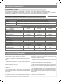
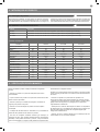
Code Description
SU500F 24 Vac gear motor with magnetic limit switches, gate maximum weight 500 Kg
SU700M 24 Vdc gear motor with mechanical limit switches, gate maximum weight 700 Kg
SU1100M 24 Vdc gear motor with mechanical limit switches, gate maximum weight 1100 Kg
2.1 - Description of the product
The gear motor COMFORT SU is intended to be installed within sy-
stems for the automation of sliding gates. The COMFORT SU gear
motors have been designed to automate sliding gates within the
weight limits indicated in the technical specications table.
The use of gear motors for applications which dier from those
indicated above is prohibited.
2.2 - Model and technical characteristics
3 - PRELIMINARY CHECKS
Before installing this product, verify and check the following steps:
- Check that the gate or door are suitable for automation
- The weight and size of the gate or door must be within the maxi-
mum permissible operating limits
- Check the presence and strength of the security mechanical stops
of the gate or door
- Check that the mounting area of the product is not subject to ood-
ing
- Conditions of high acidity or salinity or proximity to heat sources
could cause malfunction of the product
- Extreme weather conditions (for example the presence of snow,
ice, high temperature range, high temperatures) may increase the
friction and therefore the force required for the handling and initial
starting point may be higher than under normal conditions.
- Check that the manual operation of gate or door is smooth and
friction-free and there is no risk of derailment of the same
- Check that the gate or door are in equilibrium and stationary if left
in any position
- Check that the power line to supply the product is equipped with
proper grounding safety and protected by a magnetothermal and
dierential security device
- Provide the power system with a disconnecting device with a gap
of contacts enabling full disconnection under the conditions dictated
by the overvoltage category III.
- Ensure that all materials used for the installation comply with cur-
rent regulations
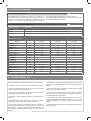
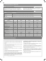
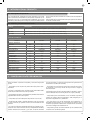
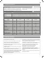
TECHNICAL DATA
MODELS SU500F SU700M SU1100M
TECHNICAL SPEC.
Speed cm/s 40 25 20
Torque Nm 23 26 38
Working cycle % 70 80 80
Control unit CBX10224F CBX10224 CBX10224
Power supply Vac (Vdc) 230(24) 230(24) 230(24)
Absorption A 1,5 1,5 1,3
Engine power W 345 345 300
Capacitor µF - - -
Thermoprotection °C 110 - -
Integrated lights - - -
Degree of protection IP 44 44 44
Dimensions (L-P-H) mm 330-210-300 330-210-300 330-210-300
Weight Kg 12,5 12,5 13
Operating temperat. °C -20+55 -20+55 -20+55
Leaves max weight Kg 500 700 1100
Sound emission level dB(A) ≤ 70 ≤ 70 ≤ 70

5
EN
ù
4 - PRODUCT INSTALLATION
4.1 - Installation
Before proceeding with the installation, check the integrity of the
product and that all components are present in the package.
Check that the gate weight respects the limit of the table (paragraph
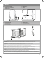
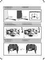
2.2) and dimensions of the gear motor are met (Fig. 1).
Fig.2 shows a typical installation:
Gear motor (1)
Photocells (2)
Columns for photocells (3)
Flashing light with antenna (4)
Key switch or digital keypad (5)
Pressure-sensitive edge (6)
The automation system must be equipped with a pressure-sen-
sitive edge protecting all possible crushing points (hands, feet,
etc.) in accordance with the requirements of the EN 13241-1
standard.
They shall state that the installer shall check that the tempera-
ture range marked on the drive is suitable for the location.
ATTENTION !
ATTENTION !
ATTENTION !
ATTENTION !
ATTENTION !
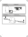
4.2 - Installing the foundation box
Verify the orientation and the overall dimensions of the base plate, x
to ground the base-plate through 4 sturdy screw-anchors or drown it
into the concrete (Fig.3).
Provide one or more corrugated duct tubes for routing the electric
cables.
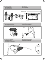
4.3 - Motor unlock
4.5 - Rack assembling
Open entirely the gate.
Put a rack element on the pinion gear and fasten it to the gate with
screw and spacing bars (Fig.10).
Move the gate manually bringing the pinion gear into line with the
last spacing bar.
Fasten the rack element for good.
4.6 - Limit switch xing
The exact dimensions of the rack must be known to allow pre-
cise calculation of the xing plate position.
With motors with integrated night lights (Night Light System)
make sure not to rip o the cable that connects the leds on the
cover with the control board. If necessary, disconnect the con-
nector shown in gure 7.
The stop lock position must assure that the limit switch brackets
don’t collide with the pinion gear. (Fig.11)
For a correct positioning of the other elements and to assure their
straightness, it is necessary to employ a rack element using it as
support and reference. It is besides necessary to assure an aperture
of 2 mm between rack and pinion gear, so that the gate weight doe-
sn’t rest on the gearmotor pinion gear.
The gate has to be equipped with stop locks at the opening and
closing, which prevent the gate derailment.
Haul the gate manually at the opening leaving, depending on the
gate weight, a crack from 30 to 50 mm between the main gate and
mechanical stop.
Fasten the limit switch bracket through the dowels so that the limit
switch is pressed (Fig.11).
Follow the instructions of the control panel and close the cover.
4.4 - Fixing the plate
Open the cover by applying leverage with a screwdriver on the re-
cesses at the sides (Fig.6).
Place the gearmotor on the plate and x the 4 nuts (Fig.8a). If the
permitted adjustment of the rack is not sucient, before tightening
the nuts the height of the gearmotor can be corrected using the four
regulator stud bolts (Fig.8b).
After the adjustment, it is important to fully tighten the nuts, making
sure that the gearmotor is rmly anchored to the ground throughout
the gate’s travel stroke.
The screws should be tightened again after the gearmotor has been
operated a few times.
Replace the cover so that the light is pointed in the required direction
(Fig.9), such as towards the passage.
To release the gearmotor remove the cap on the side (Fig.4.1) and
turn the pin with the release key or the Sub remote control (Fig.4.2).
Then turn the lever (Fig.5).

6
EN
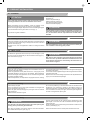
5.2 - Commissioning
Following the successful testing of all (and not just some) devices in
the system you can proceed with the commissioning.
You must prepare, and keep for 10 years, the technical le of the
system with the wiring diagram, drawing or photo of the system,
risks analysis and solutions adopted, manufacturer declaration of
conformity of all devices connected, instruction manual of each de-
vice and maintenance schedule of the system.
Fix on the gate or door a plaque indicating the automation data, the
name of the person responsible for the commissioning, the serial
number and year of construction, the CE mark.
Attach a plaque indicating the steps required to manually unlock
the system.
Implement and deliver to the end user the declaration of conform-
ity, the instructions and warnings for use for the end user and the
maintenance schedule of the system.
Make sure the user understands proper automatic, manual and
emergency operation of the automation.
Inform the end user in writing of the dangers and risks still present.
5.1 - Testing
All system components must be tested following the procedures
outlined in the respective instruction manuals.
Check that they meet the guidelines in Chapter 1 - Safety warnings
Check that the gate or door can move freely once the automation
is unlocked, and that they are in equilibrium and stationary if left in
any position.
Check the correct operation of all connected devices (photocells,
sensitive edges, emergency buttons, etc.), testing the opening,
closing and stopping of the gate or door via the connected control
devices (transmitters, buttons, switches).
Carry out measurements of the impact force, as prescribed by
standard EN12453 adjusting the functions of speed, motor force
and deceleration of the unit if the measurements do not give the
desired results until you nd the right setting.
The testing of the system must be performed by qualied techni-
cians who must perform the tests required by relevant legislation
related to risks, ensuring compliance with the provisions of the
regulations, in particular the EN12453 standard, which species the
testing methods for the automation of doors and gates.
5 - TESTING AND COMMISSIONING THE AUTOMATION SYSTEM

7
EN
5.3 - Instructions and warnings for the end user
Marantec Antriebs- und Steuerungstechnik GmbH & Co. KG pro-
duces systems for the automation of gates, garage doors, automatic
doors, shutters, parking lots and road barriers. However, Marantec
is not the manufacturer of your automation system, which is rather
the result of a process of analysis, evaluation, selection of materials,
and installation performed by your own installer. Each automated
system is unique and only your installer has the experience and pro-
fessionalism required to create a system to suit your needs, safe
and reliable over time, and carried out in a workmanlike manner, i.e.
compliant with the current regulations. Even if your automation sys-
tem meets the security level required by law, this does not exclude
the existence of “residual risks”, i.e. the possibility that it may cause
dangerous situations, usually as a result of improper or irresponsible
use; for this reason we would like to give you some suggestions:
• Before using the automation for the rst time, ask the installer to
explain the origin of residual risks (Fig.1).
• Keep this manual for future use and deliver it to any new owner of
the automation.
• Inappropriate or improper use of the automation can make it dan-
gerous: do not command the movement of the automation if people,
animals or things are in its range.
• Children: If properly designed, an automation system ensures a
high degree of security, preventing movement in the presence of
people or things with its detection systems, and ensuring always
predictable and safe activation. It is prudent to prevent children from
playing near the automation and keep remote controls out of their
reach to prevent accidental activation.
• Malfunctions: As soon as you notice any malfunctions, disconnect
the system from the power supply and operate the manual release.
Do not attempt any repairs by yourself, but require the assistance
of your installer: meanwhile, the system can operate like a non-au-
tomated opening device after releasing the motor reducer with the
release key supplied with the system.
• In case of failures or power failures: While awaiting the arrival of
your installer or the restore of the electricity, if the system is not
equipped with backup batteries, the automation can be operated as
any normal non-automated opening device. To do this, you must run
the manual release (Fig.2).
Release and manual movement: before performing this operation
pay attention that the device can be released only when the door is
stationary (Fig.2).
• Maintenance: Like any machine, your automation needs periodic
maintenance to ensure its long life and total safety. Agree with your
installer on a maintenance plan on a periodic basis; Marantec rec-
ommends a frequency of 6 months for normal domestic use, but
this period may vary depending on the intensity of use. All inspec-
tion, maintenance or repairs should be performed only by qualied
personnel.
ATTENTION !
ATTENTION !
Cleaning and user maintenance shall not be made by children
without supervision.
• Do not change the system and control or programming parameters
of the automation: the responsibility lies with your installer.
• The testing, routine maintenance and any repairs must be docu-
mented by the person who performs them, and related documents
must kept by the owner.
The only interventions that are possible for the user and should be
carried out periodically are the cleaning of the slides and photocells,
as well as the removal of any leaves or rocks that could hinder the
automation. To prevent anyone from activating the gate or door,
before proceeding, remember to release the automation and clean
only with a cloth slightly dampened with water.
A more recent version of the manual supplied may be available
for download at www.marantec.com; check for updates.
• Disposal: At the end of the automation useful life, make sure that
the dismantling is carried out by qualied personnel and the mate-
rials are recycled or disposed of according to local regulations in
force.
• Operate the gate or door (with remote control, key switch, etc..);
if everything is working properly, the gate or the door will open and
close normally, otherwise the ashing light ashes and the maneu-
ver does not start.
With the safeties out of use, the automation must be repaired as
soon as possible.
Replacing the remote control battery: if your remote control seems
to work worse or not work at all after a while, this may simply de-
pend on the exhaustion of the battery (depending on use, it may
take several months to over a year). In that case, you will see that
the conrmation of transmission light does not turn on, or comes on
only briey.
The batteries contain polluting substances: do not throw them in the
garbage but use the methods prescribed by local regulations.
Thank you for choosing Marantec; for more information feel free to
visit our website www.marantec.com.

8
DE
1
2
3
4
5
6
Sicherheitshinweise
2.1
2.2
4.1
4.2
4.3
4.4
4.5
4.6
5.1
5.2
5.3
Produkteinführung
Produktbeschreibung
Modell und technische Merkmale
Vorabkontrollen
Produktinstallation
Installation
Befestigung der Bodenplatte
Entriegeln des Getriebemotors
Befestigung der Platte
Montage der zahnstange
Befestigung der anschläge
Ab- und Inbetriebnahme
Abnahme
Inbetriebnahme
Anweisungen und hinweise für den
endbenutzer
Abbildungen
S. 9
S. 10
S. 10
S. 10
S. 10
S. 11
S. 11
S. 11
S. 11
S. 11
S. 11
S. 12
S. 12
S. 12
S. 13
S. 45
INHALTSVERZEICHNIS
7
Konformitätserklärung CE S. 49

9
DE
1 - SICHERHEITSHINWEISE
ORIGINALANWEISUNGEN – Wichtige Sicherheitsanweisun-
gen. Für die Sicherheit der Personen ist es wichtig, die folgen-
den Sicherheitsanweisungen zu befolgen. Bewahren Sie diese
Anweisungen auf.
Vor Durchführung der Installation lesen Sie die Anleitung bitte
aufmerksam durch.
Die Konstruktion und die Herstellung der Geräte, aus denen
sich das Produkt zusammensetzt, und die in diesem Handbuch
enthaltenen Informationen entsprechen den geltenden Si-
cherheitsvorschriften. Dennoch können eine falsche Installa-
tion und eine falsche Programmierung schwerwiegende Ver-
letzungen bei Personen verursachen, die die Arbeit ausführen,
und bei denen, die die Anlage benutzen werden. Aus diesem
Grund ist es wichtig, während der Installation strikt alle Anwei-
sungen in diesem Handbuch zu beachten.
Bei Zweifel jeglicher Art die Installation abbrechen und ggf. den Ma-
rantec Kundendienst zur Klärung kontaktieren.
Für die europäische Gesetzgebung muss der Einbau einer au-
tomatischen Tür oder eines automatischen Tors den Bestim-
mungen der Richtlinie 2006/42/EG (Maschinenrichtlinie) und im
Besonderen den Normen EN 12453, EN 12635 und EN 13241-1
entsprechen, die eine Konformitätserklärung der Automatisie-
rung ermöglichen.
In Anbetracht dessen müssen die endgültige Verbindung der Auto-
matisierung ans Stromnetz, die Endabnahme der Anlage, die Inbe-
triebnahme und die regelmäßige Wartung von qualiziertem und
erfahrenem Personal entsprechend den Anleitungen unter „Prüfung
und Inbetriebnahme der Automatisierung“ durchgeführt werden.
Außerdem muss das Personal auch die vorgesehenen Tests nach
den vorhandenen Risiken festlegen und die Einhaltung der Gesetze,
Vorschriften und Regeln überprüfen: insbesondere die Einhaltung
der Norm EN12453, welche die Prüfverfahren für die Automatisie-
rung von Türen und Toren festlegt.
Vor Installationsbeginn folgende Analysen und Prüfungen dur-
chführen:
Sicherstellen, dass die für die Automatisierung vorgesehenen
Vorrichtungen für die zu realisierende Anlage geeignet sind. Die-
sbezüglich aufmerksam die im Kapitel „Technische Eigenschaften“
aufgeführten Daten prüfen. Die Installation nicht durchführen, wenn
auch nur eine der Vorrichtungen nicht für den Gebrauch geeignet ist.
Sicherstellen, dass die erworbenen Vorrichtungen ausreichend sind,
um die Sicherheit und Funktion der Anlage zu gewährleisten.
Die Risikoanalyse durchführen, welche auch die Liste der Si-
cherheitsanforderungen, aufgeführt in Anhang I der Maschinenricht-
linie, beinhalten muss, und die angewandten Lösungen nennen.Die
Risikoanalyse ist eine der Unterlagen, aus denen sich die techni-
schen Unterlagen der Automatisierung zusammensetzen. Diese
müssen von einem erfahrenen Installateur ausgefüllt werden.
In Anbetracht der Gefahrensituationen, die bei Installation und
Benutzung des Produktes auftreten können, muss die Automa-
tisierung unter Berücksichtigung folgender Hinweise installiert
werden:
Keine Änderungen an der Automatisierung vornehmen, wenn diese
nicht in diesem Handbuch vorgesehen sind. Diese können nur zu
Funktionsstörungen führen. Der Hersteller übernimmt keine Haftung
für Schäden, die durch eigenmächtige Änderungen am Produkt ve-
rursacht wurden.
Ist das Stromkabel beschädigt, muss es vom Hersteller, seinem
technischen Kundendienst oder einer ähnlich qualizierten Person
ersetzt werden, um Gefährdungen zu vermeiden;
Die einzelnen Komponenten der Automatisierung dürfen nicht in
Wasser oder andere Flüssigkeiten getaucht werden. Bei der In-
stallation darauf achten, dass keine Flüssigkeit ins Innere der Vor-
richtungen dringt.
Sollten Flüssigkeiten ins Innere der Automatisierungskomponenten
dringen, sofort die Stromzufuhr abschalten und sich an den Maran-
tec Kundendienst wenden. Die Benutzung der Automatisierung in
derartigen Situationen kann gefährlich sein.
Die einzelnen Komponenten weder Wärmequellen noch oenen
Flammen aussetzen. Dadurch können Schäden, Störungen und
Gefahrensituationen entstehen oder ein Brand ausbrechen
Die Einheit ist während der Reinigung, Wartung und Auswe-
chslung von Bestandteilen von der Speisung abzutrennen.
Sollte die Abschaltvorrichtung nicht sichtbar sein, ein Schild
mit der Aufschrift „IN WARTUNG“ anbringen.
Alle Vorrichtungen müssen mit einer Stromleitung verbunden wer-
den, die sicher geerdet ist.
Dieses Produkt kann nicht als ausreichendes System für den
Einbruchsschutz angesehen werden. Wenn Sie sich ausreichend
schützen wollen, müssen andere Vorrichtungen in die Automatisie-
rung integriert werden.
Wie im Absatz „Prüfung und Inbetriebnahme der Automatisierung“
vorgesehen, darf das Produkt erst nach der „Inbetriebnahme“ der
Automatisierung benutzt werden.
Im Stromnetz der Anlage eine Abschaltvorrichtung mit ausreichen-
dem Önungsabstand der Kontakte vorsehen, die, wie von der
Überspannungskategorie III gefordert, die komplette Abschaltung
erlaubt.
Verwenden Sie für die Verbindung von steifen und exiblen Rohren
oder Kabeldurchgängen Anschlüsse mit dem Schutzgrad IP55 oder
höher.
Die elektrische Anlage vor der Automatisierung muss den geltenden
Bestimmungen entsprechen und fachgerecht ausgeführt sein.
Das Gerät kann von Kindern im Alter von nicht weniger als 8 Jahren
und von Personen mit beschränkten körperlichen, sensoriellen und
geistigen Fähigkeiten oder ohne Erfahrung bzw. ohne das notwen-
dige Bewußtsein verwendet werden, vorausgesetzt, dass sie dabei
überwacht werden oder dass sie Anweisungen über den sicheren
Gebrauch des Gerätes und das Verständnis der damit verbundenen
Gefahren erhalten haben;
Vergewissern Sie sich vor der Inbetriebsetzung der Automatisie-
rung, dass sich keine Personen in unmittelbarer Nähe benden;
Vor jeder Reinigung und Wartung ist die Automatisierung vom
Stromnetz zu trennen;
Besondere Vorsicht ist geboten, um Quetschungen zwischen dem
geführten Teil und festen Elementen in der unmittelbaren Nähe zu
vermeiden;
Kinder sollten beaufsichtigt werden, um sicherzustellen, dass sie
nicht mit dem Gerät spielen.
Das Gerät darf mit einer automatisierten Tür mit eingebauter Fuß-
gängertür nicht verwendet werden.
ACHTUNG !
ACHTUNG !
ACHTUNG !
ACHTUNG !
ACHTUNG !
Die Anlage ist regelmäßig dahingehend zu prüfen, dass keine
Unwucht und Zeichen einer mechanischen Abnutzung, sowie
beschädigte Kabel, Federn und Stützelemente vorhanden sind.
Verwenden Sie nicht, wenn eine Reparatur oder Einstellung er-
forderlich ist.
Das Verpackungsmaterial aller Automatisierungskomponenten
muss entsprechend den örtlichen Bestimmungen entsorgt wer-
den.
Marantec behält sich vor, diese Anweisungen notfalls zu än-
dern; diese Anweisungen und/oder eine neuere Version ben-
den sich auf der Website www.marantec.com

10
DE
2 - PRODUKTEINFÜHRUNG
Artikelnummer Descripción
SU500F Getriebemotor 24 Vac mit magnetisch Endanschlägen, max. Torgewicht 500 kg
SU700M Getriebemotor 24 Vdc mit mechanischen Endanschlägen, max. Torgewicht 700 kg
SU1100M Getriebemotor 24 Vdc mit mechanischen Endanschlägen, max. Torgewicht 1100 kg
2.1 - Produktbeschreibung
Die Getriebemotoren COMFORT SU sind für die Installation in
Schiebetor-Antriebsanlagen mit einer Stromversorgung von 24 Vdc
bestimmt. Die Getriebemotoren COMFORT SU sind dazu konzipiert
und gebaut, um im Rahmen der Gewichtsgrenzwerte laut Tabelle der
technischen Angaben auf Schiebetore montiert zu werden.
Die Verwendung der Getriebemotoren für andere Anwendungen als
den oben angegebenen ist verboten.
2.2 - Modell und technische Merkmale
3 - VORABKONTROLLEN
Vor der Installation bitte folgende Punkte prüfen und kontrollieren:
- Kontrollieren ob sich Tor oder Tür für die Automatisierung eignen.
- Gewicht und Größe des Tors oder der Tür müssen innerhalb der
maximal zulässigen Einsatzgrenzen liegen
- Kontrolle des Vorhandenseins und der Stärke der mechanischen
Sicherheitsanschläge des Tors oder der Tür.
- Sicherstellen, dass der Befestigungsbereich nicht überutet wer-
den kann.
- Überhöhter Säure- oder Salzgehalt oder die Nähe von Wärme-
quellen können Fehlfunktion des Produktes verursachen.
- bei extremen klimatischen Verhältnissen (wie z.B. Schnee, Eis,
hohe Temperaturunterschiede, hohe Temperaturen) könnten sich
die Reibungen verstärken, deshalb könnte der Kraftaufwand für
die Bewegung und das Anlaufmoment höher sein als im Normal-
zustand.
- Kontrollieren, dass die manuelle Bewegung des Tors oder der Tür
üssig und ohne Reibungspunkte ist und keine Entgleisungsgefahr
besteht.
- Prüfen, dass sich das Tor oder die Tür im Gleichgewicht bendet
und folglich in jeder Stellung stillsteht.
- Prüfen, dass die Stromleitung für den Anschluss des Produkts
über eine gesicherte Erdung verfügt und mit einem Leitungsschutz-
und Dierentialschalter geschützt ist.
– Im Stromnetz der Anlage eine Abschaltvorrichtung mit ausrei-
chender Önungsweite der Kontakte vorsehen, die, wie von der
Überspannungskategorie III gefordert, die komplette Abschaltung
erlaubt.
- Sicherstellen, dass das gesamte benutzte Material den geltenden
Normen entspricht.
TECHNISCHE DATEN
MODELL SU500F SU700M SU1100M
TECH. MERKMALE
Geschwindigkeit cm/s 40 25 20
Drehmoment Nm 23 26 38
Arbeitszyklus % 70 80 80
Central Command CBX10224F CBX10224 CBX10224
Versorgung Vac (Vdc) 230(24) 230(24) 230(24)
Leistungsaufnahme A 1,5 1,5 1,3
Motorleistung W 345 345 300
Kondensator µF - - -
Thermoschutz °C 110 - -
Einbauleuchte - - -
Schutzgrad IP 44 44 44
Größe (L - P - H) mm 330-210-300 330-210-300 330-210-300
Gewicht Kg 12,5 12,5 13
Betriebstemperatur °C -20+55 -20+55 -20+55
Maximale Türgewicht Kg 500 700 1100
Aussendung Schallpegel dB(A) ≤ 70 ≤ 70 ≤ 70

11
DE
ù
4 - PRODUKTINSTALLATION
4.1 - Installation
Prüfen Sie vor dem Einbau die Unversehrtheit des Produktes sowie
ob alle Bauteile in der Packung vorhanden sind.
Außerdem ist zu prüfen, dass das Gewicht des Tors der Angabe in
der Tabelle (Abs. 2.2) entspricht und dass die äußeren Abmessun-
gen des Getriebemotors eingehalten werden (Abb.1).
Abb. 2 zeigt ein typisches Installationsbeispiel:
Getriebemotoren (1)
Fotozellen (2)
Säulen für Fotozellen (3)
Blinkleuchte mit integrierter Antenne (4)
Schlüsselwahlschalter oder digitale Tastatur (5)
Druckempndliche Kante (6)
Der Antrieb muss zum Schutze vor allen möglichen Quetsch-
stellen (für Hände, Füße...) notwendigerweise mit einer Si-
cherheitsleiste im Sinne der Bestimmungen der Norm EN
13241-1 ausgestattet sein.
Der Installateur muss prüfen, dass der auf dem Antrieb ange-
gebene Temperaturbereich für die Position, an der er installiert
werden muss, geeignet ist.
ACHTUNG !
ACHTUNG !
ACHTUNG !
ACHTUNG !
ACHTUNG !
4.2 - Befestigung der Bodenplatte
Die äußeren Abmessungen der Bodenplatte und ihre Ausrichtung
prüfen, die Bodenplatte mit vier robusten Spreizdübeln am Bo-
den befestigenoder in Beton einlassen (Abb.3). Ein oder mehrere
Wellrohre für die Durchführung der Stromkabel vorbereiten.
4.5 - Montage der zahnstange
Das Tor gänzlich önen.
Ein Zahnstangenelement am Ritzel aufstützen und dieses mit
Schrauben und Distanzstücken am Tor befestigen (Abb. 10).
Das Tor von Hand bewegen, bis sich der Ritzel auf der Höhe des
letzten Distanzstücks bendet.
Das Zahnstangenelement endgültig arretieren.
4.3 - Entriegeln des Getriebemotors
4.6 - Befestigung der anschläge
Es ist notwendig, die Abmessungen der Zahnschiene zu ken-
nen, um die Position der Befestigungsplatte genauestens be-
rechnen zu können.
Bei Antrieben mit eingebauten Nachtlichtern (Night Light Sy-
stem) vorsichtig vorgehen, um das Kabel nicht abz reißen, das
die Deckellichter mit dem Steuergerät verbindet. Eventuell den
in der Abb.7 gezeigten Verbinder abtrennen.
Die Position des Anschlags ist so zu wählen, dass die Anschlagbügel
keinesfalls gegen den Ritzel stoßen. (Abb.11)
Zur Gewährleistung der korrekten Positionierung und Geradlinigkeit
der restlichen Elemente muss ein Element nur als Auage und Bezug
eingesetzt werden. Überdies muss zwischen Zahnstange und Ritzel
ein Spiel von 2 mm verbleiben, damit das Gewicht des Tores nicht
auf dem Ritzel des Torantriebs lastet.
Das Tor muss mit Anschlägen zur Begrenzung der Önungs-
und Schließbewegung ausgestattet sein, um ein Entgleisen zu
verhindern.
Das Tor von Hand in Önungsstellung bringen und - je nach
seinem Gewicht - einen Freiraum von 30 bis 50 mm zwischen Tor und
Anschlag belassen.
Den Anschlagbügel mit Stiften befestigen (Abb.11), so dass der
Mikro-Endschalter gedrückt wird.
Diesen Vorgang auch bei geschlossenem Tor ausführen.
Die Anleitungen der Schaltkarte ausführen und abschließend
den Deckel wieder schließen und befestigen.
4.4 - Befestigung der Platte
Den Deckel önen und dazu mit einem Schraubenzieher an den
seitlichen Aufnahmen ausrücken (Abb.6).
Den Antrieb auf die Platte setzen und die 4 Muttern befestigen
(Abb.8a). Falls die von der Zahnschiene erlaubte Regelung unzurei-
chend sein sollte, besteht die Möglichkeit, die Höhe des Antriebs vor
dem Festziehen der Muttern durch Einwirken auf die vier Regelstifte
auszugleichen (Abb.8b).
Es ist wichtig, nach vollendetem Vorgang die Muttern fest zu span-
nen und sich zu vergewissern, dass der Antrieb während des ge-
samten Torlaufweges gut am Boden befestigt ist.
Es wird empfohlen, die Schrauben nach einigen Manövern des An-
triebes erneut zu spannen.
Den Deckel wieder so positionieren, dass das Licht in die gewün-
schte Richtung gerichtet wird (Abb.9), z.B. in die Durchfahrtsrichtung.
Um den Antrieb zu entsperren, den seitlichen Stopfen önen
(Abb.4.1) und den Bolzen mit dem Entriegelungsschlüssel oder mit
der Sub-Fernbedienung drehen (Abb.4.2). Daraufhin den Hebel
drehen (Abb.5).

12
DE
12
5.2 - Inbetriebnahme
Nach positivem Test aller (und nicht nur einiger) Vorrichtungen der
Anlage, kann die Inbetriebnahme vorgenommen werden.
Die technischen Unterlagen der Anlage müssen ausgestellt und
für 10 Jahre aufbewahrt werden, sie umfassen den Schaltplan, die
Zeichnung oder ein Foto der Anlage, die Risikoanalyse und die je-
weiligen Lösungen, die Konformitätserklärung des Herstellers, die
Gebrauchsanweisungen einer jeden Vorrichtung und den War-
tungsplan der Anlage.
Am Tor oder an der Tür ein Schild mit den Daten der Automation,
dem Namen des Verantwortlichen der Inbetriebnahme, der Serien-
nummer, dem Herstellungsjahr sowie dem CE-Zeichen anbringen.
Ein Schild mit den notwendigen Handgrien zur manuellen Entrie-
gelung der Anlage anbringen.
Die Konformitätserklärung ausfüllen und dem Endbenutzer zusam-
men mit der Gebrauchsanweisung und dem Wartungsplan der An-
lage aushändigen.
Sicherstellen, dass der Benutzer den automatischen und manuellen
Betrieb und die Notausschaltung des Antriebs verstanden hat.
Den Endbenutzer auch schriftlich über Gefahren und Risiken infor-
mieren.
5.1 - Test
Alle Komponenten der Anlage müssen entsprechend der jeweiligen
Anweisungen der Handbücher endgeprüft werden.
Kontrollieren, dass die Anweisungen des Kapitels 1 beachtet wer-
den – Anweisungen zur Sicherheit
Kontrollieren, dass sich das Tor oder die Tür nach der Entriegelung
frei bewegen können und sich in jeder Stellung im Gleichgewicht
benden und stillstehen.
Die korrekte Funktion aller verbundenen Vorrichtungen (Fotozellen,
Druckleisten, Notschalter und anderes) kontrollieren, indem man
mit den Bedienvorrichtungen alle Proben der Önung, Schließung
und Blockierung des Tors oder der Tür durchführt (Sender, Tasten,
Wahlschalter).
Die Messungen der Aufprallstärke nach EN12453 durchführen, da-
bei Geschwindigkeit, Motorkraft und Verlangsamungen des Steuer-
geräts einstellen, falls die Messungen nicht die gewünschten Werte
zeigen.
Die Endabnahme der Anlage muss von einem qualiziertem Tech-
niker durchgeführt werden, der alle von der entsprechenden Norm
geforderten Proben bzgl. der bestehenden Risiken ausführen
muss, insbesondere entsprechend EN12453, welche die Testme-
thoden für Automationen von Türen und Tore enthält.
5 – TEST UND INBETRIEBNAHME DER AUTOMATION

13
DE
5.3 - Anweisungen und hinweise für den endbenutzer
Marantec Antriebs- und Steuerungstechnik GmbH & Co. KG stellt
Automationssysteme für Tore, Garagentore, automatische Türen,
Rollläden, sowie Schranken für Parkplätze oder Straßensperren
her. Marantec ist jedoch nicht der Hersteller Ihrer Automation. Sie
ist das Ergebnis von Analysen, Auswertung, Materialwahl und Anla-
genausführung des Installateurs Ihres Vertrauens Jede Automation
ist einmalig und nur Ihr Installateur besitzt die Erfahrung und not-
wendigen Kenntnisse zur Ausführung einer auf Ihre Anforderungen
zugeschnittenen Anlage, die langfristig sicher und zuverlässig und
vor allem sachgerecht arbeitet und den geltenden Bestimmungen
entspricht. Auch wenn Ihre Automation die Sicherheitsanforderun-
gen der Bestimmungen erfüllt, schließt dies ein «Restrisiko» nicht
aus. Das bedeutet, das Gefahrensituationen entstehen können, die
normalerweise auf eine unvorsichtige und sogar falsche Benutzung
zurückzuführen sind. Eben aus diesem Grund möchten wir Ihnen
einige Ratschläge zur Verhaltensweise mitgeben:
• Vor der ersten Benutzung der Automation lassen Sie sich vom Ins-
tallateur die Ursache der Restrisiken erklären (Abb.1).
• Heben Sie die Gebrauchsanleitung für spätere Zweifel auf und
übergeben Sie diese einem eventuellen neuen Eigentümer der Au-
tomation.
• Eine unvorsichtige und unsachgemäße Benutzung der Automation
kann sie zu einer Gefahr werden lassen: veranlassen Sie nicht die
Bewegung der Automation, wenn sich Personen, Tiere oder Gegen-
stände in ihrem Aktionskreis benden.
• Kinder: Wenn eine Automationsanlage sachgerecht geplant wurde,
gewährleistet sie auch eine hohe Sicherheitsstufe und verhindert bei
Anwesenheit von Personen oder vorhandenen Gegenständen mit
ihren Erfassungssystemen die Bewegung, dies garantiert die immer
voraussehbare und sichere Einschaltung. Vorsichtshalber sollte
man jedoch Kindern das Spielen in der Nähe der Automation ver-
bieten und um ungewollte Einschaltungen zu verhindern, sollten die
Fernbedienungen nicht in ihrer Reichweite bleiben.
• Störungen: sobald die Automation ein ungewöhnliches Verhalten
aufweist, den Strom von der Anlage nehmen und die Entriegelung
von Hand vornehmen. Keinen Reparaturversuch vornehmen, wen-
den Sie sich an den Installateur Ihres Vertrauens: in der Zwischen-
zeit kann die Anlage nach der Entriegelung des Getriebemotors mit
dem entsprechenden Schlüssel, der zum Lieferumfang gehört, mit
nicht automatisierter Önung arbeiten.
• Bei Beschädigungen oder Stromausfall: Während Sie auf den Ins-
tallateur oder die Stromrückkehr warten und die Anlage verfügt über
keine Puerbatterie, kann die Automation wie jede andere nicht au-
tomatisierte Önung arbeiten. Hierfür muss sie von Hand entriegelt
werden (Abb.2).
Entriegelung und manuelle Bewegung: vor diesem Eingri darauf
achten, dass die Entriegelung nur bei stillstehendem Flügel erfolgen
kann (Abb.2).
• Wartung: Damit sie möglichst lange und vollkommen sicher ar-
beitet, bedarf Ihre Automation, wie jedes andere Gerät, einer re-
gelmäßigen Wartung. Vereinbaren Sie mit Ihrem Installateur einen
Wartungsplan mit regelmäßigen Abständen. Marantec empehlt bei
einem normalen Hausgebrauch alle 6 Monate einen Eingri, die-
se Zeitspanne kann sich je nach Häugkeit der Benutzung ändern.
Jede Überprüfung, Wartung oder Reparatur darf nur durch fachlich
qualiziertes Personal erfolgen.
ACHTUNG !
ACHTUNG !
Die Reinigungs- und Wartungsarbeiten dürfen von Kindern
ohne Überwachung nicht durchgeführt werden.
• Die Anlage, die Programmierparameter und die Regulierung der
Automation dürfen in keiner Weise verändert werden: die Verant-
wortung trägt Ihr Installateur.
Auf der Website www.marantec.com könnte das Downlo-
ad einer aktuelleren Version des mitgelieferten Handbuches
verfügbar sein; eine solche Verfügbarkeit ist bitte zu prüfen.
• Die Endabnahme, die regelmäßigen Wartungen und eventuelle
Reparaturen müssen durch den Ausführenden belegt werden, diese
Belege müssen vom Besitzer der Anlage aufbewahrt werden.
Die einzigen Eingrie, die Sie ausführen können und wir empfehlen
Ihnen, diese vorzunehmen, ist das Reinigen der Glasscheiben der
Fotozellen und das Entfernen von Laub oder Steinen, die eine Be-
hinderung der Automation bilden könnten. Vor diesen Eingrien die
Automation entriegeln, damit niemand das Tor oder die Tür betäti-
gen kann und für die Reinigung nur ein leicht mit Wasser angefeuch-
tetes Tuch verwenden.
• Entsorgung: Wenn die Automation nicht mehr einsatzfähig ist, sor-
gen Sie dafür, dass sie durch fachlich qualiziertes Personal abge-
baut und das Material entsprechend den örtlich geltenden Bestim-
mungen wiederverwertet oder entsorgt wird.
• Die Bedienung des Tors oder der Tür (mit Fernbedienung, mit
Schlüssel-Wahlschalter, usw.) betätigen; wenn alles in Ordnung ist,
önet oder schließt sich das Tor oder die Tür ganz normal, andern-
falls blinkt das Blinklicht einige Male und die Bewegung wird nicht
ausgeführt.
Wenn die Sicherheiten nicht mehr arbeiten, muss die Automation
umgehend repariert werden.
Batterieaustausch der Fernbedienung: falls Ihre Funkbedienung
nach einiger Zeit nicht mehr gut funktionieren sollte oder überhaupt
nicht mehr funktioniert, könnte dies einfach an der leeren Batterie
liegen (vom Gebrauch abhängig, sie kann für einige Monate und bis
über ein Jahr reichen). Sie merken es an der Tatsache, dass sich
die Bestätigungsanzeige der Übertragung nicht oder nur für einen
kurzen Moment einschaltet.
Die Batterien enthalten schädliche Substanzen: nicht in den Haus-
müll werfen, sondern sie nach den örtlich vorgesehenen Bestim-
mungen entsorgen.
Wir danken Ihnen, dass Sie Marantec gewählt haben und la-
den Sie ein, für weitere Informationen unsere Internetseite
www.marantec.com zu besuchen.

IT
14
1
2
3
4
5
6
Avvertenze per la sicurezza
2.1
2.2
4.1
4.2
4.3
4.4
4.5
4.6
5.1
5.2
5.3
Introduzione al prodotto
Descrizione del prodotto
Modello e caratteristiche tecniche
Veriche preliminari
Installazione del prodotto
Installazione
Fissaggio della piastra di fondazione
Sblocco del motoriduttore
Fissaggio della piastra
Fissaggio della cremagliera
Fissaggio dei necorsa
Collaudo e messa in servizio
Collaudo
Messa in servizio
Istruzioni ed avvertenze per l’utente nale
Immagini
pag. 15
pag. 16
pag. 16
pag. 16
pag. 16
pag. 17
pag. 17
pag. 17
pag. 17
pag. 17
pag. 17
pag. 17
pag. 18
pag. 18
pag. 18
pag. 19
pag. 45
INDICE
7
Dichiarazione CE di conformità pag. 49

IT
15
SU500F
1 - AVVERTENZE PER LA SICUREZZA
ISTRUZIONI ORIGINALI – importanti istruzioni di sicurezza. Se-
guire tutte le istruzioni perchè una scorretta installazione può
portare a lesioni gravi! Conservare queste istruzioni.
Leggere attentamente le istruzioni prima di eseguire l’installazione.
La progettazione e la fabbricazione dei dispositivi che com-
pongono il prodotto e le informazioni contenute nel presente
manuale rispettano le normative vigenti sulla sicurezza. Ciò
nonostante un’installazione e una programmazione errata pos-
sono causare gravi ferite alle persone che eseguono il lavoro
e a quelle che useranno l’impianto. Per questo motivo, durante
l’installazione, è importante seguire attentamente tutte le istru-
zioni riportate in questo manuale.
Non procedere con l’installazione se si hanno dubbi di qualunque
natura e richiedere eventuali chiarimenti al Servizio Assistenza Ma-
rantec.
Per la legislazione Europea la realizzazione di una porta au-
tomatica o un cancello automatico deve rispettare le norme
previste dalla Direttiva 2006/42/CE (Direttiva Macchine) e in
particolare, le norme EN 12453; EN 12635 e EN 13241-1, che
consentono di dichiarare la conformità dell’automazione.
In considerazione di ciò, il collegamento denitivo dell’automatismo
alla rete elettrica, il collaudo dell’impianto, la sua messa in servizio
e la manutenzione periodica devono essere eseguiti da personale
qualicato ed esperto, rispettando le istruzioni riportate nel riquadro
“Collaudo e messa in servizio dell’automazione”.
Inoltre, egli dovrà farsi carico di stabilire anche le prove previste in
funzione dei rischi presenti e dovrà vericare il rispetto di quanto
previsto da leggi, normative e regolamenti: in particolare, il rispetto
di tutti i requisiti della norma EN12453 che stabilisce i metodi di pro-
va per la verica degli automatismi per porte e cancelli.
Prima di iniziare l’installazione, eettuare le seguenti analisi e
veriche:
vericare che i singoli dispositivi destinati all’automazione siano
adatti all’impianto da realizzare. Al riguardo, controllare con partico-
lare attenzione i dati riportati nel capitolo “Caratteristiche tecniche”.
Non eettuare l’installazione se anche uno solo di questi dispositivi
non è adatto all’uso;
vericare se i dispositivi acquistati sono sucienti a garantire la si-
curezza dell’impianto e la sua funzionalità;
eseguire l’analisi dei rischi che deve comprendere anche l’elenco dei
requisiti essenziali di sicurezza riportati nell’Allegato I della Direttiva
Macchine, indicando le soluzioni adottate. L’analisi dei rischi è uno
dei documenti che costituiscono il fascicolo tecnico dell’automazio-
ne. Questo dev’essere compilato da un installatore professionista.
Considerando le situazioni di rischio che possono vericarsi
durante le fasi di installazione e di uso del prodotto è necessa-
rio installare l’automazione osservando le seguenti avvertenze:
non eseguire modiche su nessuna parte dell’automatismo se non
quelle previste nel presente manuale. Operazioni di questo tipo
possono solo causare malfunzionamenti. Il costruttore declina ogni
responsabilità per danni derivanti da prodotti modicati arbitraria-
mente;
evitare che le parti dei componenti dell’automazione possano venire
immerse in acqua o in altre sostanze liquide. Durante l’installazio-
ne evitare che i liquidi possano penetrare all’interno dei dispositivi
presenti;
se il cavo di alimentazione risulta danneggiato esso deve essere
sostituito dal costruttore o dal suo servizio di assistenza tecnica o
comunque da una persona con qualica similare in modo da preve-
nire ogni rischio;
se sostanze liquide penetrano all’interno delle parti dei componenti
dell’automazione, scollegare immediatamente l’alimentazione elet-
trica e rivolgersi al Servizio Assistenza Marantec. L’utilizzo dell’auto-
mazione in tali condizioni può causare situazioni di pericolo;
non mettere i vari componenti dell’automazione vicino a fonti di ca-
lore né esporli a amme libere. Tali azioni possono danneggiarli ed
essere causa di malfunzionamenti, incendio o situazioni di pericolo;
L’unità deve essere scollegata dalla fonte di alimentazione du-
rante la pulizia, la manutenzione e la sostituzione di componen-
ti. Se il dispositivo di sconnessione non è a vista, apporre un
cartello con la seguente dicitura: “MANUTENZIONE IN
CORSO”;
tutti i dispositivi devono essere collegati ad una linea di alimentazio-
ne elettrica dotata di messa a terra di sicurezza;
il prodotto non può essere considerato un ecace sistema di prote-
zione contro l’intrusione. Se desiderate proteggervi ecacemente, è
necessario integrare l’automazione con altri dispositivi;
il prodotto può essere utilizzato esclusivamente dopo che è stata
eettuata la “messa in servizio” dell’automazione, come previsto nel
paragrafo “Collaudo e messa in servizio dell’automazione”;
prevedere nella rete di alimentazione dell’impianto un dispositivo di
disconnessione con una distanza di apertura dei contatti che con-
senta la disconnessione completa nelle condizioni dettate dalla ca-
tegoria di sovratensione III;
per la connessione di tubi rigidi e essibili o passacavi utilizzare rac-
cordi conformi al grado di protezione IP55 o superiore;
l’impianto elettrico a monte dell’automazione deve rispondere alle
vigenti normative ed essere eseguito a regola d’arte;
l’apparecchio può essere utilizzato da bambini di età non inferiore a
8 anni e da persone con ridotte capacità siche, sensoriali o mentali,
o prive di esperienza o della necessaria consapevolezza, purché
sotto sorveglianza oppure dopo che le stesse abbiano ricevuto istru-
zioni relative all’uso sicuro dell’apparecchio e alla comprensione dei
pericoli ad esso inerenti;
prima di avviare l’automazione assicurarsi che le persone non siano
nelle immediate vicinanze;
prima di procedere a qualsiasi operazione di pulizia e manutenzione
dell’automazione eseguire la disconnessione dalla rete elettrica;
fare particolare attenzione per evitare lo schiacciamento tra la parte
guidata ed eventuali elementi ssi circostanti;
i bambini devono essere sorvegliati per sincerarsi che non giochino
con l’apparecchio.
l’apparecchio non può essere utilizzato con una porta guidata che
incorpora una porte pedonale.
ATTENZIONE !
Esaminare periodicamente l’impianto per vericare la presenza
di sbilanciamenti e segni di usura meccanica, danneggiamento
di cavi, molle, parti di sostegno.
Non utilizzare se è necessaria riparazione o regolazione.
Il materiale dell’imballaggio di tutti i componenti dell’automa-
zione deve essere smaltito nel pieno rispetto della normativa
presente a livello locale.
Marantec si riserva il diritto di modicare le presenti istruzioni
qualora necessario, queste e/o versione superiore si possono
trovare sul sito
ATTENZIONE !
ATTENZIONE !
ATTENZIONE !
ATTENZIONE !

IT
16
2 - INTRODUZIONE AL PRODOTTO
Codice Descrizione
SU500F Motoriduttore 24 Vac con necorsa magnetici, peso massimo cancello 500 Kg
SU700M Motoriduttore 24 Vdc con necorsa meccanici, peso massimo cancello 700 Kg
SU1100M Motoriduttore 24 Vdc con necorsa meccanici, peso massimo cancello 1100 Kg
DATI TECNICI
MODELLO SU500F SU700M SU1100M
SPECIFICHE TECNICHE
Velocità cm/s 40 25 20
Coppia Nm 23 26 38
Ciclo di lavoro % 70 80 80
Centrale di comando CBX10224F CBX10224 CBX10224
Alimentazione Vac (Vdc) 230(24) 230(24) 230(24)
Assorbimento motore A 1,5 1,5 1,3
Potenza assorbita W 345 345 300
Condensatore µF - - -
Termoprotezione °C 110 - -
Luce integrata - - -
Grado di protezione IP 44 44 44
Dimensioni (L-P-H) mm 330-210-300 330-210-300 330-210-300
Peso Kg 12,5 12,5 13
Temp. di esercizio °C -20+55 -20+55 -20+55
Peso massimo anta Kg 500 700 1100
Livello emissione sonora dB(A) ≤ 70 ≤ 70 ≤ 70
2.1 - Descrizione del prodotto
2.2 - Modello e caratteristiche tecniche
3 - VERIFICHE PRELIMINARI
Prima di installare il prodotto vericare e controllare i seguenti punti:
- Controllare che il cancello o la porta siano adatti ad essere auto-
matizzati
- Il peso e la dimensione del cancello o della porta devono rientrare
nei limiti d’impiego massimi consentiti
- Controllare la presenza e la solidità degli arresti meccanici di sicu-
rezza del cancello o della porta
- Vericare che la zona di ssaggio del prodotto non sia soggetta
ad allagamenti
- Condizioni di elevata acidità o salinità o la vicinanza a fonti di calo-
re potrebbero causare malfunzionamenti del prodotto
- In caso di condizioni climatiche estreme (per esempio in presenza
di neve, ghiaccio, elevata escursione termica, temperature eleva-
te) gli attriti potrebbero aumentare e quindi la forza necessaria per
la movimentazione e lo spunto iniziale potrebbe essere superiori a
quella necessaria in condizioni normali.
- Controllare che la movimentazione manuale del cancello o della
porta sia uida e priva di zone di maggiore attrito o vi sia rischio di
deragliamento dello stesso
- Controllare che il cancello o la porta siano in equilibrio e rimanga-
no quindi fermi se lasciati in qualsiasi posizione
- Vericare che la linea elettrica a cui sarà collegato il prodotto sia
provvista di opportuna messa a terra di sicurezza e protetta da un
dispositivo magnetotermico e dierenziale
- Prevedere nella rete di alimentazione dell'impianto un dispositi-
vo di disconnessione con una distanza di apertura dei contatti che
consenta la disconnessione completa nelle condizioni dettate dalla
categoria di sovratensione III.
- Vericare che tutto il materiale utilizzato per l’installazione sia con-
forme alle normative vigenti
I motoriduttori COMFORT SU sono destinati all’installazione in
impianti di automazione per cancelli scorrevoli. I motoriduttori
COMFORT SU sono progettati e costruiti per il montaggio su can-
celli scorrevoli nei limiti di peso riportati nella tabella delle speci-
che tecniche. E’ vietato l’utilizzo dei motoriduttori per applicazioni
dierenti da quelle sopra indicate.

17
IT
ù
4 - INSTALLAZIONE DEL PRODOTTO
4.2 - Fissaggio della piastra di fondazione
Vericare le dimensioni d’ingombro della piastra di base e l’orienta-
mento, quindi ssarla a terra mediante 4 robusti tasselli ad espansio-
ne oppure annegarla nel calcestruzzo (Fig.3).
Prevedere uno o più tubi corrugati per il passaggio dei cavi elettrici.
4.3 - Sblocco del motoriduttore
Per sbloccare il motoriduttore aprire il tappo a lato (Fig.4.1) e girare
il perno con la chiave di sblocco o con il telecomando Sub (Fig.4.2).
Successivamente ruotare la leva (Fig.5).
4.4 - Fissaggio della piastra
4.5 - Fissaggio della cremagliera
Portare il cancello in completa apertura.
Appoggiare un elemento di cremagliera al pignone e ssare lo stes-
so con viti e distanziali al cancello (Fig.10).
Spostare manualmente il cancello portando il pignone in corrispon-
denza dell’ultimo distanziale.
Fissare l’elemento di cremagliera denitivamente.
4.6 - Fissaggio dei necorsa
È necessario conoscere le dimensioni della cremagliera per
poter calcolare con precisione il posizionamento della piastra
di ssaggio.
4.1 - Installazione
ATTENZIONE !
ATTENZIONE !
ATTENZIONE !
ATTENZIONE !
Prima di procedere con l’installazione, vericare l’integrità del pro-
dotto e che tutti i componenti siano presenti nella confezione.
Vericare inoltre che il peso del cancello sia come da tabella (pa-
ragrafo 2.2) e le dimensioni di ingombro del motoriduttore siano ri-
spettate (Fig.1).
In Fig.2 è rappresentato un esempio di installazione tipica:
La posizione del fermo d’arresto deve garantire che le stae di ne-
corsa (Fig.11) non entrino in collisione con il pignone.
L’installatore deve vericare che il range di temperature ripor-
tato sul dispositivo di automazione sia adatto per la posizione
in cui lo si deve installare.
L’automazione deve essere necessariamente dotata di un bor-
do sensibile a protezione di tutti i punti di possibile schiac-
ciamento (mani, piedi…) nel rispetto dei requisiti previsti dalla
norma EN 13241-1.
ATTENZIONE !
Nei motori con luci notturne integrate (Night Light System) fare
attenzione a non strappare il cavo che collega le luci del co-
perchio alla centrale di comando. Eventualmente scollegare il
connettore indicato in gura 7.
Aprire il coperchio facendo leva con un cacciavite sulle sedi ai lati
(Fig.6).
Appoggiare il motoriduttore sulla piastra e ssare i 4 dadi (Fig.8a).
Qualora la regolazione consentita dalla cremagliera non fosse su-
ciente, è possibile, prima di aver serrato i dadi, compensare l’altezza
del motoriduttore agendo sulle quattro grani di regolazione (Fig.8b).
A operazione conclusa è importante serrare a fondo i dadi, assicu-
Per un corretto posizionamento degli altri elementi e garantire la loro
rettilineità, è necessario utilizzare un elemento di cremagliera usan-
dolo come appoggio e riferimento. Bisogna garantire inoltre un’aria
fra cremagliera e pignone di 2 mm così da non far gravare il peso del
cancello sul pignone del motoriduttore.
Motoriduttore (1)
Fotocellule (2)
Colonnine per fotocellule (3)
Lampeggiante con antenna incorporata (4)
Selettore a chiave o tastiera digitale (5)
Bordo sensibile (6)
Il cancello deve essere dotato di fermi di arresto in apertura e in
chiusura che impediscano il deragliamento del cancello stesso.
Portare manualmente il cancello in apertura lasciando, a seconda
del peso del cancello, una luce da 30 a 50 mm tra il portone stesso
e l’arresto meccanico.
Fissare la staa del necorsa mediante i grani (Fig.11) in modo che
il micro necorsa sia premuto.
Ripetere l’operazione con il portone in chiusura.
Seguire le istruzioni della scheda di comando e inne richiudere
e ssare il coperchio.
randosi che durante tutta la corsa del cancello il motoriduttore sia
ben saldo a terra.
Si consiglia, dopo alcune manovre del motoriduttore, un ulteriore
serraggio delle viti.
Riposizionare il coperchio in modo da orientare la luce nella direzio-
ne desiderata (Fig.9), per esempio verso il passaggio.

18
IT
5.2 - Messa in servizio
A seguito del positivo collaudo di tutti (e non solo di alcuni) i disposi-
tivi dell’impianto si può procedere con la messa in servizio
E’ necessario realizzare e conservare per 10 anni il fascicolo tecni-
co dell’impianto che dovrà contenere lo schema elettrico, il disegno
o foto dell’impianto, l’analisi dei rischi e le soluzioni adottate, la di-
chiarazione di conformità del fabbricante di tutti i dispositivi collega-
ti, il manuale istruzioni di ogni dispositivo e il piano di manutenzione
dell’impianto
Fissare sul cancello o la porta una targa indicante i dati dell’automa-
zione, il nome del responsabile della messa in servizio, il numero di
matricola e l’anno di costruzione, il marchio CE
Fissare una targa che indichi le operazioni necessarie per sbloccare
manualmente l’impianto
Realizzare e consegnare all’utilizzatore nale la dichiarazione di
conformità , le istruzioni e avvertenze d’uso per l’utilizzatore nale e
il piano di manutenzione dell’impianto
Accertarsi che l’utilizzatore abbia compreso il corretto funzionamen-
to automatico, manuale e di emergenza dell’automazione.
Informare anche in forma scritta l’utilizzatore nale sui pericoli e ri-
schi ancora presenti
5.1 - Collaudo
Tutti i componenti dell’impianto devono essere collaudati seguendo
le procedure indicate nei rispettivi manuali di istruzioni
Controllare che siano rispettate le indicazioni del Capitolo 1 – Avver-
tenze per la sicurezza
Controllare che il cancello o la porta si possano muovere libera-
mente una volta sbloccata l’automazione e che siano in equilibrio e
rimangano quindi fermi se lasciati in qualsiasi posizione
Controllare il corretto funzionamento di tutti i dispositivi collegati (fo-
tocellule, bordi sensibili, pulsanti di emergenza, altro) eettuando
delle prove di apertura, chiusura e arresto del cancello o della porta
tramite i dispositivi di comando collegati (trasmettitori, pulsanti, se-
lettori)
Eettuare le misurazioni della forza d’impatto come previsto dalla
normativa EN12453 regolando le funzioni di velocità, forza motore e
rallentamenti della centrale nel caso in cui le misurazioni non diano
i risultati desiderati no a trovare il giusto settaggio
Il collaudo dell’impianto va eseguito da un tecnico qualicato che
deve eettuare le prove richieste dalla normativa di riferimento in
funzione dei rischi presenti, vericando il rispetto di quanto previsto
dalle normative, in particolare la norma EN12453 che indica i meto-
di di prova per gli automatismi per porte e cancelli.
5 - COLLAUDO E MESSA IN SERVIZIO DELL’AUTOMAZIONE

19
IT
5.3 - Istruzioni ed avvertenze per l’utilizzatore nale
Marantec Antriebs- und Steuerungstechnik GmbH & Co. KG produce
sistemi per l’automazione di cancelli, porte garage, porte automa-
tiche, serrande, barriere per parcheggi e stradali. Marantec non è
però il produttore della vostra automazione, che è invece il risultato di
un’opera di analisi, valutazione, scelta dei materiali, e realizzazione
dell’impianto eseguita dal vostro installatore di ducia. Ogni automa-
zione è unica e solo il vostro installatore possiede l’esperienza e la
professionalità necessarie ad eseguire un impianto secondo le vostre
esigenze, sicuro ed adabile nel tempo, e soprattutto a regola d’arte,
rispondente cioè alle normative in vigore. Anche se l’automazione in
vostro possesso soddisfa il livello di sicurezza richiesto dalle norma-
tive, questo non esclude l’esistenza di un “rischio residuo”, cioè la
possibilità che si possano generare situazioni di pericolo, solitamente
dovute ad un utilizzo incosciente o addirittura errato, per questo mo-
tivo desideriamo darvi alcuni consigli sui comportamenti da seguire :
• Prima di usare per la prima volta l’automazione, fatevi spiegare
dall’installatore l’origine dei rischi residui (Fig.1).
• Conservate il manuale per ogni dubbio futuro e consegnatelo ad un
eventuale nuovo proprietario dell’automazione.
• Un uso incosciente ed improprio dell’automazione può farla diven-
tare pericolosa: non comandate il movimento dell’automazione se
nel suo raggio di azione si trovano persone, animali o cose.
• Bambini: Se adeguatamente progettato un impianto di automazione
garantisce un alto grado di sicurezza, impedendo con i suoi sistemi
di rilevazione il movimento in presenza di persone o cose, e garan-
tendo un’attivazione sempre prevedibile e sicura. È comunque pru-
dente vietare ai bambini di giocare in prossimità dell’automazione
e per evitare attivazioni involontarie non lasciare i telecomandi alla
loro portata.
• Anomalie: Non appena notate qualunque comportamento anomalo
da parte dell’automazione, togliete alimentazione elettrica all’impian-
to ed eseguite lo sblocco manuale. Non tentate da soli alcuna ripa-
razione, ma richiedete l’intervento del vostro installatore di ducia:
nel frattempo l’impianto può funzionare come un’apertura non auto-
matizzata una volta sbloccato il motoriduttore con apposita chiave di
sblocco data in dotazione con l’impianto.
• In caso di rotture o assenza di alimentazione attendere l’intervento
del vostro installatore, o il ritorno dell’energia elettrica se l’impianto
non è dotato di batterie tampone. L’automazione può essere aziona-
ta come una qualunque apertura non automatizzata, per fare ciò è
necessario eseguire lo sblocco manuale (Fig.2).
• Sblocco e movimento manuale: prima di eseguire questa operazio-
ne porre attenzione che lo sblocco può avvenire solo quando l’anta
è ferma (Fig.2).
• Manutenzione: Come ogni macchinario la vostra automazione ha
bisogno di una manutenzione periodica anché possa funzionare
più a lungo possibile ed in completa sicurezza. Concordate con il vo-
stro installatore un piano di manutenzione con frequenza periodica;
Marantec consiglia un intervento ogni 6 mesi per un normale utilizzo
domestico, ma questo periodo può variare in funzione dell’intensità
d’uso. Qualunque intervento di controllo, manutenzione o riparazione
deve essere eseguito solo da personale qualicato.
ATTENZIONE !
ATTENZIONE !
Le operazioni di pulizia e manutenzione non devono essere
svolte da bambini senza sorveglianza.
• Non modicate l’impianto ed i parametri di programmazione e di
regolazione dell’automazione: la responsabilità è del vostro instal-
latore.
• Il collaudo, le manutenzioni periodiche e le eventuali riparazioni de-
vono essere documentate da chi le esegue e i documenti conservati
dal proprietario dell’impianto.
Gli unici interventi che vi sono possibili e vi consigliamo di eettuare
Sul sito internet www.marantec.com potrebbe essere scaricabi-
le una versione più aggiornata del manuale in dotazione, veri-
care eventuali aggiornamenti.
periodicamente sono la pulizia dei vetrini delle fotocellule e la rimo-
zione di eventuali foglie o sassi che potrebbero ostacolare l’auto-
mazione. Per impedire che qualcuno possa azionare il cancello o la
porta, prima di procedere, ricordatevi di sbloccare l’automazione e di
utilizzare per la pulizia solamente un panno leggermente inumidito
con acqua.
• Smaltimento: Al termine della vita dell’automazione, assicuratevi
che lo smaltimento sia eseguito da personale qualicato e che i ma-
teriali vengano riciclati o smaltiti secondo le norme valide a livello
locale.
• Azionare il comando del cancello o della porta (con telecomando,
con selettore a chiave, ecc.); se tutto è a posto il cancello o la porta
si aprirà o chiuderà normalmente, altrimenti il lampeggiante farà al-
cuni lampeggi e la manovra non partirà.
Con le sicurezze fuori uso è necessario far riparare quanto prima
l’automazione.
Sostituzione pila del telecomando: se il vostro trasmettitore dopo
qualche tempo vi sembra funzionare peggio, oppure non funzionare
aatto, potrebbe semplicemente dipendere dall’esaurimento della
pila (a seconda dell’uso, possono trascorrere da diversi mesi no
ad oltre un anno). Ve ne potete accorgere dal fatto che la spia di
conferma della trasmissione non si accende, oppure si accende solo
per un breve istante.
Le pile contengono sostanze inquinanti: non gettarle nei riuti comu-
ni ma utilizzare i metodi previsti dai regolamenti locali.
Vi ringraziamo per aver scelto Marantec e vi invitiamo a visitare il
nostro sito internet www.marantec.com per ulteriori informazioni.

20
IT
NOTES
Seite wird geladen ...
Seite wird geladen ...
Seite wird geladen ...
Seite wird geladen ...
Seite wird geladen ...
Seite wird geladen ...
Seite wird geladen ...
Seite wird geladen ...
Seite wird geladen ...
Seite wird geladen ...
Seite wird geladen ...
Seite wird geladen ...
Seite wird geladen ...
Seite wird geladen ...
Seite wird geladen ...
Seite wird geladen ...
Seite wird geladen ...
Seite wird geladen ...
Seite wird geladen ...
Seite wird geladen ...
Seite wird geladen ...
Seite wird geladen ...
Seite wird geladen ...
Seite wird geladen ...
Seite wird geladen ...
Seite wird geladen ...
Seite wird geladen ...
Seite wird geladen ...
Seite wird geladen ...
Seite wird geladen ...
Seite wird geladen ...
Seite wird geladen ...
-
 1
1
-
 2
2
-
 3
3
-
 4
4
-
 5
5
-
 6
6
-
 7
7
-
 8
8
-
 9
9
-
 10
10
-
 11
11
-
 12
12
-
 13
13
-
 14
14
-
 15
15
-
 16
16
-
 17
17
-
 18
18
-
 19
19
-
 20
20
-
 21
21
-
 22
22
-
 23
23
-
 24
24
-
 25
25
-
 26
26
-
 27
27
-
 28
28
-
 29
29
-
 30
30
-
 31
31
-
 32
32
-
 33
33
-
 34
34
-
 35
35
-
 36
36
-
 37
37
-
 38
38
-
 39
39
-
 40
40
-
 41
41
-
 42
42
-
 43
43
-
 44
44
-
 45
45
-
 46
46
-
 47
47
-
 48
48
-
 49
49
-
 50
50
-
 51
51
-
 52
52


Marantec Comfort SU1100M Bedienungsanleitung
- Kategorie
- Toröffner
- Typ
- Bedienungsanleitung
- Dieses Handbuch eignet sich auch für
in anderen Sprachen
- English: Marantec Comfort SU1100M Owner's manual
- français: Marantec Comfort SU1100M Le manuel du propriétaire
- español: Marantec Comfort SU1100M El manual del propietario
- italiano: Marantec Comfort SU1100M Manuale del proprietario
- português: Marantec Comfort SU1100M Manual do proprietário
- polski: Marantec Comfort SU1100M Instrukcja obsługi
Verwandte Artikel
-
Marantec Comfort TU800 Bedienungsanleitung
-
-
-
-
-
-
-
-
-
Andere Dokumente
-
 Key Automation 580ISTURBO200 Benutzerhandbuch
-
 Key Automation TURBO 400 Benutzerhandbuch
-
 Key Automation 580ISSC-400 Benutzerhandbuch
-
Key Gates SN-50 Benutzerhandbuch
-
 Key Automation 580ISSC-30 Benutzerhandbuch
-
-
-
 Key Automation 580STAR3024W Benutzerhandbuch
-
 Key Automation 580INT Benutzerhandbuch
-


