Rutenbeck 23910118 - MM Ap Benutzerhandbuch
- Typ
- Benutzerhandbuch

MM Ap Multimedia Patchpanel
MM Ap multimedia patch panel
Montageanleitung / Assembly instructions
Technical Support
+ 49 23 5 5 8 2-111
Commercial Support
+49 2355 82-137

2 Übersicht
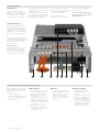
Übersicht
Übersicht
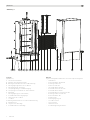
Abbildung 1
Legende
(alphabetisch):
A Anschlussset Schutzleiter
B Gehäuse / Befestigung Schutzleiter
C Öffnungen im Gehäuse für seitliche Kabelzuführung
D Befestigungsmöglichkeiten des Lochblechs
E Befestigung zweiter Schutzleiter
F Aussparungen/Stege zur Kabelbefestigung
G Aussparungen zur Aufnahme der Universalmodule
H Gerätefüße
I Befestigungsstege (für weitere Geräte)
J Schraubensatz für Befestigungsstege
K Kantenschutz für Lochblech
L Lochblech
M Öffnung im Gehäusedeckel für seitliche Kabelzuführung
N Gehäusedeckel
O Langloch für Frontmontage
P Schraubensatz für Frontmontage
Zubehör
Folgende Montagehilfen/Zubehörteile werden im Polybeutel mitgeliefert:
- 10x Gerätefuß
- 2x Sechskantmutter M6 DIN 934
- 2x Unterlegscheibe A6.4
- 2x Fächerscheibe A6.4
- 1x Schraube M6x25 DIN 933
- 4x Schraube ST2.9x9.5 DIN 7981
- 4x Schraube M4x25 DIN 84
- 2x Schraube M4x12 Linsenkopf DIN 7985
- 6x Unterlegscheibe A4.3 DIN 9021
- 6x Sechskantmutter M4
- 4x Kantenschutz
- 2x Befestigungssteg 270
- 1x Lochblech PP-AP
- 1x Deckel PP-AP
- 1x Gehäuse PP-AP
- 2x Verbindungsleitung Schutzleiter
NI J L OA MKB D D HC F GA PE

Allgemeines 3
Allgemeines
Bestimmungsgemäßer
Gebrauch
Das Multimedia-Patchpanel –
im folgenden „MM Ap“ – ist als
Wandverteiler für die Installation
Allgemeines
Montageort/Vorbereitung zur Wandbefestigung
Der Montageort des MM Ap sollte
so gewählt werden, dass folgende
Kriterien erfüllen sind:
· keine direkte Sonnenstrahlung
· ebener/tragfähiger Montage-
untergrund (das Leergewicht
des MM Ap beträgt 6,8 kg)
Wandbefestigung
1 Nutzen Sie die auf der „Bohr-
schablone“ (siehe Abb. 8)
genannten Ab stände, um die
Bohrlöcher zur Befestigung
des Gehäuses (C) vorzube-
reiten.
Beachten Sie bei der Wahl
und der Platzierung der
Dübel, dass das MM Ap in voll
bestücktem Zustand z.B. über
10 kg wiegen kann.
2 Kontrollieren Sie vor der
endgültigen Montage, ob die
anzuschließenden Kabel die
benötigten Längen haben.
Erdung
3 Zur Vorbereitung der Erdung
des Patchpanels befestigen
Sie die mit normgerechter Ver-
schraubung im Lieferumfang
enthaltenen Schutzleiter (A)
am Gehäuse.
Gehäusemontage
4 Drücken Sie von hinten die
mitgelieferten Füße (H) im
Gehäuse ein.
5 Befestigen Sie das Gehäu-
se – ggf. mit vorher erfolgter
Montage der Zubehörteile und
Geräte (siehe Seite 4 ff.) – an
der vorbereiteten Stelle und
verbinden Sie den Schutzleiter
mit einer geeignetern „Erdung-
quelle“.
von zentralen Rundfunk-, Kommu-
nikations- und Informationsgeräten
(RuK / IuK) gedacht.
Die verschiedenen Befestigungs-
ebenen und das mitgelieferte
Zubehör erlauben eine einfache
und platzsparende Montage von
Multimedia-Komponenten wie z. B.
Satelliten-Multischalter, Switch,
Router etc. sowie eine übersicht-
liche und sichere Verlegung und
Befestigung diverser Kabeltypen.
Das Gehäuse bietet die Möglich-
keit maximal fünfzehn Module im
Keystoneformat aufzunehmen.
Benutzen Sie das Panel zu
keinem anderen Zweck. Setzen
Sie es nur in Innenräumen ein.
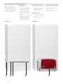
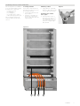
Beispiel (Abbildung 2)
Das Beispiel rechts zeigt (in Unter-
sicht) die Bestückung des MM Ap
mit einem Satelliten-Multischalter
(V), Switch (T) und Verkabelung für
je vier unterschiedliche Anschluss-
Universalmodule (S).
Die Positionierung des Gehäuses
kann so gewählt werden, dass
der untere Teil des Gehäuses sich
direkt über einer 230 V Steckdose
(U) und dem Kabelauslass (R) in
einer Wand befindet.
Empfehlung
Ein zusätzlich erforderlicher Router
kann später auf den Gehäuse-
deckel montiert werden und ist
somit im alltäglichen Gebrauch
besser kontrollier- und bedienbar
(siehe Abbildung 7).
S S ST VRQ QU

4 Montage
Montage
Platzierung der Zubehörteile und Module
Für die sichere und platzsparende
Befestigung der Komponenten
stehen Ihnen zur Verfügung:
· 15 Keystone-Modulauf-
nahmen (G)
· 2 Befestigungsstege (I)
· 1 Lochblech (L) mit Rundum-
Kantenschutz (K)
Nachbestellbar sind Befestigungs-
steg und Lochblech.
Module einsetzen
Die Platzierung der Module in die
fünfzehn vorgesehenen Ausspa-
rungen im Gehäuse ist frei.
6 Führen Sie ein konfektionier-
tes Modul (S) von „oben“ zu.
7 Haken Sie das Modul mit der
Rastnase auf dem Blech ein
und rasten es nach unten ein.
Kabel befestigen
8 Befestigen Sie die Kabel
einzeln mit Kabelbindern
zwischen den Aussparungen
(G) des Gehäuses.
Modul wieder lösen
9 Stecken Sie den Schrauben-
dreher von unten mittig vom
Modul hinter die Einschub-
blende (rechts, weißer Kreis)
und drücken Sie die Rast nase
schräg nach oben.
Abbildung 4
Abbildung 3
FSGI

Montage 5
Montage
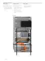
Platzierung der Zubehörteile
Befestigungsstege
Die Befestigungsstege können
je nach Bedarf waagerecht oder
senkrecht eingesetzt werden.
10 Montieren Sie die Befesti-
gungsstege in der gewünsch-
ten Ausrichtung und im
erforderlichen Abstand mit
den zugehörigen Schrauben
und Unterlegscheiben.
Lochblech
Auf dem mitgelieferten Lochblech
(L) können je nach Bedarf zusätz-
liche Geräte befestigt werden.
11 Montieren Sie das Lochblech
auf der zweiten Ebene (D)
„oben“ oder „unten“ mit dem
zugehörigen Schraubenset.
12 Setzen Sie danach den mit-
gelieferten Kantenschutz (K)
auf alle vier Kanten des Loch-
blechs, um eine Beschädi-
gung der Kabel zu vermeiden.
Kabelführung
13 Verlegen und fixieren Sie die
Kabel und Stromleitungen
(W) so, dass diese beim Auf-
setzen des Gehäusedeckels
nicht gequetscht werden.
Abbildung 5
D W

6 Montage
Montage
Gehäusedeckel aufsetzen/Platzierung eines Routers
Nach erfolgter Montage der
Module, Komponenten und
Kabel sowie der Erdung und
Befestigung des Gehäuses (siehe
Seite 3 unten) kann – nach ggf.
gewünschter Frontmontage z.B.
eines Routers – der Gehäuse-
deckel aufgesetzt werden.
Frontmontage
14 Setzen Sie die Schrauben
im noch nicht aufgesetzten
Zustand im Langloch (O) des
Gehäuse deckels (N) ein.
Verwenden Sie die Unterleg-
scheiben aus Kunststoff (P),
um einer Beschädigung der
Gehäuseoberfläche vorzu-
beugen.
15 Messen Sie den erforderlichen
Abstand der Schraubenköpfe
(X) analog zum Abstand der
Befestigungslöchern Ihres
Routers aus und ziehen Sie
die Schrauben handfest an.
Gehäusedeckel aufsetzen
16 Setzen Sie den Gehäuse-
deckel von oben auf das
Gehäuse auf. Mit leichtem
Druck unten rastet der
Ge häusedeckel ein.
Router aufsetzen
17 Stecken Sie den Router
vorsichtig auf die Schrauben-
köpfe auf.
18 Schließen Sie den Router an.
Gehäusedeckel abnehmen
Lösen Sie evtl. vorhandene Verka-
belungen eines evtl. auf der Front-
seite montierten Gerätes.
Hebeln Sie den Gehäusedeckel
nach oben ab.
Abbildung 6 Abbildung 7
XO YXN

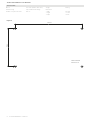
Technische Daten/Bohrschablone 7
Technische Daten/Bohrschablone
Technische Daten
Farbe reinweiß (ähnlich RAL 9010)
Schirmgehäuse vollgeschirmte Metallausführung
Anzahl Keystone-Module max. 15
Gewicht 6800 g
Abmessungen
- Breite 302 mm
- Höhe 151 mm
- Tiefe 70 mm
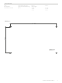
Abbildung 8
Abstände Bohrlöcher
Artikel 239 101 18
270 mm
453,7 mm

8 Entsorgung
Entsorgung
Bitte leisten Sie Ihren Beitrag zur
Entlastung der Umwelt, indem
Sie dieses Gerät nach Ende
seiner Nutzung einer umweltge-
rechten Verwertung zuführen.
Auf keinen Fall sollten Sie das
Gerät in den unsortierten Sied-
lungsmüll geben.
Entsorgung

Overview 9
Overview
Overview
Figure 1
Legend
(alphabetical):
A Connection set for grounding connector
B Housing/grounding connector mounting
C Openings in the housing for lateral cable supply
D Perforated sheet mounting options
E Mounting of second grounding connector
F Recesses/bars for cable mounting
G Recesses for the accommodation of the universal modules
H Device bases
I Mounting bars (for further devices)
J Screw set for mounting bars
K Edge protection for perforated sheet
L Perforated sheet
M Opening in the housing cover for lateral cable supply
N Housing cover
O Elongated hole for front assembly
P Screw set for front assembly
Accessories
The following assembly aids/accessories are also supplied in a poly bag:
- 10x device base
- 2x M6 DIN 934 hexagon nut
- 2x A6.4 washer
- 2x A6.4 serrated washer
- 1x M6x25 DIN 933 screw
- 4x ST2.9x9.5 DIN 7981 screw
- 4x M4x25 DIN 84 screw
- 2x M4x12 DIN 7985 round head screw
- 6x A4.3 DIN 9021 washer
- 6x M4 hexagon nut
- 4x edge protection
- 2x 270 mounting bar
- 1x PP-AP perforated sheet
- 1x PP-AP cover
- 1x PP-AP housing
- 2x connecting cable for grounding connector
NI J L OA MKB D D HC F GA PE

10 General information
General information
Intended use
The multimedia patch panel, here-
inafter referred to as “MM Ap”, is
intended for use as a wall-mount-
ed distributor for the installation
of central radio, communication
General information
Assembly location / preparation for wall mounting
The assembly location of the MM
Ap should be selected in such a
manner that the following criteria
are met:
· No direct sunlight
· Level/stable assembly sub-sur-
face (the empty weight of the
MM Ap is 6.8 kg)
Wall mounting
1 Use the distances as stated
on the “drilling template” (see
Figure 8) in order to prepare
the drill holes to mount the
housing (C).
When selecting and position-
ing the dowels, please note
that the MM Ap in a fully-load-
ed state can weigh over 10 kg
for instance.
2 Prior to performing the final
assembly, check whether the
cables that are to be connect-
ed are long enough.
Earthing
3 In order to prepare the earth-
ing of the patch panel, mount
the grounding connector
(A) included in the scope of
delivery on to the housing
using a standardised screw
connection.
Housing assembly
4 From behind, push the
supplied bases (H) into the
housing.
5 Mount the housing – follow-
ing the prior assembly of the
accessories and devices
where necessary (see Page
4 et seq.) – at the prepared
location and connect the
grounding connector with a
suitable “earthing source”.
and information devices (radio and
communication/information and
communication).
The various mounting levels and
the supplied accessories permit a
simple and space-saving assem-
bly of multimedia components
such as satellite multi-switches,
switches, routers, etc. as well as a
clear and safe laying and mount-
ing of various cable types.
The housing provides the
opportunity to accommodate a
maximum of fifteen modules in
keystone format.
Do not use the panel for any
other purposes. It may only be
operated indoors.
Example (Figure 2)
The example on the right illus-
trates (from below) how the MM
Ap is equipped with a satellite
multi-switch (V), a switch (T) and
cabling for four respectively differ-
ent connection universal modules
(S).
The housing can be positioned in
such a manner that the lower part
of the housing is directly above a
230 V socket (U) and the cable
outlet (R) in a wall.
Recommendation
An additionally-required router can
be mounted on to the housing
cover at a later date and, as a
result, it is easier to manage and
operate in daily use (see Figure 7).
S S ST VRQ QU

Installation 11
Installation
Positioning of the accessories and modules
The following items are available to
you for the safe and space-saving
mounting of the components:
· 15 keystone module
recordings (G)
· 2 mounting bars (I)
· 1 perforated sheet (L) with cir-
cumferential edge protection (K)
The mounting bar and perforat-
ed sheet can be retrospectively
ordered.
Inserting modules
The modules can be positioned
in the fifteen provided recesses in
the housing as desired.
6 Insert an assembled module
(S) from above.
7 Using the locking tab, hook
the module on to the sheet
and lock it into place by push-
ing downwards.
Mounting cables
8 Using cable ties, individually
fasten the cables between the
recesses (G) of the housing.
Removing the module
once again
9 From the bottom centre of
the module, insert the screw-
driver behind the slide-in
cover (right, white circle) and
push the locking tab diago-
nally upwards.
Figure 4
Figure 3
FSGI

12 Installation
Installation
Positioning the accessories
Mounting bars
The mounting bars can be
inserted horizontally or vertically
depending on the requirements.
10 Assemble the mounting bars
in the desired alignment and
at the required distance using
the associated screws and
washers.
Perforated sheet
Additional devices can be mount-
ed on to the supplied perforated
sheet (L) as required.
11 Mount the perforated sheet on
the „top“ or „bottom“ second
level (D) using the associated
screw set.
12 Then apply the supplied
edge protection (K) on all
four edges of the perforated
sheet in order to prevent cable
damage.
Cable guidance
13 Lay and fix the cables and
power lines (W) in such a
manner that they are not
crushed when applying the
housing cover.
Figure 5
D W

Installation 13
Installation
Applying the housing cover/positioning a router
Following the successful assembly
of the modules, components and
cables as well as the earthing and
mounting of the housing (see bot-
tom of Page 3), the housing cover
can now be applied, following
the front assembly of a router for
instance if desired.
Front assembly
14 Insert the screws in an as-yet
loaded condition into the elon-
gated hole (O) belonging to
the housing cover (N).
Use plastic washers (P) in
order to present damage to
the housing surface.
15 Measure the required dis-
tance of the screw heads (X)
analogous to the distance of
the mounting holes of your
router and tighten the screws
by hand.
Applying the housing cover
16 From above, apply the hous-
ing cover on to the housing.
The housing cover locks into
place when a slight amount of
pressure is applied.
Applying the router
17 Carefully place the router on
to the screw heads.
18 Connect the router.
Removing the housing
cover
Undo potentially present cables
belonging to a device that may be
assembled on the front side.
Lift up the housing cover.
Figure 6 Figure 7
XO YXN

14 Technical data/Distance of drill holes
Technical data/Distance of drill holes
Technical data
Colour Pure white (similar to RAL 9010)
Shield housing Fully-shielded metal design
Number of keystone modules max. 15
Weight 6800 g
Dimensions
- Width 302 mm
- Height 151 mm
- Depth 70 mm
Figure 8
Distance of drill holes
Article 239 101 18
270 mm
453.7 mm

Disposal 15
Disposal
Disposal
Please take part in protecting our
environment by properly recycling
this device at end of lifetime.
You should never dispose this
device in the regular garbage.
Improper disposal of electro nic
waste can release dangerous
substances into the environment
and affect public health.

© Wilhelm Rutenbeck GmbH & Co. KG · 293 768 · Rut032· Stand/Status 06.20
Technische Änderungen vorbehalten/Subjected to technical changes
Klagebach 33
D-58579 Schalksmühle
Telefon (0 23 55) 82-0
Telefax (0 23 55) 82-105
www.rutenbeck.de
-
 1
1
-
 2
2
-
 3
3
-
 4
4
-
 5
5
-
 6
6
-
 7
7
-
 8
8
-
 9
9
-
 10
10
-
 11
11
-
 12
12
-
 13
13
-
 14
14
-
 15
15
-
 16
16


Rutenbeck 23910118 - MM Ap Benutzerhandbuch
- Typ
- Benutzerhandbuch
in anderen Sprachen
Verwandte Artikel
Andere Dokumente
-
Bodensteckdosen Systemtechnik 5602E Benutzerhandbuch
-
Garant workbench assemblies Bedienungsanleitung
-
Triotronik PKW-TOUGH-K6 20.0 GE Datenblatt
-
Triotronik PKT-SLIM-KAT6 20.0 OR Benutzerhandbuch
-
CAB Apollo Benutzerhandbuch
-
-
Alpenföhn Matterhorn rev.B Installationsanleitung
-
Triton PKT-STP-SLIM-KAT6 15 SW Benutzerhandbuch
-
Bartscher A114001 Bedienungsanleitung